Table of Contents
Advertisement
Advertisement
Table of Contents

Related Manuals for ZKaccess F18

Summary of Contents for ZKaccess F18
- Page 1 www.zkaccess.com...
-
Page 2: Table Of Contents
Safety Precautions How to place a finger Product Contents Product PIN Diagram Product Dimensions Cables and Connectors Installation of Back Plate Power Connection Ethernet Connection PC RS485 Connection FR1200 RS485 Connection Lock Relay Connection Weigand Input Connection Weigand Output Connection Installation Reference Specifications Electrical Specifications... -
Page 3: Safety Precautions
Safety Precautions The following precautions are to keep user’s safe and prevent any damage. Please read carefully before installation. Do not place a magnet near the product. Magnetic Do not install the device in an area subject to Do not place the device next to field from magnets, CRT, TV, monitor or speaker direct sunlight, humidity or dust heating equipment. - Page 4 Safety Precautions The following precautions are to keep user’s safe and prevent any damage. Please read carefully before installation. Do not drop the device. Do not disassemble, repair or Do not use the device for any alter the device. other purpose than specified. In cleaning, do not splash water Do not damage the device on the device but wipe it out with...
-
Page 5: How To Place A Finger
H ow to Place a Finger ZkTeco’s fingerprint readers will give optimal results for fingerprint matching if the following recommendations and suggestions are followed. Select a finger to enroll It is recommended to use an index finger or a middle finger. ... - Page 6 H ow to Place a Finger Tips for different fingerprint conditions ZKTeco’s fingerprint products are designed to verify fingerprints with highest security irrespective of the conditions of the skin of the finger. However, in case a fingerprint is not read on the sensor, please refer to the followings tips.
- Page 7 H ow Does F18 work Register finger Identification Feature extraction Verified successfully Open door Thank you ! Verify feature Verification Door closed failed Please try again ! Fingerprint database Create Event logs Stored...
-
Page 8: Product Contents
Product Contents Basic Contents Screw Driver – 2 pcs. Wall Mounting Screws – 4 pcs. Wall Plugs– 4 pcs Star-shape Screw for Mini-USB Cable -1 pcs Mounting Plate -2 pcs 2 pin, 4 pin, 7 pin, 8 pin, Mounting Paper Metallic Back Plate 10 pin cables –... -
Page 9: Optional Accessories
Product Contents Optional accessories 12VDC, 3A Power Weigand Card Reader FR1200 Slave Fingerprint Reader K1-1 Exit Button Adaptor Prox Card USB Memory Alarm RS485 Convertor... -
Page 10: Product Pin Diagram
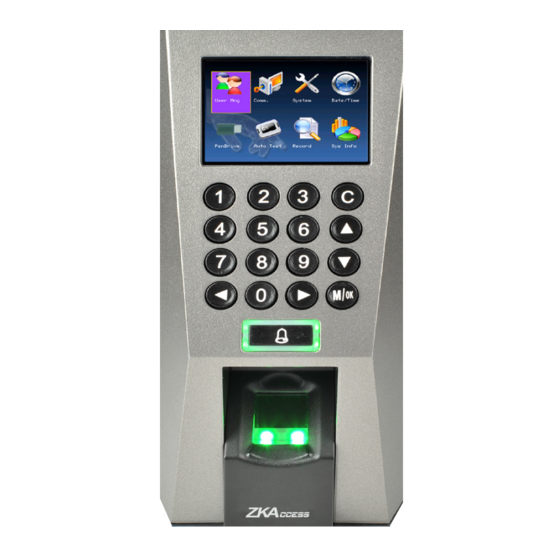
Product PIN Diagram Front Side 2.4 inch TFT LCD USB Memory slot Reset Switch Keypad & RF Card Area Door Bell & LED Indicator Speaker Slot ZK Optical Sensor... - Page 11 Product PIN Diagram Bottom Back 4 pin Cable connectors –Ethernet (TCP/IP) Beep, LED Weigand In 7 pin Cable connectors Power Out Weigand Out RS232 8 pin Cable connectors RS485 2 pin Cable connectors -Power In Bell Door Sensor 10 pin Cable connectors Button Lock...
-
Page 12: Product Dimensions
Product Dimension 80mm 80mm (3.15in.) (3.15in.) 183mm (7.20in.) 183mm 183mm (7.20in.) (7.20in.) 42mm (1.65in.) Front Side Back Plate... -
Page 13: Cables And Connectors
Cables and Connectors Digital input and Relay output Door Lock Alarm Button Sensor Door Bell Weigand output and RS485 Weigand RS232 RS485 Output Weigand input and Power out Weigand Power Out Beep Input Ethernet TCP/IP Power In Power In... -
Page 14: Installation Of Back Plate
Installation of Wall-mount Fix back plate to the wall Mount F18 terminal on the Secure F18 and back plate using wall mounting screws Back plate using a star shape screw. Star-shaped screw Wall mounting screws Star-shaped screw... -
Page 15: Power Connection
Power Connection Without UPS 12V DC (Red) 12V DC GND (Black) With UPS (Optional) 12V DC (Red) 12V DC GND (Black) Recommended power supply 12V ± 10%, at least 500mA. Comply with standard IEC/EN 60950-1. ... -
Page 16: Ethernet Connection
Ethernet Connection Ethernet Connection TCP/IP TCP/IP... - Page 17 Ethernet Connection Direct Connection to PC TCP/IP...
-
Page 18: Pc Rs485 Connection
PC RS485 Connection PC RS485 Connection RS232 RS485B RS485A Important Notes Do’s and Dont’s for RS485 connection 1. RS485 communication wires should be a shielded or twisted pair cable. RS485 communication wires should be connected in a bus cascade instead of a star form, to achieve a better shielding effect by reducing signal reflection during communications. -
Page 19: Fr1200 Rs485 Connection
1-4 is for RS485 address , switch 5 is reserved , switch 6 is for reducing noise on long RS485 cable. 3. If FR1200 is powered from F18 terminal ,the length of wire should be less than 100 meters or 330 ft. -
Page 20: Lock Relay Connection
Lock Relay Connection For Normally Open -Lock FR107 Sensor Sensor 12V DC 12V DC Lock... - Page 21 Lock Relay Connection For Normally Close-Lock Sensor Sensor 12V DC 12V DC FR107 Lock...
-
Page 22: Weigand Input Connection
Weigand Input Connection DC+(6-14V) +12V Weigabd1 INWD1 Weigand0 INWD0 RLED Green LED GLED Beeper Beep Weigand Card Reader... -
Page 23: Weigand Output Connection
Weigand Output Connection Access controller... -
Page 24: Installation Reference
Installation Reference Standalone LOCK Alarm Door Sensor Exit button Door... - Page 25 Installation Reference Third Party Controller Weigand Output Connection Weigand Weigand Output Weigand Output Weigand Output Output LOCK LOCK Outside Door Door Sensor Inside Door Inside Door Door Sensor Outside Door...
- Page 26 Installation Reference Third Party Controller RS485 Connection EXT RS485 EXT RS485 EXT RS485 EXT RS485 LOCK LOCK Outside Door Door Sensor Inside Door Inside Door Door Sensor Outside Door...
-
Page 27: Specifications
Specification Item Specification Fingerprint capacity 3,000 Transaction capacity 100,000 Hardware Platform ZEM720 ZK 6001, 400Mhz Memory 64M Flash, 32MSDRAM Fingerprint Sensor ZK optical sensor Display 2.8” TFT LCD color screen LED Indicator Red, Green Communication Ethernet(10/100M), RS485, USB-HOST, Weigand signal Wiegand Input and Wiegand Output Identification speed ≤2 sec... -
Page 28: Electrical Specifications
Electrical Specification Min. Typ. Max. Notes Working power supply Voltage(V) 14.4 Use regulated DC power adaptor only Current(A) Electronic lock relay output Switching voltage(V) Use regulated DC power adaptor only Switching Current(A) Switch Aux. input Pull-up resistance (Ω) 4.7k The input ports are pulled up with 4.7k resistors WEIGAND Input Voltage(V) 10.8... -
Page 29: Troubleshooting
Check whether the device and back plate are securely connected to each other. If not, a tamper switch is activated which triggers the alarm and keeps it ringing. How to set F18 used as fingerprint reader on Inbio access controller. Please contact our technical support department... - Page 30 Functions and specifications of the product are subject to change without notice due to quality enhancement or function update. For any inquiry for the product, please contact ZKACCESS.
Need help?
Do you have a question about the F18 and is the answer not in the manual?
Questions and answers