Subscribe to Our Youtube Channel
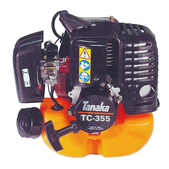
Summary of Contents for Tanaka TC-355
- Page 1 Service Manual TC-355 Date 05-19-02 UTILITY ENGINE ISM, Inc. • 1028 4 Street SW • Auburn, WA 98001 • Phone: (253) 333-1200 • Fax: (253) 333-1212 www.tanaka-usa.com custsvc@tanaka-ism.com...
-
Page 2: Table Of Contents
Service Manual TC-355 Table of Contents Specification Chart & Torque Limits ………..……………………….2 Trouble Shooting ………………………………...3 Safety and Shop Practices ………………………………...4 Routine Maintenance ………………………………...4 Diagnostic Tools ………………………………...5 General Inspection ………………………………6-8 Engine Repair ……………….……………9-17 Warranty Statement ………………….……………18 www.tanaka-usa.com custsvc@tanaka-ism.com... -
Page 3: Trouble Shooting
Service Manual TC-355 Trouble Shooting Engine Will Not Start Check Function of: Page No. Rewind Starter ………………6, 10, 11 Ignition System: No Spark …………...7, 8, 11, 12 Fuel System : Fuel Tank ………….…….6, 8, 13 Fuel System : Carburetor …………..8, 13, 14,15 Air Filter ……………………….6... -
Page 4: Safety And Shop Practices
Tools, instruments, and parts needed for work should be clean and readily available before any job is started. (Special tools available for servicing TANAKA equipment are listed in this manual.) Equipment should be cleaned before repair work starts. Cleaning will often help reveal a source of trouble. -
Page 5: Diagnostic Tools
Service Manual TC-355 Diagnostic Tools Compression Gauge Pressure Tester Part No. 27286 Part No. 070-2000W-500 Engine Tachometer (Digital Type) Three Point Spark Tester Ohmmeter (Digital Type) Part No. 001-29000-000 Disassembly & Assembly Tools Flywheel Remover Set 1. Handle (006-29326-002) Pin Remover 2. -
Page 6: General Inspection
Service Manual TC-355 General Inspection Once the engine is removed from the equipment, this is an ideal time to inspect for damage as well as potential areas that may require repair. Some of the diagnostic evaluation cannot be effectively performed after disassembly has begun. -
Page 7: Choke Lever
Service Manual TC-355 General Inspection Cont. Choke Lever Check to ensure that the choke lever (A) is able to rotate freely within the air cleaner body, and that it has not been bent as to prevent a good seal when closing over the air intake. - Page 8 Service Manual TC-355 General Inspection Cont. Spark Testing While the rubber spark plug boot / high-tension lead are removed from the spark plug, this is an ideal time to test the quality of the current being delivered to the spark plug. Insert a three point spark tester into the spark plug boot and briskly pull the recoil starter.
-
Page 9: Engine Repair
Service Manual TC-355 Engine Repair ENGINE SERVICE Troubleshooting should alert you to problem areas, and these problem areas can be addressed as major sub-components of the engine: • Centrifugal Clutch • Recoil Starter • Electrical System • Fuel System Components •... - Page 10 Service Manual TC-355 Engine Repair Cont. RECOIL STARTER CAUTION: The recoil spring is wound with significant force. When removed from the starter body, it will rapidly unwind. It is recommended that you wear gloves and eye protection when removing the starter spring.
- Page 11 Service Manual TC-355 Engine Repair Cont. Recoil Starter cont. It is necessary to increase the spring tension in the starter prior to use. Rotate the spool counterclockwise several times with the rope hooked into notch (A). Hold the spool to prevent it from rewinding and pull the starter grip out to take up the rope slack.
- Page 12 Service Manual TC-355 Engine Repair Cont. Electrical Systems cont. With the flywheel nut removed, a flywheel puller can be attached to separate it from its’ press fit to the crankshaft. Align the center bolt of the puller with the indent in the end of the crankshaft, and thread at least two carrier bolts through the puller and into the flywheel.
- Page 13 Service Manual TC-355 Engine Repair Cont. FUEL SYSTEM The fuel system consists of the carburetor (1), fuel tank (2), fuel supply line (3), and fuel filter (4). The carburetor is held in place between the air cleaner body and the...
- Page 14 Service Manual TC-355 Engine Repair Cont. Fuel Systems cont. The pump body of the carburetor is held together with four screws. With these screws removed, it will be possible to inspect all of the pump components of the carburetor. Inspect all gaskets and diaphragms to ensure that they have not lost their pliability, and show no signs of cracking or drying.
- Page 15 Service Manual TC-355 CARBURETOR SERVICE The main body of the carburetor consists of the carburetor body (A), the throttle shaft (B) and the throttle wire receiver (C). Two screws secure the throttle wire receiver and the throttle shaft to the carburetor body. While it’s not...
- Page 16 Service Manual TC-355 Engine Repair Cont. CRANKCASE / ENGINE When re-assembling the muffler components, be sure that the heat shield is properly installed with the muffler locator tabs properly inserted. The heat shield is crucial to the cooling of the engine, and improper installation can lead to overheating of the engine.
- Page 17 Service Manual TC-355 Engine Repair Cont. Crankcase / Engine cont. With the engine taken down to this level, it is generally accepted that the piston rings should be replaced. They provide the engine with the proper amount of compression, and due to their inaccessibility, it’s best to re-assemble with new rings.


Need help?
Do you have a question about the TC-355 and is the answer not in the manual?
Questions and answers