Table of Contents
Advertisement
Quick Links
Installation and Operational Guide
This instruction manual serves as a guide for the Avatar Exterior Light bar. IMPORTANT! Please read
through all provided instructions and any listed warnings in regards to product use.
Record Product Serial Number:
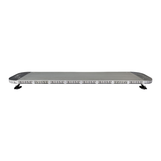
FENIEX AVATAR SERIES
MODEL # L-22109, L-23709, L-24809, L-25709
www.Feniex.com
E-mail: Support@feniex.com
Support line: 1.800.615.8350
Advertisement
Table of Contents

Subscribe to Our Youtube Channel
Related Manuals for Feniex L-22109


Summary of Contents for Feniex L-22109
- Page 1 Installation and Operational Guide FENIEX AVATAR SERIES MODEL # L-22109, L-23709, L-24809, L-25709 This instruction manual serves as a guide for the Avatar Exterior Light bar. IMPORTANT! Please read through all provided instructions and any listed warnings in regards to product use.
-
Page 2: Safety Regulations
24 months, while coverage for strobes, switches and flashers are for a 12 month term. If a manufacturer defect occurs within this time period, Feniex will repair or replace malfunctioning parts free of charge. -
Page 3: Warranty Limitations
WARRANTY LIMITATIONS This warranty shall not apply if this product is a.) used with products not sold or licensed by Feniex Industries, Inc. (including, but not limited to, power supplies, radios, control devices, adapters and power converters); b.) is used for rental;... -
Page 4: Wire Color
Alley Flashing Mode: Pattern displayed from Mode 1 selection Overrides: • Mode 2 will override Mode 1. Mode 3 will override Modes 1 and 2 • Takedown and Alley steady will always override Takedown and Alley flashing functions WIRING DIAGRAM www.Feniex.com ©Feniex Industries, Inc. - Page 5 Internal Controller Board Controller board is programmed to customer requirements. If the end user requires serviceability, please contact Feniex for assistance. Reverse Polarity Protection The light bar controller has built in reverse polarity circuit. This will protect the controller in the event the user reverse connects the 12V+ and 12V- inputs.
- Page 6 Avatar 27” will implement only positions 1, 2 and 6. The 37” will implement positions 1, 2, 3 and 6, while the 47” will use have positions 1,2,3,4, and 6. Required Wires: Position 1 – Black Position 2 – Red Position 3 – Orange Position 4 – Green Position 5 – Blue Position 6 – White WIRING DIAGRAM www.Feniex.com ©Feniex Industries, Inc.
- Page 7 Figure A M5 Phillips Screw Top Cover To service or replace a LED module: 1.) Remove the top cover by removing the metric M5 Phillips Screw on the center cover To gain access to the alley or corner modules the aluminum end cap must be removed. To gain access to the end cap, the center top cover must be first removed.
-
Page 8: Adjusting Height
Adjusting Height Depending on the height of the vehicle, the feet of the bar will need to be adjusted for the required height and angle of the vehicle. To adjust the height: 1.) Determine the location for the vehicle for the light bar and check that no equipment will be damaged when drilling holes in the vechile to mount the light bar. -
Page 9: Electrical Installation
100% of the maximum current and properly fused at the power source with the cor- rectly rated fuse. Avoid routing wires in the deployment area of the vehicle air bag or any other potentially hazardous locations. WIRING DIAGRAM www.Feniex.com ©Feniex Industries, Inc. - Page 10 Avatar Flash Pattern List The examples provided illustrate the series of patterns found in the Avatar exterior light bar series. Each group shown has 6 different modes of the pattern depicted. Group A: Half-half Pattern Group B: 1-1-1-1-1 Pattern • Single 50-50 •...
Need help?
Do you have a question about the L-22109 and is the answer not in the manual?
Questions and answers