Table of Contents
Advertisement
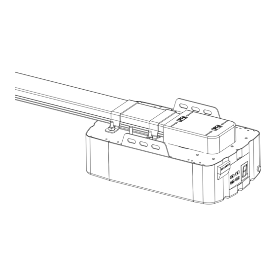
Sectional And Tilting Door Opener
Installation Instructions and User Guide
FS 600
FS 1000
FS 1200
S/N
Please read the manual carefully before installation and use.
The installation of your new door opener must be carried out by a technically qualified
or licensed person.
Attempting to install or repair the door opener without suitable technical qualification
may result in severe personal injury, death and / or property damage.
600N
1000N
1200N
WARNING
FS 600-Speed
FS 1000-Speed
600N
1000N
Advertisement
Table of Contents

Related Manuals for ForceDoor FS 600

Summary of Contents for ForceDoor FS 600
- Page 1 Sectional And Tilting Door Opener Installation Instructions and User Guide FS 600 600N FS 600-Speed 600N FS 1000 1000N FS 1000-Speed 1000N FS 1200 1200N WARNING Please read the manual carefully before installation and use. The installation of your new door opener must be carried out by a technically qualified or licensed person.
-
Page 2: Table Of Contents
CONTENTS Important Safety Recommendations...…………………………….……………………………..1 Product Description & Features....................2 Pre-Installation Recommendations ..................3 Installation (Wall Bracket & Door Bracket) ................3 Installation (Steel Track)………………………………………….…………………………….…..4 Installation (Sectional Steel Track Assembly).................5 Installation (Aluminium Track)....................6-7 Battery backup Assembly (optional)..............7 Programming Instructions....................8-9 Terminal Introduction and Application.................10-11 Manual Disengagement......................12 Maintenance……………………………………………………………………………………….12 Technical specifications………………………………………………………………………..13-14 Parts Listing…………………………………................15... -
Page 3: Important Safety Recommendations
IMPORTANT SAFETY RECOMMENDATIONS FAILURE TO COMPLY WITH THE FOLLOWING SAFETY RECOMMENDATIONS MAY RESULT IN SERIOUS PERSONAL INJURY, DEATH AND / OR PROPERTY DAMAGE. 1. PLEASE READ CAREFULLY AND ADHERE TO ALL SAFETY AND INSTALLATION RECOMMENDATIONS. 2. The opener is designed and manufactured to meet local regulations. The installer must be familiar with local regulations required in respect of the installation of the opener. -
Page 4: Product Description & Features
PRODUCT DESCRIPTION & FEATURES 1. Automatic safety reverse Automatic stop / automatic reverse are controlled by our software of circuit boards. We are circumspect to protect your children, pet or other goods. 2. Soft start / Soft stop Ramping speed up and down at the start and end of each cycle reduces stress on the door and opener for longer life, and makes for quieter operations. -
Page 5: Pre-Installation Recommendations
PRE-INSTALLATION RECOMMENDATIONS 1. Garage door must be able to be lifted and closed easily by hand and without much effort. A well balanced & sprung door is critical for proper installation. 2. The garage door opener can’t compensate for a badly installed garage door and should not be used as a solution for a “hard to open”... -
Page 6: Installation (Steel Track)
Installation (Steel Track) Figure 3 STEP1 (Fig.3) Attach the opener head to the steel track. Assembly the 2 “U” Hanging brack ets with 6mm nuts supplied. STEP2 (Fig.3) Place the steel track and opener head assembly centrally on the garage floor, with the open head furthest away from the door. -
Page 7: Installation (Sectional Steel Track Assembly)
Sectional Steel Track Assembly 2 Parts Steel Track A:1500 mm B:1500 mm Sleeve 3 Parts Steel Track D:1000 mm C:1000 mm E:1000 mm Sleeve Sleeve 1. 2-Parts Track: As Fig.6, slide the A rail into the sleeve, slide the B rail into the sleeve. 3-Parts Track: As Fig.7, slide the C rail into the sleeve, slide the D rail into the sleeve;... -
Page 8: Installation (Aluminium Track)
Installation (Aluminium Track) Figure 11 STEP1(Fig.12, Fig.13) Insert the shuttle into the cut -out at the end of the Aluminium track. Be sure it faces the right direction (the disconn ection arm on the shuttle faces towards the opener head). Slide the shuttle along the rail until it locks into... -
Page 9: Battery Backup Assembly (Optional)
STEP5 (Fig.11) Lift and support the opener head (with a ladder) so it is positioned centrally and level. Fix the opener and track on ceiling by Iron bracket A & B. WARNING: Do not allow children around the do or, opener or supporting ladder Serious injury and/or damage may result fr om failure to follow this warning. -
Page 10: Programming Instructions
PROGRAMMING INSTRUCTIONS 1. PROGRAMMING OPEN & CLOSE LIMITS a) Press and hold SET Button until 1 appears on the display then release the button. The door opener is now in Programming Mode. b) Press and hold the UP until the door reaches the desired open position. - Page 11 4. OBSTRUCTION FORCE ADJUSTMENT CAUTION: the obstruction force adjustment is set automatically during programming. Normally no adjustment is necessary. a) Press and hold the SET button until 3 appears on the Increase Force display then release the button. The unit is now in force adjustment mode. b) Press the UP button to increase the force setting or the DOWN button to decrease the force setting.
-
Page 12: Terminal Introduction And Application
Photo beam connection (optional) – Fig.17,Fig.18 Switch control connection (optional) – Fig.17 Figure 17 Figure 18 Other terminal introduction and application 1.The O/S/C interfaces available. (Fig. 19, Fig. 20) Add a new O/S/C button to open or close the door. 2. - Page 13 Figure 19 Figure 20...
-
Page 14: Manual Disengagement
Manual disengagement The opener is equipped with a manual release cord to disengage shuttle and move door by hand while holding the handle down (Fig 21). Pull on the handle to disengage the shuttle. To re-engage the door simply run opener in automatic mode or move door by hand until the trolley engages in the chain shuttle. -
Page 15: Technical Specifications
Technical specifications FS 600 FS 1000 FS 1200 Input voltage 220 - 240V / 110 - 127V, 50–60 Hz Max. pull force 600 N 1000 N 1200 N ㎡ ㎡ ㎡ Max. door area 10.0 15.0 18.0 Max. door weight (Balanced) - Page 16 FS 600-Speed FS 1000-Speed Input voltage 220 - 240V / 110 - 127V, 50–60 Hz Max. pull force 600 N 1000 N Max. door area ㎡ ㎡ 10.0 15.0 Max. door weight (Balanced) 80 kg 100 kg Max. door height...
-
Page 17: Parts Listing
Parts Listing Item Description Item Description Item Description Control Panel Cover Switch Cover Straight Arm Opener Middle Cover C Rail - Steel Track Bracket - 2 LED light Cover U Hanging Bracket Trolley Assy - Bottom PCB(1) Track Bracket -1 Trolley Assy - Top PCB(2) Mounting Bracket... -
Page 18: Common Fault & Solutions
Common Fault & Solutions Fault appearance Fault cause Solutions No any working for openers Power supply Check the power supply from electronic plug on Plug wire are loosing openers. Carefully open the opener cover, check all plug wire on control boards. Faulty learning on “Up”...
Need help?
Do you have a question about the FS 600 and is the answer not in the manual?
Questions and answers