Audioaccess W.H.E.N. AVR21EN Installation Instructions Manual
The whole-house
entertainment network
Hide thumbs
Also See for W.H.E.N. AVR21EN:
- Brochure & specs (2 pages) ,
- Quick start manual (4 pages) ,
- Installation instructions manual (222 pages)
Table of Contents

Related Manuals for Audioaccess W.H.E.N. AVR21EN


Summary of Contents for Audioaccess W.H.E.N. AVR21EN
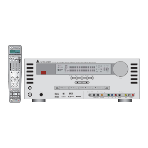
- Page 1 W.H.E.N. ™ The Whole-House Entertainment Network Installation Instructions Surr. Surr. Select Tuning AM/FM Preset Source Mode Mode Optimizer MIC In/out Game/Cam Optical 3 Coaxial 3 S-Video Video L-Audio-R...
-
Page 2: Table Of Contents
Table of Contents READ FIRST! Important Safety Precautions! HUB SYSTEM Main Room INTRODUCTION Hub Installation KEY FEATURES AVH21 CONFIGURATION Main Room AVH21 Hub Configuration Switch Remote Rooms HEAD END CONNECTIONS AVH21 Connections TYPOGRAPHICAL CONVENTIONS Power In IMPORTANT SAFETY INFORMATION Uplink/Multiroom Link Keypad Connections WHAT’S INCLUDED Source Video In... - Page 3 ADVANCED SETTINGS MAIN ROOM OPERATION Front-Panel Timeout Basic Operation Front-Panel Brightness Turning the AVR21EN On or Off Power-On Volume Main Room Sleep Mode On Screen Status Source Selection Main Menu Time-Out 6-Channel/8-Channel Direct Input Volume and Tone Control REMOTE CONTROL SETUP Video Processing Carrier Surround Mode Selection...
-
Page 4: Read First! Important Safety Precautions
READ FIRST! Important Safety Precautions! Read these instructions. Use only with the cart, stand, tripod, The lightning flash with arrowhead symbol, bracket or table specified by within an equilateral triangle, is intended Keep these instructions. the manufacturer or sold to alert the user to the presence of uninsu- Heed all warnings. -
Page 5: Introduction
Introduction AVH21 A/V distribution hubs provide a scalable option for Thank you for purchasing the Audioaccess ® W.H.E.N. ™ Whole-House Entertainment Network. This system utilizes distributing whole-house A/V and control signals. Digital the vast technological resources of the Harman International... -
Page 6: Key Features
Key Features Main Room KP21 keypads feature built-in 50W-per-channel stereo digital audio amplifiers for maximum efficiency and performance 70 Watts x 7-channel surround mode Keypad/zone local source line-level audio input for adding a Dual AM/FM tuners zone-specific component such as a dedicated cable box, satellite Three dedicated RS-232 Sony ®... -
Page 7: Important Safety Information
Important Safety Information Verify Line Voltage Before Use Avoid moist or humid locations. Do not obstruct the ventilation slots on the top of the unit, or Your AVR21EN has been designed for use with 120-volt AC current. place objects directly over them. Connection to a line voltage other than that for which it is intended can create a safety and fire hazard, and may damage the unit. -
Page 8: What's Included
What’s Included Unpacking AVR21EN Carton Contents: 1 – AVR21EN processor/controller The carton and shipping materials used to protect your new receiver during shipment were specially designed to cushion it from shock 1 – AVR21ENR1 remote control and vibration. We suggest that you save the carton and packing 1 –... -
Page 9: System Planning
System Planning Main Room The Audioaccess W.H.E.N. system is made up of three main system components (the AVR21EN processor/controller, AVH21 The Main Room component in a W.H.E.N. system is the AVR21EN A/V hub and WPS21 power hub) and three user interfaces processor/controller. -
Page 10: Remote Rooms
IR receiver can be connected to the KP21 keypad. By mum capabilities of the Audioaccess W.H.E.N. mounting the IR receiver at the “focal point” of the room (i.e., the... -
Page 11: Remote Rooms
All other connections will be done after construction and installation are finished. See also AVR21EN Connections The W.H.E.N. system will be compatible with the Channel Vision additional information. doorbell stations. Pull the appropriate wire to the AVH21. Please contact Audioaccess Technical Support for more information. -
Page 12: Avr21En Front-Panel Features
AVR21EN Front-Panel Features Surr. Surr. Select Tuning AM/FM Preset Source Mode Mode Optimizer MIC In/out Game/Cam Optical 3 Coaxial 3 S-Video Video L-A udio-R 18 19 12 13 14 Figure 1. AVR21EN Front Panel 1. Main Power Switch 17. Digital Input/Coaxial 3 Input/Output Status Indicator 2. - Page 13 AVR21EN Front-Panel Features 0 Main Power Switch: 6 Mode Adjust Down: Press this switch to apply power to the Press to move down in menu options Tone T Speaker S Channel R AVR21EN. When the switch is pressed in, the unit is placed in a when used with the Digital Sel Q...
- Page 14 AVR21EN Front-Panel Features H Tuner Mode Selector: Q Digital Input Selector: Press this button to select Auto or Press this button to begin the process Manual tuning. When the button is pressed so that of selecting a digital source for use with the currently selected input. A U T O / S T E R E O Upper Display Line W appears in the...
-
Page 15: Avr21En Front-Panel Information Display Features
AVR21EN Front-Panel Information Display Features Figure 2. AVR21EN Front-Panel Information Display 32. Surround Mode Indicators 35. Speaker/Channel Input Indicators 33. Upper Display Line 36. Input Indicators 34. Lower Display Line V Surround Mode Indicators: Y Speaker/Channel Input Indicators: One of these indicators will light These indicators are to show the surround mode in use. -
Page 16: Avr21En Rear-Panel Features
AVR21EN Rear-Panel Features RADIO 2 DISC 1 DISC 2/SAT RADIO DISC 3/MP3 CABLE/SAT DISC 2/SAT RADIO DISC 3/MP3 KP A/V MONITOR DISC 2/SAT RADIO DISC 3/MP3 DISC2/SAT RADIO DISC 3/MP3 RADIO 1 DISC2/SAT RADIO DISC 3/MP3 DISC 2/ DISC 3/ DISC 1 SAT RADIO 12 13 14 15... - Page 17 AVR21EN Rear-Panel Features 0 Disc 1 Analog Audio/Video Inputs: 22. Side Surround (7.1-Channel) or Connect the left/right Surround (5.1-Channel) Speaker Outputs analog audio and composite or S-video jacks of a DVD/CD player or other video source to these jacks. When digital audio and/or 23.
- Page 18 AVR21EN Rear-Panel Features 7 AUX Analog Audio/Video Outputs: H HDMI Output: Connect the left/right Connect this jack to the HDMI input on a analog audio and composite or S-video RECORD IN jacks of a video projector or monitor. HDMI connections should be restricted to recording device such as a DVD recorder, personal video recorder a maximum cable length of about 50 feet.
- Page 19 T Multiroom Link: These two RJ45 jacks may be used to add Control Out of an Audioaccess SPF-1 or other sensing device to pro- up to 20 additional rooms of audio/video signal distribution and vide source power ON/OFF status to the AVR21EN. These inputs system control when connected to Audioaccess W.H.E.N.
-
Page 20: Avh21 Front-Panel Features
AVH21 Front/Rear-Panel Features Figure 4. AVH21 Front Panel 10 11 12 13 14 15 Figure 5. AVH21 Rear Panel 1. Source Video Bypass Outputs 9. Power In 2. Keypad/Zone Video Outputs 10. Door 1 12/24V DC Latching Trigger Output 3. Camera Video Bypass Outputs 11. - Page 21 AVH21 Front/Rear-Panel Features One two-posi- Door 1 Dry-Contact Latching Trigger Output: Six female F-type terminals Source Video Bypass Outputs: tion plug-in terminal connects to a remote door lock that requires output the composite video signals connected to the AVH21 a latching dry-contact closure to activate. (This type of door lock Source Video Inputs for distribution of the six common- system would provide its own power to activate when the circuit is...
-
Page 22: Avh21 Status-Panel Features
AVH21 Top/Status-Panel Features Figure 6. AVH21 Top Panel Figure 7. AVH21 Status Panel 17. AVH21 Status Panel 23. Expansion Hub Connection Indicator 18. Hub Configuration Switch 24. Uplink Activity Indicator 19. Mounting Screw Holes 25. Keypad Connection Indicators 20. Reset Button 26. - Page 23 AVH21 Top/Status-Panel Features AVH21 Mounting Flange: See the AVH21 Front/Rear-Panel Expansion Hub Connection Indicator: One green LED Features section previous to this. lights up to indicate proper connection to the W.H.E.N. multiroom One adhesive lexan label fits into the AVH21 Status Panel: link network when the AVH21 Expansion/AUX KP Terminal recess on the AVH21 top panel to indicate power, hub connection,...
-
Page 24: Wps21 Front-Panel Features
WPS21 Front-Panel Features Figure 8. WPS21 Front Panel 9. Power Indicator 1. KP21 Keypad Power Fuses 5. AVH21 A/V Hub Power Terminal 10. Keypad Power Status Indicators 2. AVH21 A/V Hub Fuse 6. AC Power Cord Jack 3. WPS21 Mounting Flange 7. -
Page 25: Wps21 Top-Panel Features
WPS21 Top/Status-Panel Features POWER KEYPADS AV HUB 1 AUDIO HUB 1 Figure 9. WPS21 Top Panel POWER KEYPADS AV HUB 1 AUDIO HUB 1 Figure 10. WPS21 Status-Panel Label... -
Page 26: Kp21 Front-Panel Features
KP21 Front-Panel Features < < MENU BACK Figure 11. KP21 Front Panel (Without Bezel) 1. Keypad Mounting Screw Holes 12. Back Button 2. Page/Monitor Microphone 13. LCD Information Display 3. Keypad/Zone/System Power On/Off Button 14. Volume Down Button 4. IR Sensor 15. - Page 27 KP21 Front-Panel Features Keypad Mounting Screw Holes: Four circular openings used Main Menu Button: One backlit button allows return to the to attach the keypad two a two-gang electrical box using the four Main Menu from any selected keypad menu page. included screws.
-
Page 28: Kp21 Rear-Panel Features
KP21 Rear-Panel Features Figure 12. KP21 Rear-Panel (With Bezel) 22. IR IN Terminal 28. Zone/Keypad Amplifier 23. AVH Hub Terminal 29. Local Source Right Channel Input 24. Speaker Terminal 30. Local Source Left Channel Input 25. Keypad Address DIP Switch (Side) 31. -
Page 29: Spf Features (Source Power Flag)
KP21 Rear-Panel Features Keypad Mounting Screw Holes Keypad Bezel Zone/Keypad Amplifier: The 50-watt-per-channel digital Snap Tabs. KP21 Front-Panel Features on pp. 26–27. amplifier provides clean, high-power audio of a selected source to connected zone speakers by reducing the distance from the IR IN Terminal: One three-position plug-in terminal connects amplifier to the speakers. - Page 30 One 2.1mm coaxial jack connects to an Power Input: composite video or coaxial digital audio is present on this input Audioaccess SPF/PS power supply. telling the AVR the source is On. The 12V is cut when the signal is Allows connection of a “power bus” so Power Pass-Through: removed, telling the AVR the source is Off.
- Page 31 SPF (Source Power Flag) Features SPF #3 COMPOSITE VIDEO OR COMPOSITE VIDEO OR COAXIAL DIGITAL AUDIO COAXIAL DIGITAL AUDIO FROM SOURCE OUT TO AVR SOURCE IN 2V TO AVR SOURCE FLAG IN 2.1MM JUMPER WIRE SPF #2 COMPOSITE VIDEO OR COMPOSITE VIDEO OR COAXIAL DIGITAL AUDIO COAXIAL DIGITAL AUDIO...
-
Page 32: Main Room Installation & Setup
Main Room Installation and Setup IR EMITTER DVD PLAYER LINE-LEVEL AUDIO SPS SOURCE POWER SENSOR LINE LEVEL OUT DIGITAL AUDIO OUT COMPONENT VIDEO OUT RS232 S VIDEO FROM DVD CHANGER FROM DVD CHANGER OPTICAL COAXIAL TO AVR21EN TO AVR21EN SPS/PS COMPONENT VIDEO POWER SUPPLY FROM DVD CHANGER... -
Page 33: Installing Avr21En And Source Components
AVR rear panel. Audio – Disc 1 4. If using one SPF, connect the power input to an Audioaccess 1. Connect the L&R line-level audio outputs of a DVD/CD player SPF/PS power supply. If using multiple SPFs, connect the Power Disc 1 L&R In 0... - Page 34 This will 4. If using one SPF, connect the Power Input to an Audioaccess provide power for the A/V Adapter, the aDock and the iPod. SPF/PS power supply. If using multiple SPFs, connect the...
- Page 35 MAIN MENU/REMOTE 4. If using one SPF, connect the Power Input to an Audioaccess CONTROL SETUP. SPF/PS power supply. If using multiple SPFs, connect the Power...
-
Page 36: Antennas
Monitor Component Video Outputs E 4. If using one SPF, connect the Power Input to an Audioaccess to the component video inputs of SPF/PS power supply. If using multiple SPFs, connect the Power your TV, projector or other display device. -
Page 37: Speaker Connections
AVR21EN Speaker Connections RIGHT FRONT FRONT LEFT CENTER CHANNEL POWERED SUBWOOFER – 14 AWG 2-CONDUCTOR STRANDED SUB/LFE SPEAKER WIRE LINE IN – – SHIELDED AUDIO CABLE SIDE SURROUND AVR21 REAR PANEL SIDE SURROUND LEFT RIGHT – – PREAMP SUB OUT 14 AWG 2-CONDUCTOR STRANDED 14 AWG... -
Page 38: Subwoofer
NOTE 1: 10 feet. We do not recommend that you use cables with an AWG 1. Attach an IR emitter (Audioaccess IREMIT1) to the faceplate of equivalent of 18 or higher (smaller gauge), due to the power loss the device to be controlled. -
Page 39: Multiroom Installation & Setup
Multiroom Installation and Setup Installing W.H.E.N. System Components Keypad DIP Switch Settings Address W.H.E.N. allows unprecedented flexibility in system design for (Zone Number) incorporating whole-house A/V distribution and control, and home theater. For the purpose of detailing the options, the Multizone sections will be broken down into three groups: Main Room, Three-Zone System and Hub System. - Page 40 Multiroom Installation and Setup DVD CHANGER IR EMITTER DVD PLAYER LINE-LEVEL AUDIO SPF (SOURCE POWER FLAG) LINE LEVEL OUT DIGITAL AUDIO OUT COMPONENT VIDEO OUT RS232 S VIDEO FROM DVD CHANGER FROM DVD CHANGER OPTICAL COAXIAL TO AVR21EN TO AVR21EN SPF/PS COMPONENT VIDEO POWER SUPPLY...
-
Page 41: Speakers
Three-Zone System Three-Zone System Main Room The AVR21EN and all common-source components and speakers should be installed, connected and set up as described in the Pre-Wire/Main Room, Main Room Installation and Setup sections. Remote Rooms Keypads In addition, a Cat. 5e should be pulled from the KP21 keypad location in each remote zone (up to two) to the AVR21EN for control, audio and data. - Page 42 Multiroom Installation and Setup ZONE SPEAKERS WPS21 KP21 P O WER K E Y P ADS AV HUB 1 AUDIO HUB 1 VIDEO DISPLAY 24V DC FROM WPS21 TO KEYPADS 24V DC FROM WPS21 ZONE SPEAKERS TO AVH21 KP21 SPEAKER-LEVEL AUDIO FROM KP21 TO ZONE SPEAKERS CONTROL, DIGITAL AUDIO, DATA...
-
Page 43: Hub Installation
Hub System Hub System 1. Shelf Mount. The hubs can lay flat on a shelf, when appropriate in a given installation. Though the hubs typically run cool, adequate space should always be provided for airflow. Never Main Room place any object on top of a hub when shelf mounted. Utilize The AVR21EN and all common-source components and speakers the space created by the mounting flange for running wires should be installed, connected and set up as described in the... -
Page 44: Avh21 Configuration
Multiroom Installation and Setup AVH21 Configuration AVH21 Hub Configuration Switch The settings of the Hub Configuration Switch correspond Whether using one AVH21 or three, the hubs need to be to the “keyed” openings in the three lexan status-panel labels configured for “Hub Number” and “Zone Group” identification. included with each AVH21. -
Page 45: Uplink/Multiroom Link
Hub System Uplink/Multiroom Link Keypad Connections 1. Using Cat. 5e cable, properly terminated with RJ45 connectors, 1. Using Cat. 5e cable properly terminated with RJ45 connectors, Multiroom Link Terminal T connect the on the AVR21EN to connect the cables to the appropriate KP21 keypad terminals, on the AVH21, as shown in on the AVH21. -
Page 46: Source Video In
Multiroom Installation and Setup Source Video In Camera Video In 1. Using RG6 quad shield coaxial cable terminated with male F con- 1. Using RG6 quad shield coaxial cable terminated with male F Video Source Out Terminals a nectors, connect each of the connectors, connect each zone video monitor or security camera the AVR21EN rear panel to the appropriate composite video output to the appropriate... -
Page 47: Zone (Kp) Video Out
Hub System Zone (KP) Video Out 2. In larger systems using multiple hubs, repeat Step 1 for all 1. Using RG6 quad shield coaxial cable terminated with male F Video Output connections to AVH21 #s 1, 2 and 3 for all connectors, connect the appropriate KP Video Output 1–6 zones configured for video. -
Page 48: Door 1
120V AC outlet after all system connections have been made 5. In larger systems using multiple AVH21s, the Door 1 terminals and confirmed. Use the supplied cord or contact Audioaccess for can be used to activate different door locks in different areas. -
Page 49: Aux In (Local Source In)
Zone Connections AUX In (Local Source In) 2. Insert the twisted ends into the appropriate slots on the R+/R– L+/L– AUX-In Terminals on the KP21 rear panel, as This connection allows the audio from a local source such as a shown in Figure 29, and tighten with a small-blade screwdriver. -
Page 50: Speakers
Multiroom Installation and Setup Speakers 1. Using 16AWG two-conductor stranded wire, strip approximately 1/4" and twist the ends until there are no loose strands that can KP21 cause shorts. 2. Insert the twisted ends into the appropriate slots on the R+/R–... -
Page 51: Keypad Address (Zone Number)
System Setup Main Room (Home Theater) Setup Keypad Address (Zone Number) Settings Before making any connections to a KP21 Keypad, it must be con- When all audio, video and system connections have been made, figured for its unique keypad address (zone number). This address there are a few configuration adjustments that must be made. -
Page 52: System Setup
System Setup You are now ready to power up the AVR21EN to begin these final adjustments. 1. Make certain that the AC power cord is firmly inserted into the AC Power Cord Jack W and plug the cord into an unswitched AC outlet. -
Page 53: Making Configuration Adjustments
This will place an easily configurations with the resultant changes to the bass management viewed list of the available options on the screen. system. Thanks to the use of exclusive Audioaccess circuitry and software, along with DCDi by Faroudja technology, you may also ®... -
Page 54: System Configuration
System Setup Clock Setup Sources When the Main Menu Appears, the first item to be set is the system The first step is to configure each input. Once an input is clock. The cursor will be next to the CLOCK SETUP line. Press configured, the selection of an input will automatically recall Set Button H and CLOCK SETUP (... -
Page 55: Source Audio Input
System Setup bers and symbols. Press the button either way, until the first letter or tuner, you may wish to set the mode to Stereo (“Surround Off”) of the desired name appears. If you wish to enter a blank space as as they are not typically used with multichannel program material, Navigation Button F ›... -
Page 56: Dts
System Setup vary with the type of program material being played and the When an analog or 2-channel PCM source is playing, the DTS Neo:6 number of speakers in your system configuration. modes are available, which creates a 3-, 5- or 6-channel presentation of the sound. -
Page 57: Video Input
System Setup Navigation Button F ⁄ ¤ 3. Press the to place the cursor next to Video Settings Set Button H MAIN ROOM SETUP. Press the The AVR21EN is unique among audio/video receivers in that it Navigation Button F not only includes an onboard video processing system using DCDi ⁄... - Page 58 System Setup ⁄ ¤ To continue Video Input Setup, press the Navigation Button * * VIDEO SETTINGS 1 * * to place the cursor next to GO TO VIDEO SETTINGS 2. Set Button H . The VIDEO SETTINGS 2 screen will Press the SOURCE: DISC 1 appear (...
-
Page 59: Ezset/Eq
System Setup Brightness: The changes to this setting are similar to the Brightness Step 3: Plug the EzSet/EQ microphone into the AVR21EN’s Optimizer MIC Jack B control on your display, changing the video level. If circumstances , making certain that the microphone is are such that a source has a low signal and appears dark, you may firmly connected. - Page 60 System Setup IMPORTANT NOTE: Anyone with hearing that is sensitive to loud and doorways. During the measurement and calibration process, noises should leave the room at this point, or use ear protection you may observe the progress of the testing by reading the sufficient to reduce the noise level.
-
Page 61: Speaker Setup
System Setup Bass Management. ) When this test is complete, an output When you have successfully completed the EzSet/EQ process and level adjustment number will be shown to the right of the made any needed adjustments to the input and surround mode SPEAKER SIZE line on the menu screen. -
Page 62: Ezset Activate
System Setup When NONE is selected, no signals will be sent to the center EzSet/EQ ACTIVATE: channel output. The receiver will operate in a “phantom” center ⁄ ¤ To configure system speaker settings, press the Navigation Button F channel mode and center channel information will be sent to the to move the cursor next to CONFIG AND BASS Set Button H left and right front channel outputs. -
Page 63: Speaker Crossovers
System Setup If the front left/right speakers are set to LARGE, three options are available: * SPEAKER CROSSOVERS * ‹ › If no subwoofer is connected to the AVR21EN, press the FRONT : 100Hz Navigation Button F CENTER: 100Hz until NONE appears. With this option, SIDE SURROUND: 100Hz all bass information will be routed to the front left/right BACK SURROUND: 100Hz... -
Page 64: Speaker Distances (Delay)
System Setup To set the delay time, the SPEAKER DISTANCES screen settings. However, when full-range front speakers are used for both movies and music, different bass management settings may Figure 50 ) should be open. To select that menu, press the Menu Button h Navigation Button F... -
Page 65: Lip Sync
System Setup Navigation Button F ⁄ ¤ Press the so the cursor is next to Note that the Lip Sync delay setting is common to all sources. Set Button H TEST TONE. Press the . Press the ‹ › Some adjustments may need to be made when switching between Navigation Button F so that OFF is highlighted. -
Page 66: Hdmi Enhancement
System Setup Navigation Button F ‹ › Press the to select from among the Ramp/Square: This complex pattern uses a variety of fixed options shown for the type of display that is connected to the and pulsating gray-scale tests to test different aspects of the 3/2 AVR21EN. -
Page 67: Front-Panel Brightness
System Setup Navigation Button F ‹ › a button is pressed on the front panel or remote. After that time, use the to enter this setting. they will gradually fade out, with the exception of the LED in the Unlike some of the other adjustments in this menu, the turn-on Power Button 1 , which remains on to remind you that the AVR is volume default will remain in effect until it is changed or turned... -
Page 68: Remote Control Setup
AUX, VR, Cable/Sat) are not controlled directly from the * DISC 1 CONTROL SETUP * AVR21ENR1 Main Room remote. Instead, the remote outputs NOTE: TURN ON SOURCE proprietary Audioaccess IR commands that are recognized by CARRIER: YES PROGRAM CODE the AVR21EN and converted to the specific manufacturer’s LEARN CODE control codes for the external sources. -
Page 69: Learn Code
System Setup To open the AUTOMATIC CODE PROGRAM screen, press the Manual Program Menu Button h to bring the MAIN MENU to the screen. Press Selecting this mode will allow you to manually select the type of Navigation Button F ⁄... -
Page 70: On-Off Command (Spf)
12VDC inputs that can be used with Set Button H REMOTE CONTROL SETUP line. Press the the Audioaccess SPF Source Power Flag sensor, or other sensing The REMOTE CNTL SETUP 1 screen will appear. devices, that output 12VDC when the device being sensed is on and 0V DC when the device is off. -
Page 71: Tv/Projector On/Off
System Setup To configure IR commands for HT Master: Invert Code Menu Button h Navigation Button F on the remote to bring the MAIN ⁄ ¤ Press the Press the to move the cursor next to Navigation Button F Navigation Button F MENU to the screen. -
Page 72: Screen Control
. The SCREEN be codes that the AVR just is not capable of learning. Contact the MANUAL PROG screen will appear. SOURCE TYPE will be fixed Audioaccess Technical Service Department for advice if necessary. as selected (SCREEN). Test TV/Projector Code... - Page 73 If On/Off codes could not be found by Brand in the Manual mode, be codes that the AVR just is not capable of learning. Contact the try searching by source type in the Automatic mode. Audioaccess Technical Service Department for advice if necessary. In the SCREEN CODE PROGRAM screen, press the ⁄...
-
Page 74: Lighting Control
System Setup the cursor is pointed at GO TO REMOTE CNTL 2. Press the NOTE: If the AVR turns on to Multiroom mode, the Trigger Out Jack b Set Button H . The REMOTE CNTL SETUP 2 screen will will stay at 0V DC until the Main Room is turned on. Navigation Button F appear. - Page 75 Press the be codes that the AVR just is not capable of learning. Contact the screen will appear. Audioaccess Technical Service Department for advice, if necessary. The SOURCE will be fixed as selected (LIGHTING). Press the ¤ Test Lighting Code Navigation Button F to move the cursor next to TRY CODES.
-
Page 76: Curtain Control
System Setup Navigation Button F ⁄ ¤ screen will appear. Press the so that Invert Code the cursor is pointed at GO TO REMOTE CNTL 2. Press the Navigation Button F ⁄ ¤ Press the to move the cursor next Set Button H . - Page 77 ⁄ ¤ Navigation Button F so that the cursor is pointed at the BACK Audioaccess Technical Service Department for advice, if necessary. Set Button H TO REM CNTL SETUP line. Press the Test Curtain Code To test the Curtain Open/Close commands with AVR On/Off, turn To test the Curtain On/Off commands the AVR21ENR1 remote must the AVR off and manually close the curtain.
-
Page 78: Zone Setup
Zone Setup To test the Curtain Open/Close commands with Manual Via Remote, turn the AVR off and manually close the curtain. Turn the * ASSIGN SERVICES * Standby/On Button 1 AVR on by pressing the on the AVR’s front On Button 1 panel or press the on the remote. -
Page 79: Name Paging Groups
Zone Setup are only to be selected and controlled by the Main Room. If a * NAME PAGING GROUPS * source has been blocked (NO), a message will appear on the GROUP KP21 Information Display: SOURCE NOT AVAILABLE CHECK NAME : PAGE A SETTINGS. -
Page 80: Name Entertainment Groups
Zone Setup * NAME WAKE-UP GROUPS * * NAME ENTERTAINMENT GROUPS * GROUP GROUP NAME NAME : ENT 1 : WAKE 1 DISC 3 : YES DISC 3 : YES RADIO 1 : YES RADIO 1 : YES RADIO 2 : YES RADIO 2 : YES... - Page 81 Zone Setup * CAMERA SETUP * * NAME SLEEP GROUPS * GROUP CAMERA NAME NAME : CAM 1 : SLEEP 1 MONITOR CAM: NODISC 3 DISC 3 : YES RADIO 1 : YES RADIO 1 : YES RADIO 2 : YES RADIO 2 : YES : YES...
-
Page 82: Name Doors
Zone Setup Name Doors * ZONE SETUP PAGE 2 * Naming doors populates the KP21 Keypad Door submenu with MAIN ROOM KEYPAD: NA names of the door options for Talk and Open. The system default ZONE SETUP BY NUMBER will show two doors for each AVH21 on the network. A system ZONE SETUP BY NAME with one AVH21 will show Door 1 and Door 2 by default. -
Page 83: Name
Zone Setup Navigation Button F To name Zones: 2. Using the ‹ › , select the Paging Group ⁄ ¤ for the zone being configured: NONE, A, B, C, D, E, F, G or H. 1. In Setup by Number Page 1 , press the Navigation Button to position the cursor next to NAME. -
Page 84: Permission
Zone Setup Page 2 If all three keypads select the same source, and HIGH turns off or selects another source, MEDIUM will assume control, and LOW will Keypad Number still have to wait for MEDIUM to turn off or select another source Not configurable. -
Page 85: Camera Assigned
Zone Setup Camera Assigned * SETUP BY NUMBER PAGE 3 * This setting will associate a video camera installed in a particular ZONE NUMBER: 1 zone and connected to one of the Camera Inputs on an NAME: KEYPAD 1 AVH21 with the Video and Audio/Video Monitoring of the zone DOOR OPEN: ENABLED being configured. - Page 86 Zone Setup Navigation Button F ⁄ ¤ 3. Using the position the cursor next Duration Set Button H to SET WAKE-UP TIMES. Press the . The This setting determines how long the Wake-Up Group will stay on. WAKE-UP SETUP 1-1 screen will appear ( The range is 1–30 minutes in 1-minute increments, with an addi- Figure 71 tional option of UNTIL OFF, which will leave the zones within...
-
Page 87: Wake-Up Group
Zone Setup Source To configure Local Control: 1. In the WAKE-UP SETUP 1-2 screen, press the This setting will determine which source the Wake-Up Group will ⁄ ¤ Navigation Button F turn on to. LAST will have each zone in the group turn on to the to position the cursor next to last source selected in each of those zones. - Page 88 Zone Setup Sleep Group Navigation Button F ‹ › 2. Using the , select the day(s) that This indicates the Sleep Group being configured. Sleep Group is the group being configured is to “sleep”: Daily, Weekdays, not selectable in this screen. The Group is selected in the SET-UP Weekends, Custom, Never or Today.
-
Page 89: Keypad Setup By Name
Zone Setup KEYPAD SETUP BY NAME: To make changes to zone settings in * SLEEP SETUP 1-2 * 1. In the Main Room, turn on the AVR21EN and Main Room NOTE: THESE SETTINGS video display. AFFECT THE ENTIRE GROUP NAME: KEYPAD 1 AVR Button 4 2. -
Page 90: Settings
In some cases, if a system is not performing Set Button H to BACK TO DIAGNOSTICS, press the properly, Audioaccess Technical Support Staff may request some of this information. These values are not accessible or configurable Exit Button G 8. - Page 91 KP21 Setup To Restart the Network: PARTY VOLUME 1. In the Main Room, with the AVR21EN and video display ON, This setting will adjust the volume that each zone in an AVR Button 4 using the AVR21ENR1 remote, press the Entertainment Group will switch to when an Entertainment Group is selected by pressing PARTY MODE from any keypad Menu Button h...
- Page 92 KP21 Setup SETTINGS This screen provides information regarding keypad firmware/soft- ware versions. There are no configurable settings in this screen Reset Settings CAUTION! Pressing this button will reset this keypad’s settings to factory defaults. Any programming for timers or preferences will be erased.
- Page 93 AVR21ENR1 Remote Control Power Off (All) Button Power On (All) Button LCD Information Display Input Selectors System (AVR) Selector TV Mode Select 6CH/8CH Input Select Faroudja ® Processor On/Off Button . Test Tone Button SPL Select Button Audio Input Selector Direct/List Select Button Surround Mode Select Button Angle/Tuning Mode Button...
-
Page 94: Avr21Enr1 Remote Features
Alphanumeric Keys j to select a disc. Game/Cam, the codes output by the AVR21ENR1 are proprietary Audioaccess IR codes that are received by the AVR21EN and con- Audio Input Selector: After pressing the AVR button, press Digital Audio Inputs IN verted to the actual IR codes for the sources being controlled. - Page 95 AVR21ENR1 Remote Features Angle/Tuning Mode Button: When the DVD mode is active, Preset/Page Down/Reverse Skip: This multipurpose button press this button to select an alternate camera angle, if available has a different function, depending on the source in use. on the current DVD. When the tuner is in use, press this button When used with the tuner, this button scrolls through the to change the tuner scan mode between manual and automatic.
- Page 96 AVR21ENR1 Remote Features Random Play Button: Press the top half of this button when PVR Live Button: When a PVR is in use, this button switches a music player (CD, MP3 player or music server that has this to play of the signal currently being received by the PVR. See command available) has been selected to have the player select the PVR’s owner’s manual for more information.
- Page 97 AVR21ENR1 Remote Features Channel/Slow Play Up/Down Control: These controls use button a second time to store your selection. To recall that ‹ › icons on the same disc as the Volume Up/Down station later, select the tuner as the source, then either use the Controls J Preset Up/Down Buttons I f .
-
Page 98: Tv Setup
AVR21ENR1 Remote Control Programming the AVR21ENR1 Manual Program Set Button H Remote Control 5. Press the again to enter the Manual mode, which means that you will select the brand name of the device To control devices such as your TV/projector, or a video game or from the list programmed into the remote’s memory. -
Page 99: Automatic Code Entry
AVR21ENR1 Remote Control Rem Menu Button Z 2. Press and hold the while the message POWER OFF? HOLD BUTTON FOR 3 SECONDS appears in the remote’s Y: SET N: NEXT # Information Display 2 . Release the button when the red Set Button H light under the appears. -
Page 100: Learning Commands
AVR21ENR1 Remote Control There are two options in LEARN CODE. REACH END POINT Learn Device: This option allows adding a single IR command PRESS REM KEY Input Select Buttons 3 to the AVR21ENR1 , for functions such Figure 92. as PLAY for a DVD/CD, VR, etc. It can also be used to output any command that may be desirable when selecting a particular source 9. -
Page 101: Learn Button
AVR21ENR1 Remote Control Set Button H Navigation Button F ⁄ ¤ Press the . The message: PRESS DEVICE TO BE Press the to change the option in PROGRAMMED will appear in the LCD. Press the remote Input the lower line to TV. NOTE: Game/Cam and TV are the only two Select Button 3... -
Page 102: Home Theater Master
AVR21ENR1 Remote Control Macro Programming HT Master (Home Theater Master) Macros enable you to easily repeat frequently used combinations The AVR21ENR1 remote On/Off buttons have two selectable of multiple remote control commands with the touch of a single TV Button 5 modes when used after pressing the . - Page 103 AVR21ENR1 Remote Control 10. Macros programmed into one of the three discrete Macro SELECT A DEVICE buttons may be activated at any time by pressing the appropri- AVR/SYSTEM ate button. As the macro plays, you will see the steps appear in the remote’s LCD.
-
Page 104: Resetting The Remote
AVR21ENR1 Remote Control Navigation Button F ⁄ ¤ 3. At the next menu screen, press the until the bottom line in the remote’s LCD shows READ A Set Button H 3. Press the to reset the remote. Note that once Set Button H MACRO. - Page 105 AVR21ENR1 Remote Control LOW BATTERY Figure 117. The remote has a built-in backlight that may be activated by Light Button U pressing the . This button is made from a special “glow” material so that it is easier to find in dark rooms. This glow feature does not consume any electricity, but the glow will fade when the remote is kept in a dark location for an extended period of time.
-
Page 106: Avr21Enr1 Function List
AVR21ENR1 Remote Function List No. Button Name AVR Function Disc 1 Disc 2 Disc 3 Radio 1 1. On Power On Power On Power On Power On Power On 2. Off Power Off Power Off Power Off Power Off Power Off 3. - Page 107 AVR21ENR1 Remote Function List TV (After Pressing Radio 2 A/V AUX Game/Cam TV Button) Power On Power On Power On Power On Play/Power On TV Power On Power Off Power Off Power Off Power Off Stop/Power Off TV Power Off Mute Mute Mute...
- Page 108 AVR21ENR1 Remote Function List No. Button Name AVR Function Disc 1 Disc 2 Disc 3 Radio 1 41. Left Left Left Left Left Left 42. Right Right Right Right Right Right 43. Down Down Down Down Down Down 44. Exit/Cancel Exit AVR Menu Return/Exit Return/Exit...
- Page 109 AVR21ENR1 Remote Function List TV (After Pressing Radio 2 A/V AUX Game/Cam TV Button) Left Left Left Left Left Left Right Right Right Right Right Right Down Down Down Down Down Down Exit/Cancel Exit/Cancel Exit/Cancel Exit/Cancel Exit/Cancel Set/Enter Set/Enter Set/Enter Set/Enter Select Set/Enter...
- Page 110 KP21R Remote Control Power Off (All) Button Power On (All) Button LCD Information Display Input Selectors TV Mode Select Local 2 Select Disc Direct Button Disc Memory Button Direct/List Select Button Clear Button Angle/Tuning Mode Button Guide/Level Button Navigation Disc Exit/Cancel Button Set Button Preset/Page Down/Reverse Skip Button...
-
Page 111: Kp21R Remote Control Features
AVR21EN REMOTE CONTROL SETUP pressing this button, press the appropriate Alphanumeric The KP21R sends proprietary Audioaccess codes that are inter- to select a station or track. This button also Keys preted by the AVR21EN and output as the original manufacturer’s activates the List function for TiVo ®... - Page 112 KP21R Remote Control Features Preset/Page Down/Reverse Skip: This multipurpose Program/PVR Replay Button: Press this button when button has a different function, depending on the source a PVR (personal video recorder) is in use, for replay of in use. When used with the tuner, this button scrolls recorded materials.
-
Page 113: Kp21R Remote Control Features
KP21R Remote Control Features On-Screen Library/Favorite Button: In DVD mode, this Preset/Page Up/Forward Skip Button: This multipurpose button accesses the On Screen Library, which displays on button has a different function, depending on the source screen a thumbnail image and description of each disc in use. -
Page 114: Programming The Kp21R Remote Control
IR codes, but only when output from DO NOT remove the rubber plug that is supplied to the AVR21EN, when prompted by the special Audioaccess codes NOTE: output by button presses from the KP21R. -
Page 115: Manual Program
KP21R Remote Control 4. LOCAL 1 will appear in the LCD display ( Figure 123 ). Press 9. After you press and release the number key, watch the device ⁄ ¤ Navigation Button to scroll to TV/COMBO. Press being programmed to see whether it turns off. As shown in the Set Button instructions that will appear on the next menu screen ( Figure 127... -
Page 116: Automatic Code Entry
KP21R Remote Control Automatic Code Entry ⁄ 8. By pressing the Navigation Button again, the remote In addition to manual code selection using the brand name list, will send out a new set of commands. When it pauses, follow it is also possible to automatically search through all the codes that the instructions shown in Step 7. -
Page 117: Learning Commands
KP21R Remote Control Features Learning Commands Press the Set Button . The message PRESS DEVICE TO On occasions when the KP21R remote control does not contain BE PROGRAMMED will appear in the LCD. Press the remote the codes for a particular product’s remote in its built-in library, or to which the IR command is to be Input Select Button when you wish to program a missing or special function into one... -
Page 118: Macro Programming
IR commands to any button. The buttons of multiple remote control commands with the touch of a single for all other sources need to output the special Audioaccess button. Once a macro is programmed, you may send up to codes to control the AVR21EN and common-source components. -
Page 119: Erasing A Macro
KP21R Remote Control Features on the zone and local video display so the first button we want To program a macro to turn the zone and video display off, to have the macro “press” is the Zone On button. The KP21R repeat Steps 1–9 above but this time, select MACRO 2 in Step 4 macro buttons cannot send the individual input commands, so and press the ZONE OFF and TV OFF commands in Steps 7–9. -
Page 120: Read A Macro
KP21R Remote Control Features Read a Macro settings and displays, follow these steps: To check the commands stored in the remote’s memory for one of 1.Press and hold the Rem Menu Button for about 3 seconds the buttons, follow these steps: while the message: HOLD BUTTON FOR 3 SECONDS appears in the remote’s LCD Information Display... - Page 121 KP21R Remote Control Features when the button is pressed must be restarted. Extensive use of the programming, learning and configuration functions of the remote may consume significantly more battery power than normal remote operation. While the batteries should last for four to six months in normal operation, you may find that they need to be changed sooner, after the remote is programmed for the first time.
- Page 122 KP21R Remote Control Functions No. Button Name Disc 1 Disc 2 Disc 3 Radio 1 Radio 2 1. On Power On Power On Power On Power On Power On 2. Off Power Off Power Off Power Off Power Off Power Off 3.
- Page 123 KP21R Remote Control Functions Local 1 Local 2 TV (After Pressing A/V AUX (Game) (Camcorder) TV Button) Power On Power On Power On Power On Start/Stop TV Power On Power Off Power Off Power Off Power Off Start/Stop TV Power Off Mute Mute Mute...
- Page 124 KP21R Remote Control Functions No. Button Name Disc 1 Disc 2 Disc 3 Radio 1 Radio 2 43. Set Set/Enter Set/Enter Set/Enter Set/Enter Set/Enter 44. Preset/Page Dn Skip Backward Skip Backward Skip Backward Preset Backward Preset Backward 45. Vol Up Volume Up Volume Up Volume Up...
- Page 125 KP21R Remote Control Functions Local 1 Local 2 TV (After Pressing A/V AUX (Game) (Camcorder) TV Button) Set/Enter Set/Enter Set/Enter Select Enter Preset Backward Preset Backward Preset Backward Skip Backward Volume Up Volume Up Volume Up Volume Up Volume Up Volume Up Preset Forward Preset Forward...
-
Page 126: Main Room Operation
System Operation Main Room Operation The sleep time will be displayed in the AVR’s Lower Display Basic Operation Line X while Sleep Time is being set. Once you have completed the initial setup and configuration The front-panel display will dim to half-brightness when the of the AVR21EN, it is simple to operate and enjoy. -
Page 127: 6-Channel/8-Channel Direct Input
Main Room Operation default is TONE IN, which indicates that the bass and tre- 6-Channel/8-Channel Direct Input ‹ › ble controls are active. Press the Mode Adjust Buttons There are four input choices available for use with sources on the AVR’s front panel to change the setting to such as a DVD-Audio or SACD player that are connected ™... -
Page 128: Surround Mode Selection
System Operation Surround Mode Selection When the 6-channel/8-channel direct inputs are in use, there is no surround processing, as these inputs take the analog One of the most important features of the AVR21EN is its output signals from an optional, external DVD-Audio or SACD ability to reproduce a full multichannel sound field from player, or another source device, and carry them straight digital sources, analog matrix surround-encoded programs... -
Page 129: Surround Mode Chart
Logic 7 Cinema Exclusive to Audioaccess for receivers, Logic 7 is an advanced mode that extracts the maximum surround information from either Logic 7 Music surround-encoded programs or conventional stereo material. When your system has been configured for use with Surround Back Logic 7 Enhance Speakers (see AVR21EN Configuration/Speaker Setup), you may choose between either 7.1 or 5.1 versions of the Logic 7 modes,... -
Page 130: Selecting A Digital Source
System Operation In order to listen to DVDs encoded with DTS soundtracks, the DVD When a digital source is first detected, the AVR21EN will display player must be compatible with the DTS signal, which is indicated a message to indicate the type of bitstream being received. This by the “DTS Digital Out”... -
Page 131: Pcm Playback
Main Room Operation DS-OFF and the CD player is connected using a digital connection, the When appears as a message, it indicates that there is no AVR21EN will automatically recognize the HDCD encoding and Dolby Surround data flag in the audio bitstream. Similarly, EX-OFF indicates that there is no Dolby Digital EX data flag. -
Page 132: Night Mode
System Operation Speaker/Channel Input Indicators Y The letters used by the If your computer or sound card’s digital output is not capable also flash to indicate when a bitstream has been interrupted. This of direct connection to the AVR21EN, you may use an optional, will happen when a digital input source is selected before the external transcoder to convert the USB output of a computer playback starts, or when a digital source such as a DVD is paused. -
Page 133: Tuner Operation
Main Room Operation Tuner Operation To enter a station into the memory, first select Radio 1 or Radio 2, then tune the station using the steps outlined above. Next: The AVR21EN has two built-in tuners capable of tuning AM, FM and FM Stereo broadcast stations. -
Page 134: Multiroom System Operation
System Operation Multiroom System Operation Source Control Radio 1 & 2 Multiroom Keypad This section provides an overview of how to operate the W.H.E.N. A. Press Menu system from a Remote Room using both the KP21 keypad and KP21R remote control. This overview will detail a typical system, B. -
Page 135: Multiroom Operation
(Stop) (Play) When playing video or viewing photos from the iPod: NOTE: The iPod must be connected to the Audioaccess aDock ™ G. To record video, press the Record Button (red circle) before selecting Video from the keypad. The KP21 keypad cannot control iPod Video. -
Page 136: Party Mode
System Operation AV/AUX Cable/Sat A/V AUX can cover a wide variety of devices from DVD/CD NOTE: Keypad players to Cable/Sat receivers to VCRs to TiVo to read/write media 1. Press CBL/SAT servers. Functions will vary by device. For this example, generic ⁄... -
Page 137: Paging
Multiroom Operation Paging Remote 1. Press the . The last zone monitored by Monitor Button Keypad the local zone will be selected. 1. Press MENU 2. Repeatedly press the to scroll through the Monitor Button 2. Press PAGING Monitor modes: Audio/Video, Video Only and Audio Only. Page All Wake-Up A. -
Page 138: Door
System Operation D. To configure Custom: I. Press SET II. Press the days of the week to deselect (no black box) the days wake up is not to occur. III. Press BACK E. Press RADIO 1 to select the source the zone is to wake up to. -
Page 139: Main Room Troubleshooting Guide
Check speaker wire connections for shorts at receiver due to a possible short and speaker ends Amplifier is in protection mode, Contact your local Audioaccess service center due to internal problems No sound from surround or center speakers Incorrect surround mode... - Page 140 Troubleshooting Multiroom Troubleshooting Guide SYMPTOM CAUSE SOLUTION POWER AVR21EN does not power up No AC power Make certain that the AC power cord is plugged into a live outlet Check to see whether the outlet is switch-controlled WPS21 does not power up No AC power Make certain that the AC power cord is plugged into a live outlet Check to see whether the outlet is switch-controlled...
-
Page 141: Appendix
Appendix System Defaults The three tables in this section show the factory default settings for the Audio and Video Inputs, Video Sources and Video Display Aspect Ratios. These tables give you the complete picture on the AVR21EN’s initial settings. You may then decide whether any item needs to be changed so that it is more appropriate for your specific installation. -
Page 142: Personal Settings Worksheets
Appendix Personal Settings Worksheets Once you have installed the AVR21EN and found the combination of audio and video settings that works best in your system, we recommend that you record them here to provide a written backup of your system’s configuration. These worksheets make it easy for you to reestablish your settings if the internal memory is lost due to an extended power outage or reset due to a system upgrade, processor reset or other service to the unit. - Page 143 Personal Settings Worksheets...
- Page 144 Appendix W.H.E.N. Multiroom Settings Worksheets Table 1: Assign Services Global on/off for all keypads for these functions. Entertainment Table 3: Assign Entertainment Services Paging Global on/off for each entertainment source on all keypads. Monitoring Disc1 Wake-Up Disc 2 Sleep Disc 3 Radio 1 Table 2: Main Room Keypad If a KP21 will be located in the same room with the home theater.
- Page 145 W.H.E.N. Multiroom Settings Worksheets Table 6: Wake-Up Groups Settings affect all zones in a group. TURN-ON TURN-ON GROUP NAME ZONES IN GROUP SOURCE VOLUME GROUP A Group B Group C Group D Group E Group F Group G Group H Table 7: Sleep Groups Settings affect all zones in a group.
- Page 146 Appendix Table 9: Door Setup Custom names will appear on the keypads. 12 VOLT/24 VOLT/DRY DOOR NAME CONTACT Table 10: Zone Setup Page 1 Custom names will appear on the keypads. Keypad number is assigned by using the DIP switch settings on the KP21. KEYPAD KEYPAD SETUP ACCESS...
- Page 147 W.H.E.N. Multiroom Settings Worksheets Table 11: Zone Setup Page 2 Custom names will appear on the keypads. Keypad number is assigned by using the DIP switch settings on the KP21. KEYPAD MONITOR CAMERA DOOR DOOR NUMBER PAGE ROOM? THIS ZONE ASSIGNED RING ANSWER...
- Page 148 Appendix Table 12: Zone Setup Page 3 KEYPAD NUMBER DOOR OPEN WAKE-UP GROUP SLEEP GROUP Table 13: Wake-Up Times These settings affect all keypads in the group. WAKE-UP GROUP WAKE-UP TIME DURATION DAYS SOURCE Table 14: Sleep Times These settings affect all keypads in the group. SLEEP GROUP SLEEP TIME...
-
Page 149: Specifications
Specifications AVR21EN Specifications AUDIO SECTION Stereo Mode Continuous average power (FTC): 100 Watts per channel, 20Hz–20kHz, @ <0.1%THD, both channels driven into 8 ohms 7-Channel surround modes, power per channel, all channels driven: 70 Watts per channel @ <0.1% THD, 20Hz–20kHz into 8 ohms Input sensitivity/impedance linear (high-level): 200mV/47k ohms... - Page 150 Appendix AVR21EN Specifications (Continued) GENERAL Power requirement: AC 120V/60Hz Power consumption: Standby 8.9 Watts Idle 58 Watts Max (7 channels driven) 1073 Watts DIMENSIONS (H X W X D) Product: 6-5/8" x 17-3/8" x 17-1/8" (168mm x 440mm x 435mm) Shipping: 10-5/8"...
- Page 151 Specifications Multiroom Specifications (Continued) KP21 KEYPAD Amplifier Output power: 50 Watts per channel, 20Hz – 20kHz, 8 ohms, 0.1% THD DSP: Texas Instruments ™ Speaker connector: Screw-down terminals; accepts up to 14-gauge wire Power supply input: 26-Volt DC; four-conductor power-supply inputs for use with 14/4 wire Dimensions Bezel dimensions (H x W): 4-1/2"...
- Page 152 Designed, edited and digitally produced by Harman Consumer Group Marketing & Design Center, Woodbury, NY. Audioaccess, Logic 7 and Harman Kardon are trademarks of Harman International Industries, Incorporated, registered in the United States and/or other countries. Audioaccess aDock, W.H.E.N. and EzSet/EQ are trademarks of Harman International Industries, Incorporated.
Need help?
Do you have a question about the W.H.E.N. AVR21EN and is the answer not in the manual?
Questions and answers