
Related Manuals for Fisher FSK-94HF


Summary of Contents for Fisher FSK-94HF
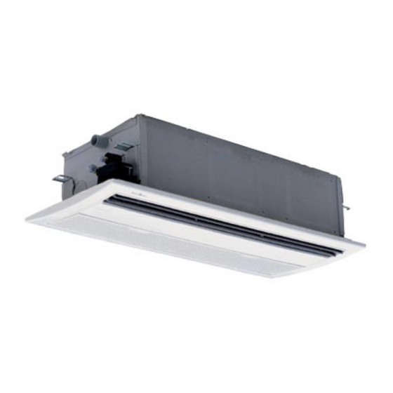
- Page 1 TECHNICAL & SERVICE MANUAL CASSETTE TYPE AIR-CONDITIONER (One-way cassette) FSK-94HF FI-SM-040830...
- Page 2 One-way Cassette Air-conditioner Table of Contants Part 1. Product Features Part 2. Specification Part 3. Noise Level Part 4. Velocity ﹠ temperature distribution Part 5. Operation Range Part 6. Capacity Table Part 7. Outlines and Dimension Part 8. Electric Control Functions Part 9.
-
Page 3: Part 1. Product Features
Part 1. Product Features 1) Lower noise level 2) Smoother air flow with less turbulence ---Owing to the multiple-blade fan rotor and the air guide design, the airflow is getting smoother and more comfortable 3) One direction air flow ---Quick cooling 4) Stylish design ---Be harmonious with any interior decoration and creates an elegant environment 5) Ultra thin machine body... -
Page 4: Part 2. Specification
Part 2. Specification FSK-94HF Model Power supply V-Hz-Ph 220-240V~,50,1 Capacity Btu/h 9000 Capacity 2.65 Cooling Input 1098 Rated current 4.87 Btu/w.h 2,42 Capacity Btu/h 10000 Capacity 2,95 Heating Input 1102 Rated current 4.84 Btu/w.h 2,68 Moisture Removal Max. input consumption 1320 Max. - Page 5 Dimension (W*H*D)(body) 850x235x400 Packing (W*H*D)(body) 1080x310x460 Dimension (W*H*D)(panel) 1050x18x470 Indoor unit Packing (W*H*D)(panel) 1120x172x540 Net/Gross weight(body) 23/27 Net/Gross weight(panel) Model YDK25-6C Brand Welling Outdoor fan Input motor Capacitor 2.5uF/450V Speed r/min Number of rows Tube pitch(a)x row pitch(b) 25.4x22 Fin spacing Outdoor Fin type (code) Hydrophilic aluminium...
-
Page 6: Part 3 Noise Level
Part 3 Noise Level ONE-WAY CASSETTE TYPE 1. 0m Microphone Audibility limits of continuous white sound Octave band center frequency ( Hz )... -
Page 7: Part 4. Velocity ﹠ Temperature Distribution
Part 4 Velocity ﹠ temperature distribution Airflow velocity Temperature... -
Page 8: Part 5 Operation Range
Part 5 Operation Range Ensure the operating temperature is in allowable range. Cooling only Heat pump... -
Page 9: Part 6 Capacity Table
Part 6 Capacity Table Model: FSK-94HF COOLING OUTDOOR TEMPERATURE DRY Indoor Conditions 21ºC 25ºC 30ºC 35ºC 40ºC 45ºC 50ºC Total capacity kW 2.51 2.40 2.32 2.18 2.10 2.03 1.97 21ºC D Sensitive capacity kW 2.01 1.92 1.85 1.75 1.68 1.62 1.57... -
Page 10: Part 7 Outlines And Dimension
Part 7 Outlines and Dimension 1. Indoor unit E-parts box 4-Install hanger Drain hole Liquid side Gas side Air outlet fram e Name Drain hole Φ38mm Liquid side Φ6.35 Gas side Φ9.53 2. Outdoor unit FSO-94HF... -
Page 11: Operation Modes And Functions
Part 8. Electric Control Functions 1. Performance Index Item Index Applicable Voltage Range 165-253V~ A/C Frequency 50Hz Working environment temperature -7°C- +45°C 2. Main Parts Introduction 2.1 Indoor Fan High speed and low speed. Breeze speed for anti-cold air. 2.2 Outdoor Fan Only one speed. -
Page 12: Heating Mode
temperature setting and environment temperature) and will be automatically switched over to manual mode 30 minutes later, under which manual mode will be in effective. 3.1.2.3 Under this mode, the buzzer will buzz twice with each lasting 0.5 second at 0.5 interval. During the first 30 minutes of unconditional forced cooling operation, the operation indicator will blink at 0.5Hz. -
Page 13: Cooling Mode
3.2.3.3 Auto fan of indoor fan under heating mode. Condition (T =Indoor Temp.-Setting Temp.) Indoor fan speed Room temp. up T<3 High T>3 Room temp. down T> 1 T<1 High 3.3 Defrost (only available to heating mode) 3.3.1 The defrosting is processed by indoor control board. 3.3.1.1 Defrosting Conditions 3.3.1.1.1 Low temperature defrosting condition: Accumulated operating time when temperature of outdoor heat exchanger coil T3 is below -2°C reaches... -
Page 14: Other Functions
Condition (T=Indoor Temp.-Setting Temp.) Indoor fan speed Temp. up T<4 T>4 High Temp. down T> 1 High T<1 3.5 Dehumidifying Mode 3.5.1 Dehumidifying mode is the cooling operation, under which the indoor fan is high and outdoor fan is low. 3.5.2 Protective condition is actived. -
Page 15: Condensate Pump
4.1.4 Water Level Alarm Lamp When water level is above the alarm level, it will blink at 5Hz. 4.2 Timer Refer to remote controller manual for detail operation. Note: The timer is valid for one operation of the A/C. 4.3 Louver Action It is controlled by relays. -
Page 16: Self-Diagnosis
5.1.5 Anti-cold air protection Only available to heating mode, including heating mode, heating operation under auto mode. 5.1.6 Condenser high temperature protection 5.1.6.1Only available to cooling (incl. cooling mode, cooling operation under auto mode) and dehumidifying mode. 5.1.6.2 Delay protection should be performed when the compressor restarts. 5.1.7 Water level protection 5.2 Self-diagnosis 5.2.1 Indoor unit... -
Page 17: Part 9. Wiring Diagram
Part 9. Wiring Diagram 1. FSK-94HF Indoor Unit C AP1 C N 1- C N 24 FAN 1 XP1~6 XS1~6 KM 1 R T1 R T2 PU M P L N ( 2) 1 KM 1 FSO-94HF Outdoor Unit R ED... -
Page 18: Part 10 Installation
Part 10 Installation 1. Installation place ● A place where there is enough room for installation and maintenance.(Refer to Chart 1) ● The ceiling is structurally sound to hold the Indoor Unit. ● A place that is well ventilated and the influence of weather is the least. ●... -
Page 19: Panel Installation
● Install the hanging bolt into U groove of the hanging tool. Overhang the indoor unit and ensure it is &&level using a level indicator. Hole Outline of Indoor Unit Model Paper 1010 Ceiling Hole Length Panel Fixing Screw Install the ceiling with the screws used to install Model Paper. ●Secure the Model Paper to the down side of Indoor Unit with Screws used to fix panel. - Page 20 (2). Hang the Panel ● Hang the panel at the hook of Indoor Unit left side. Hook Hook Panel Panel (3). Lead the Swing Motor Wire and Remote Controller Wire into the hole at Indoor Unit left side from outside. Electrical Control Box Hole Connectors (white)
-
Page 21: Install Outdoor Unit
● Check if there is any wire or line clipped between the Panel, Indoor Unit and the Ceiling. 4. Install outdoor unit 5. Refrigerant pipe connecting (1) Maximum pipe length Model Max. Length Max. Elevation FSK-94HF/FSO-94HF (2) Piping sizes Model Liquid(mm/inch) Gas(mm/inch) FSK-94HF/FSO-94HF 6.35(1/4) -
Page 22: Piping Connection
(3) Piping connection 1). Measure the necessary length of the connecting pipe, and make it by the following way. a. Connect the indoor unit at first, then the outdoor unit. Bend the tubing in proper way. Do not harm them. CAUTIONS ●... -
Page 23: Test Operation
8. Test operation (1) The test operation must be carried out after the entire installation has been completed. (2) Please confirm the following points before the test operation. The indoor unit and outdoor unit are installed properly. Tubing and wiring are correctly completed. The refrigerant pipe system is leakage-checked. -
Page 24: Part 11 Servicing And Maintenance
Part 11 Servicing and Maintenance 1. Troubles and Solutions If any the following abnormal conditions occur, turn off the power supply immediately. Please contact our dealer. TROUBLES Indicator lamps flash rapidly, after your disconnecting and connecting the unit, the situation is the same. Fuse or circuit breaker work frequently. - Page 25 The transmission symbol does not flash Symptom Checking items Cause Press ON/OFF button, the remote Check if the remote controller When battery out, controlling signals can not be transmitted has run out of power transmission signals can not be sent Temperature display disappear Symptom Checking items...
- Page 26 3. Clean CAUTION: Please turn off your air conditioner and disconnect power supply before cleaning. (1) CLEANING INDOOR UNIT Use a dry to wipe the indoor unit. A cloth dampened with cold water may be used if the indoor unit is too dirty. It is allowed to remove the front panel of indoor unit and clean it with water, and ensure to wipe it up with a dry rag.
-
Page 27: Part 12. Exploded View
Part 12 Exploded view Indoor unit FSK94HF... - Page 28 Part Name Quantity Part Name Quantity Panel frame, assy Seal Plate ,Ass'y Grille Water depth sensor holder Air filter Separating board, pump Panel Rubber washer, pump Swing motor Pump protecting board Up louver Drain Pump Below louver Water depth sensor Control box Left evaporator cover Display board,Ass'y...
- Page 29 FSO-94HF outdoor Part Name Quantity Part Name Quantity Clamp for front net Wire joint Front net Wire joint, 2p Front clapboard connector install board Propeller fan Clamp for wiring Fan Motor Washer for wire joint Holder for fan motor Installation board for E-parts Condenser Liquid pipe valve Rear clapboard...
Need help?
Do you have a question about the FSK-94HF and is the answer not in the manual?
Questions and answers