Sign In
Upload
Download
Table of Contents
Contents
Add to my manuals
Delete from my manuals
Share
URL of this page:
HTML Link:
Bookmark this page
Add
Manual will be automatically added to "My Manuals"
Print this page
×
Bookmark added
×
Added to my manuals
Manuals
Brands
Fisher Manuals
Air Conditioner
FSAIF-BL-91FE3
Service manual
Fisher FSAIF-BL-91FE3 Service Manual
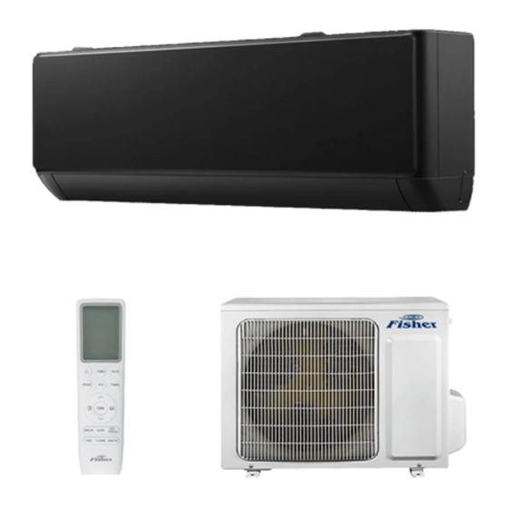
Inverter air conditioner
Hide thumbs
1
Table Of Contents
2
3
4
5
6
7
8
9
10
11
12
13
14
15
16
17
18
19
20
21
22
23
24
25
26
27
28
29
30
31
32
33
34
35
36
37
38
39
40
41
42
43
44
45
46
47
48
49
50
51
52
53
54
55
56
57
58
59
60
61
62
63
64
65
66
67
68
69
page
of
69
Go
/
69
Contents
Table of Contents
Troubleshooting
Bookmarks
Table of Contents
Table of Contents
Part Ⅰ Technical Information
Important Notice
Product Dimension
Refrigeration Cycle Diagram
Wiring Diagram
Electronic Controller Introduction
Electronic Controller
Auto Mode
Cooling Mode
Dry Mode
Heating Mode
Fan Mode
Auto Restart Function
Wifi Operation Maual
PART Ⅱ Installation and Maintenance
Notes for Installation and Maintenance
Safety Precautions Important
Installation Safety
Special Tools
Maintenance
Installation
Installation Dimension Diagram
Accessory
Position
Electricity and Wiring
IDU Installation
Refrigerant Piping Connection
ODU Installation
Electronic Connections
Vacuum and Gas Leakage Test
Final Test
Maintenance
Failure Code
Trouble Shooting
Over / under Voltage Protection
Disassembly IDU & ODU
IDU Disassembly
ODU Assembly
Appendix
Appendix 1 the Comparison Table of Celsius-Fahrenheit Temperature
Appendix 2 the Pipe Length and Gas Charging
Appendix 3 Pipes Flaring
Appendix 4 THERMISTOR TEMPERATURE CHARACTERISTICS
Advertisement
Quick Links
Download this manual
Inverter air conditioner
Service Manual
Models
FSAIF-BL-91FE3/ FSAIF-BL-91FE3
FSAIF-BL-121FE3/ FSAIF-BL-121FE3
FSAIF-BL-181FE3/ FSAIF-BL-181FE3
FI_SM_FSAIF-BL-91-121-181FE3_20240429
Table of
Contents
Previous
Page
Next
Page
1
2
3
4
5
Advertisement
Table of Contents
Need help?
Do you have a question about the FSAIF-BL-91FE3 and is the answer not in the manual?
Ask a question
Questions and answers
Related Manuals for Fisher FSAIF-BL-91FE3
Air Conditioner Fisher FSAI-Pro-91AE2 Service Manual
Room air conditioner split wall-mounted type (66 pages)
Air Conditioner Fisher FSAIF-Pro-95AE2 Service Manual
Split wall-mounted type (53 pages)
Air Conditioner Fisher FSAIF-Pro-93AE2 Service Manual
(69 pages)
Air Conditioner Fisher FSAIF-Pro-94AE2 Service Manual
Split wall-mounted type (52 pages)
Air Conditioner Fisher FSAIF-SU-182AE2 Service Manual
Room air conditioner split wall-mounted type (54 pages)
Air Conditioner Fisher FSAI-SU-92AE2 Service Manual
Room air conditioner split wall-mounted type (54 pages)
Air Conditioner Fisher FSAIF-CP-91AE3 Technical Manual
Split wall-mounted type (55 pages)
Air Conditioner Fisher FSAIF-CP-121AE3 Technical Manual
Split wall-mounted type (55 pages)
Air Conditioner Fisher FSAIF-CP-181AE3 Technical Manual
Split wall-mounted type (55 pages)
Air Conditioner Fisher FSAIF-CP-241AE3 Technical Manual
Split wall-mounted type (55 pages)
Air Conditioner Fisher FSAI-SU-91AE2 Service Manual
Room air conditioner split wall-mounted type (54 pages)
Air Conditioner Fisher FSAIF-BL-121FE3 Service Manual
Inverter air conditioner (69 pages)
Air Conditioner Fisher FSAIF-BL-181FE3 Service Manual
Inverter air conditioner (69 pages)
Air Conditioner Fisher FSAI-CP-120BE3 Service Manual
Split wall-mounted type (113 pages)
Air Conditioner Fisher FSAI-CP-180BE3 Service Manual
Split wall-mounted type (113 pages)
Air Conditioner Fisher FSAI-SU-121AE2 Service Manual
Room air conditioner split wall-mounted type (54 pages)
This manual is also suitable for:
Fsaif-bl-121fe3
Fsaif-bl-181fe3
Table of Contents
Print
Rename the bookmark
Delete bookmark?
Delete from my manuals?
Login
Sign In
OR
Sign in with Facebook
Sign in with Google
Upload manual
Upload from disk
Upload from URL


Need help?
Do you have a question about the FSAIF-BL-91FE3 and is the answer not in the manual?
Questions and answers