Sony ICF-M770L Service Manual
Fm/mw/lw pll synthesized
Hide thumbs
Also See for ICF-M770L:
- Operating instructions (2 pages) ,
- Operating instructions manual (22 pages)
Table of Contents
Advertisement
ICF-M770L/M770S/M770SL
SERVICE MANUAL
Ver 1.1 2002.06
Sony Corporation
9-873-657-02
2002F0500-1
Personal Audio Company
C 2002.06
Published by Sony Engineering Corporation
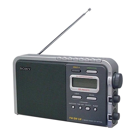
Photo: ICF-M770SL
SPECIFICATIONS
Time display: 24-hour system
Frequency range:
Band
ICF-M770L ICF-M770S
ICF-M770SL Channel
FM
87.5 –
87.5 –
87.5 –
108 MHz
108 MHz
108 MHz
SW
—
5 800 –
5 800 –
15 900 kHz
15 900 kHz
MW
531 –
531 –
—
1 602 kHz 1 602 kHz
LW
153 –
—
153 –
279 kHz
279 kHz
Speaker: 12 cm (4
3
⁄
inches), 8 Ω
4
Power output: 350 mW (at 10% harmonic
distortion)
Output: v (earphone) jack (ø 3.5 mm minijack)
Power requirements:
220–230 V AC, 50Hz
6 V DC, four R20 (size D) batteries
Dimensions:
Approx. 277 × 156 × 71.5 mm (w/h/d)
(Approx. 11 × 6
1
⁄
× 2
7
⁄
inches) incl. projecting
4
8
parts and controls
Mass: Approx. 1 540 g (3lb 6 oz ) incl. batteries
Supplied accessories: AC power cord (1)
Design and specifications are subject to change
without notice.
FM/MW/LW PLL SYNTHESIZED
FM/SW/MW PLL SYNTHESIZED
FM/SW/LW PLL SYNTHESIZED
Italian Model
East European Model
step
0.05 MHz
5 kHz
9 kHz
9 kHz
AEP Model
ICF-M770L/M770SL
UK Model
ICF-M770L
ICF-M770S
ICF-M770L
ICF-M770S
ICF-M770SL
Advertisement
Table of Contents

Related Manuals for Sony ICF-M770L


Summary of Contents for Sony ICF-M770L
- Page 1 Supplied accessories: AC power cord (1) Design and specifications are subject to change without notice. ICF-M770L FM/MW/LW PLL SYNTHESIZED ICF-M770S FM/SW/MW PLL SYNTHESIZED ICF-M770SL FM/SW/LW PLL SYNTHESIZED Sony Corporation 9-873-657-02 2002F0500-1 Personal Audio Company C 2002.06 Published by Sony Engineering Corporation...
-
Page 2: Table Of Contents
LINE WITH MARK 0 ON THE SCHEMATIC DIAGRAMS AND IN THE PARTS LIST ARE CRITICAL TO SAFE OPERATION. REPLACE THESE COMPONENTS WITH SONY PARTS WHOSE PART NUMBERS APPEAR AS SHOWN IN THIS MANUAL OR IN SUPPLEMENTS PUB- LISHED BY SONY. -
Page 3: General
To set the current time exactly to the second, adjust Legen Sie die Batterien mit dem Minuspol the minute and then press mb/CLOCK (CLOCK for zuerst ein. ICF-M770L) to synchronize with a time signal (such Inserte primero el lado de la pila. as the telephone time signal). -
Page 4: Disassembly
ICF-M770L/M770S/M770SL SECTION 3 DISASSEMBLY • This set can be disassembled in the order shown below. 3-1. DISASSEMBLY FLOW 3-2. CABINET (REAR) ASSY (page 4) 3-3. CHASSIS ASSY (page 5) 3-4. MAIN BOARD (page 5) Note: Follow the disassembly procedure in the numerical order given. -
Page 5: Chassis Assy
ICF-M770L/M770S/M770SL 3-3. CHASSIS ASSY 4 chassis assy 1 knob (jog) 2 knob (control) (vol) 3 knob (control) (tone) 3-4. MAIN BOARD 5 main board 4 claw 3 key board 4 three claws 1 two screws (P2 × 8) 2 claw... -
Page 6: Electrical Adjustments
ICF-M770L/M770S/M770SL SECTION 4 ELECTRICAL ADJUSTMENTS no mark : common 0 dB=1 µV ) : ICF-M770L ] : ICF-M770S [MW/LW] 〈〈 〉〉 : ICF-M770SL Setting: BAND switch: MW or LW AM IF ADJUSTMENT Adjust for a maximum reading on level meter... - Page 7 ICF-M770L/M770S/M770SL Adjustment Location: – MAIN BOARD (Component Side) – L10 MW VT Voltage Adjustment (M770S) LW VT Voltage Adjustment (M770SL) LW VT Voltage Adjustment (M770L) L8 MW VT Voltage Adjustment (M770L) SW VT Voltage Adjustment (M770S/M770SL) CT1 SW Tracking Adjustment (M770S/M770SL)
-
Page 8: Diagrams
ICF-M770L/M770S/M770SL SECTION 5 DIAGRAMS 5-1. BLOCK DIAGRAM ANT1 FM/SW ANTENNA CT4, L12, 13 FM TRACKING B.P.F. L12, 13 • SIGNAL PATH BPF1 FM RF : FM FM/AM FRONT-END, M770S/ FM/AM IF AMP, DET, AGC, AF AMP M770SL : MW/LW SWITCH... -
Page 9: Schematic Diagrams
ICF-M770L/M770S/M770SL 5-2. NOTE FOR PRINTED WIRING BOARD AND SCHEMATIC DIAGRAMS • Circuit Boards Location Note on Printed Wiring Board: Note on Schematic Diagram: • X : parts extracted from the component side. • All capacitors are in µF unless otherwise noted. pF: µµF •... -
Page 10: Printed Wiring Boards - Main/Jack/Power/Inlet Boards
ICF-M770L/M770S/M770SL 5-3. PRINTED WIRING BOARDS – MAIN/JACK/POWER/INLET Boards – • See page 9 for Circuit Boards Location. L5-1 L5-2 MW/LW FERRITE-ROD (M770S/M770SL) MW FERRITE-ROD LW FERRITE-ROD ANTENNA ANTENNA ANTENNA (M770L) MAIN BOARD ANT1 (M770L) (M770S/M770SL) (ANT) (M770L) JW13 BPF1 JACK BOARD... -
Page 11: Main/Jack/Power/Inlet Boards
ICF-M770L/M770S/M770SL 5-4. SCHEMATIC DIAGRAM – MAIN/JACK/POWER/INLET Boards – • See page 9 for IC Block Diagram. JW14 JW17 100k (M770S) (M770SL) (M770L) (M770L) (M770S/M770SL) SW/MW OSC (M770S/M770SL) 220µH DTA144TUA ∗ ∗ ∗ SW SWITCH 3.3k (M770L) (M770L) (M770L) 2SC4098 (M770L) -
Page 12: Printed Wiring Board - Key Board
ICF-M770L/M770S/M770SL 5-5. PRINTED WIRING BOARD – KEY Board – • See page 9 for Circuit Boards Location. • Semiconductor Location Ref. No. Location KEY BOARD D101 D102 S108 S107 S106 S105 S104 S103 S102 S101 D103 R147 D104 D105 D106... -
Page 13: Schematic Diagram - Key Board
ICF-M770L/M770S/M770SL 5-6. SCHEMATIC DIAGRAM – KEY Board – • See page 14 for Waveforms. UCOM DC 6V COM Q101 VOLTAGE VOLTAGE 2SB970 B+ SWITCH +3V REGULATOR DETECT DETECT IC101 IC102 IC103 R103 R104 S-81230SG-QB-T1 S-80836ANNP S-80842ANNP 4.7k Q109 2SA1576A Q102... -
Page 14: Ic Pin Function Description
Beep sound drive signal output VDET2 Voltage detection signal input “L”: 2.9V or less INITIAL1 Model setting input terminal “L”: ICF-M770L, “H”: ICF-M770S/M770SL INITIAL2 Model setting input terminal “L”: ICF-M770L/M770S, “H”: ICF-M770SL AM/(FM/TV) Band selection signal output “L”: FM, “H”: SW/MW/LW... -
Page 15: Exploded Views
KNOB, BALANCE (WHITE) . . . (RED) trical parts list. ↑ ↑ • When “NET, SPEAKER (Ref. 3)” is being Parts Color Cabinet's Color replaced, “EMBLEM (5-A), SONY (Ref. 5)” needs to be replaced also. 6-1. CABINET (FRONT) SECTION cabinet (rear) section chassis section Ref. No. -
Page 16: Cabinet (Rear) Section
ICF-M770L/M770S/M770SL 6-2. CABINET (REAR) SECTION ANT1 supplied supplied T202 The components identified by mark 0 or dotted line with mark 0 are critical for safety. Replace only with part number specified. Ref. No. Part No. Description Remark Ref. No. Part No. -
Page 17: Chassis Section
ICF-M770L/M770S/M770SL 6-3. CHASSIS SECTION LCD101 main board supplied supplied key board Ref. No. Part No. Description Remark Ref. No. Part No. Description Remark * 101 A-3021-849-A KEY BOARD, COMPLETE (M770SL) 3-237-023-01 CHASSIS * 101 A-3021-855-A KEY BOARD, COMPLETE (M770S) * 107... -
Page 18: Electrical Parts List
ICF-M770L/M770S/M770SL SECTION 7 ELECTRICAL PARTS LIST INLET JACK NOTE: • Due to standardization, replacements in the • Items marked “*” are not stocked since they The components identified by parts list may be different from the parts speci- are seldom required for routine service. - Page 19 ICF-M770L/M770S/M770SL Ref. No. Part No. Description Remark Ref. No. Part No. Description Remark C150 1-162-923-11 CERAMIC CHIP 47PF C151 1-104-396-11 ELECT 10uF R111 1-216-845-11 METAL CHIP 100K 1/10W C152 1-164-227-11 CERAMIC CHIP 0.022uF R112 1-216-829-11 METAL CHIP 4.7K 1/10W R113...
- Page 20 ICF-M770L/M770S/M770SL MAIN Ref. No. Part No. Description Remark Ref. No. Part No. Description Remark R165 1-216-833-11 METAL CHIP 1/10W R166 1-216-833-11 METAL CHIP 1/10W S120 1-571-850-91 SWITCH, SLIDE (HOLD) R167 1-216-833-11 METAL CHIP 1/10W < TRANSFORMER > R168 1-216-833-11 METAL CHIP...
- Page 21 ICF-M770L/M770S/M770SL MAIN Ref. No. Part No. Description Remark Ref. No. Part No. Description Remark 1-162-927-11 CERAMIC CHIP 100PF < TRIMMER > (M770SL) 1-164-392-11 CERAMIC CHIP 390PF 1-141-601-11 CAP, ADJ 10PF (M770S) 1-141-622-11 CAP, ADJ 50PF (M770L/M770SL) 1-162-925-11 CERAMIC CHIP 68PF...
- Page 22 ICF-M770L/M770S/M770SL Ver 1.1 MAIN POWER Ref. No. Part No. Description Remark Ref. No. Part No. Description Remark 8-729-028-92 TRANSISTOR DTA144TUA-T106 (M770S/M770SL) 1-216-829-11 METAL CHIP 4.7K 1/10W 8-729-029-15 TRANSISTOR DTC144TUA-T106 1-216-841-11 METAL CHIP 1/10W (M770S/M770SL) 1-216-817-11 METAL CHIP 1/10W 8-729-054-77 TRANSISTOR...
- Page 23 ICF-M770L/M770S/M770SL MEMO...
- Page 24 ICF-M770L/M770S/M770SL REVISION HISTORY Clicking the version allows you to jump to the revised page. Also, clicking the version at the upper right on the revised page allows you to jump to the next revised page. Ver. Date Description of Revision 2002.03...
Need help?
Do you have a question about the ICF-M770L and is the answer not in the manual?
Questions and answers