Table of Contents
Advertisement
Advertisement
Table of Contents

Related Manuals for Telstrom DF-A-S-1B

Summary of Contents for Telstrom DF-A-S-1B
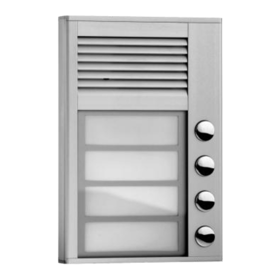
- Page 1 Analogue Slender DoorPhone DF-A-S-1B DF-A-S-2B DF-A-S-4B User´s manual...
-
Page 2: Table Of Contents
Contents BASIC DESCRIPTION ..................3 ...................... 3 EATURES ..................4 LENDER MODELS INSTALLATION ....................4 ........4 PENING WIRING WALL MOUNTING AND SETTINGS 2.1.1 Name card panel ..................4 2.1.2 Uncover control elements ................. 5 2.1.3 Wiring and wall mounting ................ 5 2.1.4 Switches .................... -
Page 3: Basic Description
Basic description 1.1 Features Very low profile for surface mounting only. Supplied in 1, 2 or 4 button variants. Voice communication powered from an analogue telephone line. Pulse and tone (DTMF) dial Two 16 digits numbers saved under each button (includes *, #, RECALL and pause) ... -
Page 4: Slender Models
1.2 Slender models Three versions are available : DF-A-S-1B 1 button DF-A-S-2B 2 button DF-A-S-4B 4 buttons 2 Installation This compact unit is fixed by 2 screws to the wall. 2.1 Opening, wiring, wall mounting and settings 2.1.1 Name card panel 1. -
Page 5: Uncover Control Elements
2.1.2 Uncover control elements 4. Push the aluminium speaker grille down (see figure – 4). 2.1.3 Wiring and wall mounting 5. Use wall mounting template at the end of the manual to mark the position for the screw holes and cable connection on the mounting surface. -
Page 6: Switches
(central) and "NC" means contact normally closed. The relay contact is isolated from the other circuits on the board. For the variants of lock connection see the picture below. Telephone line Power supply lock Wiring of standard magnetic (inverse) lock 7. -
Page 7: Voice Level
The PCB heating has two major benefits. Firstly, it warms the board during winter time (temperatures under -20 C, most circuits have warranty operation down to -20 C) and secondly it helps to protect the PCB against humidity when installed outside. 2.1.5 Voice level 10. -
Page 8: Location Of Doorphone Components
2.2 Location of Doorphone components All mounting, control and setting elements are located under the speaker front aluminium grille. SPK- setting of Loudspeaker MIC-setting speaker volume microphone volume Service switch TRH – setting of microphone PC connector activation level Heating activation SlenderPhone fixing screw... -
Page 9: Changing Name Cards
2.3 Changing name cards pocket Name card panel (2.1.1on page 4) has spaces to insert printed name cards. Insert name cards from top (see picture). Cards can easily be printed with pictures as well as text using the included software. The card outline is marked for easy cutting . Panel with cards 2.4 Final closing of Doorphone... -
Page 10: Slenderdoorphone Services
3 Slender Door Phone Services 3.1 Signalling Overview The unit signals acoustic conditions that may occur during operation. You can listen to the signalling samples in the ID Manager program. Condition Tones Tone frequency –▄–■–▀– Pick up line 425-850-1275 –▀–■–▄ Hang up line 1275-850-425 ––█––... -
Page 11: Telephone Caller
from the second group (parameter 2). The next press of the same button again selects the number from the first group, etc..…… If the button is pressed after the line has been opened (but before the call is answered), the unit will hang up for the period given by parameter 54, lift up the line and dial the other group number. -
Page 12: Parameter Programming
4 Parameter programming 4.1 Programming from a telephone by DTMF 4.1.1 Entering programming mode The Slender Door Phone may be set to programming mode in two ways: 1. by password – dial the unit„s number (either extension number, if . The connected to a PBX or telephone number, if connected to a PSTN line) unit will answer (you will hear the Pick up line tone –... -
Page 13: Programming From Apc - Id Manager Program
Note 1. if you wish to maintain the connection in programming mode (i.e. extend the 34 seconds period) then it is necessary to occasionally press a key (e.g. , # or 7). The unit will respond with an error tone but the connection will be kept alive. Note 2. -
Page 14: Parameter Description
Parameter description 5.1 Direct Dialling – Memories Parameter Value Description Default Exam.1 Exam.2 t nn… No. nn under button t t – Button number (memory) [1-4] nn – telephone number up to 16 digits to be stored. parameter dial Refer to the table for other choices. 0 - 9 0 - 9 The number stored in parameter 1 is the number for the... - Page 15 Parameter Value Description Default Exam.1 Exam.2 External access code in hhhhhh 1212 1324 DAY + NIGHT mode External access code in hhhhhh 2211 2211 DAY mode External access code in hhhhhh 1122 1122 NIGHT mode hhhhhh – password for relay closing from buttons [2 to 6 digits] The 3 passwords are controlled by Day/Night;...
-
Page 16: Basic Parameters
Parameter Value Description Default Exam.1 Exam.2 Internal access code 2 impulses cc – command from phone to relay closing [2 digits] – 2 impulses Parameter Value Description Default Exam.1 Exam.2 External access code in hhhhhh DAY + NIGHT mode for 2 impulses hhhhhh –... -
Page 17: Time Parameters
xxxx 0000 0000 0000 Password xxxx – service password for entry to programming Parameter Value Description Default Exam.1 Exam.2 DAY MODE switching NIGHT MODE switching dd – command for DAY switching [2 digits] MODE nn – command for NIGHT switching [2 digits] MODE Note: The switchover to Day/Night mode remains set in unit even after line disconnection. - Page 18 Parameter Value Description Default Exam.1 Exam.2 time between button presses w – max. time [sec] between button presses [range 1-9] relay closing – if time between two next presses is bigger than w time, the code is not evaluated correctly. dialling –...
- Page 19 Parameter Value Description Default Exam.1 Exam.2 DTMF tone duration (ms) (100ms) (100ms) (100ms) Space duration between DTMF tones (ms) (100ms) (100ms) (100ms) Recall duration (ms) (100ms) (100ms) (100ms) Pause duration (ms) (800ms) (800ms) (800ms) – DTMF tone duration is determined by the formula: (entered number + 5) x 10 = tone duration [ms] [range 1-0 i.e.
-
Page 20: Presetting And Deleting
Parameter Value Description Default Exam.1 Exam.2 Frequency of tone detection y – setting range frequency of tone detection from telephone line, value is in next table: frequency range frequency range 200-350Hz 500-650Hz 250-400Hz 550-700Hz 300-450Hz 600-750Hz 350-500Hz 650-800Hz 400-550Hz 700-850Hz 450-600Hz 750-900Hz Parameter Value... -
Page 21: Exit Programming
Parameter Value Description Default Exam.1 Exam.2 Deletes all numbers in group 1 (Day mode) Deletes all numbers in group 2 (Night mode) Default setting only only 3.. for parameters 3x Default setting only only 4.. for parameters 4x Default setting only only 5.. -
Page 22: Overview Of Parameters
Parametr Value Description Default Exam.1 Exam.2 3 and 9 3 and 9 3 and 9 Acoustic signalling In default the unit produces acoustic signals. It can occasionally cause a problem of incorrect detection of tones by PBX. By changing parameter „z“ you can switch off this acoustic signalization. - Page 23 Relay closing time Time between 2 impulses Internal access code 2 impulses External access code in hhhhhh DAY + NIGHT mode for 2 impulses Dialling type Extending call End call xxxx 0000 0000 0000 Password DAY MODE switching NIGHT MODE switching Dialling mode Number of rings before pick-up...
-
Page 24: Technical Parameters
Delay of line connection (Siemens PBX) 3 and 9 3 and 9 3 and 9 Acoustic signalling executes Default setting executes Setting per exam. 1 executes Setting per exam. 2 Deletes all numbers in group 1 (Day mode) Deletes all numbers in group 2 (Night mode) Default setting only only 3.. -
Page 25: Mechanical Dimensions
switches and heating Max. consumption of lighting 300mA through and heating Max. voltage of switch contact at I < 1A Max. current of switch contact at U < 30 V Operational temperature - 20 to + 50°C 6.2 Mechanical dimensions Dimensions WxHxD 104mm x 153mm x 16mm Weight... - Page 26 Internal access code Relay closing time [sec] Time between 2 impulses [sec] Internal access code 2 impulses External access code Day+Night 2 impulses Dialling type 1 / 0 Prolong call End call Password DAY MODE switching NIGHT MODE switching Dialling mode 1 / 0 No.
-
Page 27: Drilling Master Board
8 Drilling master board...
Need help?
Do you have a question about the DF-A-S-1B and is the answer not in the manual?
Questions and answers