Advertisement
ASSEMBLY INSTRUCTIONS
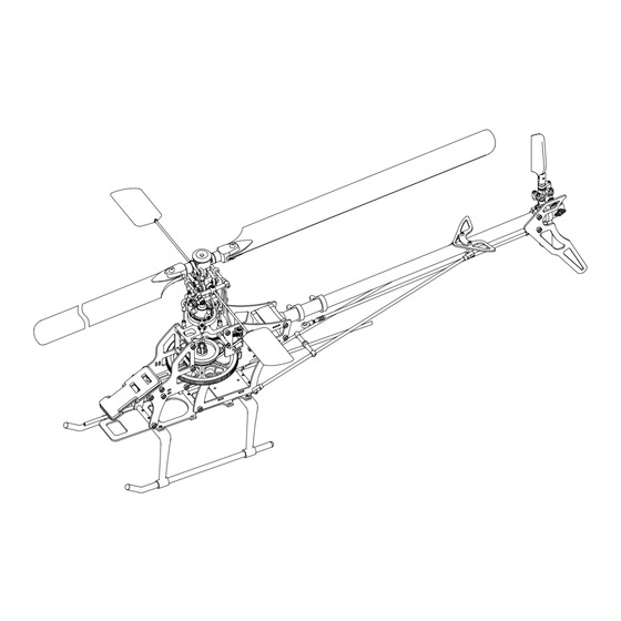
Specifications
Length
Height
Main Blade
Main Rotor Diameter
Tail Rotor Diameter
Motor Pinion Gear
Main Drive Gear
Main Drive Pulley
Tail Pulley
Weight (w/o main blades) : 420g
Flying Weight
Drive Gear Ratio = 1:10.71:4.63 (1:9.37:4.63)
: 660 mm
: 218 mm
: 325 mm
: 723 mm
: 150 mm
: 16T (14T)
: 150T
: 51T
: 11T
: Approx. 880g
MADE IN KOREA
6/2007
Advertisement

Related Manuals for Beam E4

Summary of Contents for Beam E4
-
Page 1: Assembly Instructions
ASSEMBLY INSTRUCTIONS Specifications Length : 660 mm Height : 218 mm Main Blade : 325 mm Main Rotor Diameter : 723 mm Tail Rotor Diameter : 150 mm Motor Pinion Gear : 16T (14T) Main Drive Gear : 150T Main Drive Pulley : 51T Tail Pulley : 11T... -
Page 2: Table Of Contents
·················· Table of contents ·················· 1. Read before assembly ····························· 1 2. Safety guidelines for the R/C helicopter ····························· 2 Additional items & Tools needed ····························· 4 3. Assembly ····························· 5 4. Pitch and Throttle setting ···························· 16 5. Transmitter Sticks and Unit Movement ····························... -
Page 3: Safety Guidelines For The R/C Helicopter
Safety Guidelines for the R/C Helicopter 1. Beginners should get guidance and supervision from experienced flyers. 2. Fly only at approved airfields. Do not fly at school, residential area or near roads, railways and power lines. 3. Make sure there are no other pilots flying with the same radio frequency as yours. Interference can be very dangerous to all. - Page 4 2-2. During the flight 1. We strongly recommend you to spend time in practicing the helicopter simulation program before you fly the real model. This will get you confidence and will significantly reduce the cost of repair. Keep practicing the simulation program and that will accelerate your learning curve. 2.
- Page 5 Additional items needed (sold separately). 1. Transmitter 2. Receiver 3. Servo 4. Gyro 5. Motor 6. Electronic speed controller 7. Lipo Battery 8. Battery charger Tools required for assembly Hex wrench (2mm, 3mm) Screw driver (Small, Large) Ball link plier Ball reamer Long nose plier Pitch gauge...
-
Page 6: Assembly
Assembly : Use Cyano Adhesive : Use Blue Locktite : Use Red Locktite Blue 2 pcs 26 pcs Socket Head Bolt, 2x6mm Flat Head Bolt, 2x8mm 1 pc 1 pc 2 pcs 2 pcs Ball Bearing, #685zz Ball Bearing, #MR115zz Socket Head Bolt, 2x25mm Ball Bearing, #MR52zz Main Mast Block, Belt Guide Pulley... - Page 7 10 pcs 2 pcs 2 pcs Self Tapping Screw, 2x7mm Socket Head Bolt, 2x5mm Flat Head Bolt, 2x6mm 2 pcs 4 pcs Socket Head Bolt, 2x6mm Flat Head Bolt, 2x8mm Main Frame Bottom Plate, Landing Skid Self Tapping Screw, Crossmember, 2x7mm (4 pcs) 30mm (3 pcs) Main Frame...
- Page 8 6 pcs 3 pcs 1 pc Countersunk Screw, 2x7mm Flat Head Bolt, 2x3.5mm Ball Bearing, #MR106zz 1 pc 1 pc 6 pcs Countersunk Screw, 2x14mm Flat Head Bolt, 2x5mm 1 pc 1 pc 1 pc Ball Bearing, #HF0612zz Ball Bearing, #6704zz Socket Head Bolt, 2x11mm Nut, 2mm Swashplate, Main Drive Gear...
- Page 9 12 pcs 2 pcs 1 pc 8 pcs Ball Bearing, #MR52zz Set Screw, 3x3mm Socket Head Bolt, 2x4mm Countersunk Screw, 2x7mm 1 pc 2 pcs 1 pc 2 pcs Nut, 2mm Socket Head Bolt, 2x11mm Countersunk Screw, 2x8mm Ball Bearing, #MR63zz 4 pcs 2 pcs 2 pcs...
- Page 10 13.5 13.5 4 pcs Socket Head Bolt, 2x8mm 2 pcs 2 pcs 29.2 Washout Arm To Flybar Arm Spacer Set Screw, 3x3mm (Linkage Rod 1.3x12mm) Flybar Control Arm Set Screw, 3x3mm (2 pcs) Socket Head Bolt, 2x8mm (4 pcs) Flybar Arm Spacer Blue Linkage Rod, Flybar, 210mm...
- Page 11 Ball Link (S), Ball Link (L), Use Ball Link Tool 11.5mm (2 pcs) 13.5mm (16 pcs) 13.5 11.5 13.5 13.5 11.5 13.5 2 pcs 2 pcs 48.3 Main Blade Holder To Seesaw Mixing Arm Seesaw Mixing Arm To Swashplate Cap (Linkage Rod, 1.3x10mm) (Linkage Rod, 1.3x33mm) 13.5...
- Page 12 8 pcs 2 pcs 2 pcs 2 pcs Socket Head Bolt, 2x7mm Flat Head Bolt, 2x3.5mm Countersunk Screw, 2x7mm Ball Bearing, #MR74zz 4 pcs 3 pcs 2 pcs Flat Head Bolt, 2x6mm Countersunk Screw, 2x10mm Ball Bearing, #MR52zz 2 pcs 2 pcs 3 pcs 1 pc...
- Page 13 2 pcs 8 pcs 2 pcs Self Tapping Screw, 2x7mm Socket Head Bolt, 2x8mm Socket Head Bolt, 2x13mm Tail Drive System Clockwise Caution Mind the direction Twist (90° ) of the Drive Belt. Self Tapping Screw, 2x7mm (2 pcs) Horizontal Fin Socket Washer Tail Boom, (2 pcs)
- Page 14 Main Drive Gear Assembly Main Mast Main Mast Lock...
- Page 15 Motor Pinion Gear & Etc. 1 pc Set Screw, 3x3mm 2 pcs Socket Head Bolt, 3x15mm 2 pcs Nylon Nut, 3mm Motor Pinion Gear Set Screw, 3x3mm (1 pc) Main Blade, 325mm Socket Head Bolt, 3x15mm (2 pcs) Nylon Nut, 3mm (2 pcs) Rubber Body Canopy Mounting...
-
Page 16: Pitch And Throttle Setting
Pitch and Throttle settings 4-1. Pitch Range setting ⓐ Check that no data has been input into the pitch curve function of the transmitter. If any data has been input, delete it. ⓑ Adjust the length of the pitch linkage rods so that the main blade pitch is 0˚ when the transmitter throttle stick is in the mid position. - Page 17 4-3. Pitch curve setting Adjust the transmitter's pitch curve so that you can get the pitch angles shown in the table below in the low, mid and high positions of the throttle stick. ⓐ Beginner Throttle stick position High Remarks Flight mode Hovering -1 (46%) ★...
- Page 18 4-5. Throttle curve settings on the transmitter ⓐ Beginner 0% 75% Hovering ST1 (Loop,Roll) ST2 (3D) Autorotation ⓑ Expert 0% 95% Hovering ST1 (Loop,Roll) ST2 (3D) Autorotation...
- Page 19 Movement of Transmitter Sticks and the Heli Make sure that movement of the heli follows movement of the transmitter sticks in the way described below. Aileron Right Left Elevator Down Rudder Right Left Trottle Down...
-
Page 20: Data Sheet, 120˚ Ccpm
Steps should be taken before flying ① Extend the transmitter antenna. ② Put the throttle stick of the transmitter at low position and then turn on the transmitter. ③ Put the hold key at on position. (This will prevent the main rotor from rotating abruptly in case that you put the throttle stick at high position inadvertantly). -
Page 21: Tracking Adjustment
Tracking adjustment ① Measure the pitch angle using a pitch gauge and make the angle same on both sides of the main rotor by adjusting the mixing arm control rod. ② Apply the tracking tape to one of the rotor blades. ③...
Need help?
Do you have a question about the E4 and is the answer not in the manual?
Questions and answers