Table of Contents
Advertisement
Subject: ATR110 Manual
Prepared by: Andrew Covey
Authorised by: Nigel Bonsor
Revision: 1.2
Issue Date: 21/09/2015
Product names
mentioned herein are for
identification purposes
only and may be
trademarks and/or
registered trademarks of
their respective
companies.
© Copyright 2015
ALL RIGHTS
RESERVED
Access IS
18 Suttons Business Park, Reading
Berkshire, RG6 1AZ, United Kingdom
Tel. +44 (0) 118 966 3333
www.access-is.com
ATR110
1D and 2D Barcode Imager
(Version - Barcode Only)
Product Manual and
User Guide
Access (North America) Inc
Atlanta, Georgia,
USA
Tel: +1-770-645-2771
Email: sales@access-is.com
Advertisement
Table of Contents

Related Manuals for Access IS ATR110


Summary of Contents for Access IS ATR110
- Page 1 ATR110 Subject: ATR110 Manual Prepared by: Andrew Covey 1D and 2D Barcode Imager Authorised by: Nigel Bonsor Revision: 1.2 (Version - Barcode Only) Issue Date: 21/09/2015 Product names Product Manual and mentioned herein are for identification purposes User Guide only and may be...
- Page 2 Typographical Update Warnings This manual contains important information regarding the installation and operation of the ATR110 2D Barcode Imager. For safe and reliable operation of the imager, installers must ensure that they are familiar with and fully understand all instructions contained herein.
-
Page 3: Table Of Contents
Barcode Engine/Imager Command Reference ..............20 Basic Configuration ..................... 20 Prefix/Suffix Solutions ....................21 ATR Illumination ......................22 Indicators ........................24 ATR110 LED/Sounder Control ..................26 Development Commands .................... 30 Triggering ........................31 Counter ........................32 Appendices ........................33 HID Reports ........................ 33 Hex Character Reference .................... -
Page 4: Overview
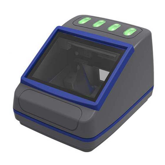
1. Overview The ATR110 is a compact and fast barcode reader with optional NFC contactless capabilities. This ‘one-box’ solution helps process a wide range of electronic ticketing across a variety of media. The device is designed to read all popular linear, PDF417 and 2D barcode symbologies, including QR and Aztec codes, from smartphones, tablets and printed paper documents. -
Page 5: Specifications
2. Specifications Specification Dimensions: 12cm x 10cm x 8cm (LxHxW) Weight 400g (without NFC); 520g (with NFC) Environmental: Operating temperature -25º to 50ºC Storage temperature -30º to 70ºC Designed to meet IP54 Colour: Dark Grey with Blue Rubber Smartphone Bumper Glass: 3mm toughened low-iron Conturan IK07 (3 times 2J impact) Buzzer:... -
Page 6: Installation
3. Installation 3.1 Connection The ATR110 is connected directly to an RS232 port or USB port. (Standard supplied cable length is 1.8m although other options are available for pole mounting etc.) 3.1.1 Connection to RS232 To COM: Serial and Power Cable... -
Page 7: Mounting
3.2 Mounting The ATR110 is designed for simple installation; the dimensions of the unit are below. For optimum performance the ATR110 should not be positioned in direct sunlight. 3.2.1 Mounting Details – ATR110 Copyright © Access-IS 2015 Page 7 of 39... -
Page 8: Connection Options
3.3.2.2 HID Interface Access IS recommend the use of the HID interface for reliability – for example, a CDC interface may not recover properly in the event of accidental disconnects or power fluctuations where a HID interface will. - Page 9 3.5.2 Custom HID 3.5.2.1 Access Serial Driver (Windows Only) The recommended method for using a USB ATR110 is for the device to be configured into HID mode. This will allow the device to communicate with the Access driver. For this method to operate it is necessary to install the Access driver (Access Serial Ports - ASPS), this can be downloaded from http://downloads.access-is.com (Full instructions are included in the...
- Page 10 Right-click on the device and select “Update Driver Software”. Click on “Browse my computer for driver software”. Copyright © Access-IS 2015 Page 10 of 39...
- Page 11 Use the “Browse” button to select the directory where AccessISUSBCDC.inf has been downloaded. The following screen will appear display the progress of the installation. Copyright © Access-IS 2015 Page 11 of 39...
- Page 12 The device is now ready to be used. It will have been assigned a virtual COM port. You can find out the COM port number by going back into device manager and looking under “ports” - the device will be listed with the COM number alongside it.
-
Page 13: Barcode Engine/Imager Data Format Protocol
If the required format is not listed above, please contact the Access-IS Sales Team for assistance. It is possible to configure the ATR110 to any of the common baud rates, data bit lengths, parity and stop bits. It is also possible to add a range of suffixes and prefixes which are able to be represented as hex characters. -
Page 14: Barcode Engine/Imager Operating Modes
5. Barcode Engine/Imager Operating Modes The ATR110 can operate in one of three ways. Detailed examples can be seen on the following pages; a brief summary is included here. 5.1 Mode Summary 5.1.1 Dumb The ATR is a one way communication device. -
Page 15: Dumb
5.2 Dumb Shown below is a flow chart illustrating the process for a ATR in Dumb mode. Reader Idle Media Detected Imager and Illumination Activated Lights ‘Good Barcode Read Read’ (as Settings Instruct) Data Sent to Host Imager and Illumination Deactivated Reader Idle 5.2.1 Example... -
Page 16: Host
5.3 Host Shown below is a flow chart illustrating the process for an ATR in Host mode. Reader Idle Media Detected Imager and Illumination Activated Barcode Read Data Sent to Host. Imager and Illumination Deactivated Accept or Reject? Reject Accept Ignore Command or No Response within Timeout Lights ‘Bad Read’... - Page 17 5.3.1 Example Accept Comments ATR Command to Host Host Command to ATR Media placed in front of ATR. Imager activated and barcode Data sent as configured (e.g. scanned. Illumination activated USB/serial) as settings. Host decides to accept or reject ‘Good Read’: “AISXXR0” the data.
-
Page 18: Interactive
5.4 Interactive Shown below is a flow chart showing the standard process for an ATR in Interactive mode. As mentioned in the description above the trigger, ‘Good Read’ and “bad read” commands can be sent to the ATR at any time. Reader Idle Media Detected, Message Sent... - Page 19 Example Good Read initiated by ATR detecting media. Comments ATR Command to Host Host Command to ATR Media placed in front of ATR. [0x16][0x0D]TRIG:1[0x16][0x0A] ATR sends commands to host notifying of media. Host sends a command to [0x16][0x74][0x0D] trigger the imager. Imager activated and barcode Data sent as configured (e.g.
-
Page 20: Barcode Engine/Imager Command Reference
6. Barcode Engine/Imager Command Reference Commands are sent with a prefix of [0x16][0x4D][0x0D] causing the command sequence to take the form [0x16][0x4D][0x0D]<Menu Command>. The Menu Commands are six characters long with a parameter (if required). The command is concluded by a dot ‘.’ or an exclamation mark ‘!’. The dot stores the setting permanently and the exclamation mark keeps it temporarily until power is removed from the device. -
Page 21: Prefix/Suffix Solutions
6 - CZ 7 - FR 8 - BE 9 - SE AISCHR Sets inter-character delay. 1-250 - Time in ms Only used when AISINF is set to 2 (USB Keyboard). AISOMD Indicator Mode Setting. 0 - Dumb Mode 1 - Host Mode 2 - Interactive AISTAM Trigger Auto Mode. -
Page 22: Atr Illumination
6.3 ATR Illumination The standard method of reading barcodes cycles the illumination on and off. This can be controlled for various different applications using the commands below. For example, it is often beneficial to turn off the illumination to prevent reflections from shiny surfaces, e.g. mobile phones. Command Description Default... - Page 23 Each unit is equivalent to 100 milliseconds. AISOF2 Illumination off Time 2 - Adaptive mode 0 - 200 Applies to AISILL modes 2 and 3 only. Each unit is equivalent to 100 ms. AISOF3 Illumination off Time 3 - Adaptive mode 0 - 200 Applies to AISILL modes 2 and 3 only.
-
Page 24: Indicators
6.4.2 Status LED The ATR110 contains two small orange LEDs on the main circuit board. These are typically used for debug purposes only. We recommend turning these off in normal use. A typical configuration will have these turned off but the default values will be as below (For Example, when using the AISRDS command). - Page 25 Command Description Default Parameters/Range AISLS1 Status LED function. 0 - None 1 - Power On 2 - Loader 3 - Power On and Loader 4 - Power On Except When Triggered 16 - Brownout Detection (Diagnostic) 32 - Brownout Reset (Diagnostic) 48 - Brownout Status - Detection or Reset...
-
Page 26: Atr110 Led/Sounder Control
LEDs: 6.5.1.1 ‘LSR110’ For those familiar with the Access IS LSR110, this method is the same and is provided to allow backwards compatibility. Only the ‘Good’ and ‘Bad’ LEDs are controllable. In Dumb mode, successfully reading a barcode will cause the Good Read LEDs to illuminate and the Good Read beep to sound. - Page 27 6.5.2 ATR110 New LED/Sounder commands LED Bank 1 is front LED bank, LED Bank 2 is rear LED bank (in desktop orientation). LED locations A - D are left to right (in desktop orientation). Command Description Default Parameters AISLCM LED control...
- Page 28 6.5.3 LED Control Direct Parameter Format The parameter is a 16 character string. The string consists of 8 character pairs, each of which represents the state of an LED. The first 4 pairs represent the LEDs in LED bank 1 (front LEDs in desktop orientation), the remaining pairs represent the LEDs in LED bank 2 (rear LEDs in desktop orientation).
- Page 29 6.5.5 Summary of Valid Sounder Commands Command Description Default Parameters/Range AISGBF Good Beep Frequency 0 - 700Hz 1 - 1400Hz 2 - 2800Hz AISGBD Good Beep active Duration: 0-100 0 - 100 (unit is 100ms) AISGBS Good Beep Silence duration: 0-100 0 - 100 (unit is 100ms) AISGBN...
-
Page 30: Development Commands
Only applicable to interactive mode (AISOMD2). 1 - enabled If this flag is set then the TRIG messages from the ATR110 are sent only on media detect and media removed, regardless of commands from the host. AISRDS Change configuration to default values. -
Page 31: Triggering
6.7 Triggering Command Description Default Parameters/Range AISTUT Automatically Untrigger. 0-25000 AISTMD Convert trigger modes. 0 - Imager must be triggered This is for advanced users only and modification may cause the device to 1 - Imager in presentation become inoperable. mode AISTST Soft Trigger Timeout. -
Page 32: Counter
6.8 Counter Command Description Default Parameters/Range AISGRC ‘Good Read’ counter, only updated per 100 reads. Cannot be reset. AISBRC ‘Bad Read’ counter, only updated per 100 reads. Cannot be reset. Copyright © Access-IS 2015 Page 32 of 39... -
Page 33: Appendices
Report ID = 2 Length of data field AIM Symbology Identifier (always ‘]’) AIM Symbology Identifier 1 AIM Symbology Identifier 2 Data from ATR110 (up to 56 bytes) Further Symbology Identifier Reserved Data Cont Example HID input reports, as sent by the device:... - Page 34 In the second packet, the remaining 52 bytes of data are set to 0x00. 7.1.2 Sending Commands Commands sent to the ATR110 should be formed into a HID out report with the following structure: Byte Report ID = 253...
- Page 35 Example output report to request firmware version: Byte [0x0B] [0x16][0x4D][0x0D]AISFWV1. 7.1.3 Trigger Controls To set the device status or to sound flash the read lights on the device, a HID output report with the following structure should be sent: Byte Report ID = 4 Flash Flash...
-
Page 36: Hex Character Reference
B. Hex Character Reference Symbol Description Null char Start of Heading Start of Text End of Text End of Transmission Enquiry Acknowledgment Bell Back Space Horizontal Tab Line Feed Vertical Tab Form Feed Carriage Return Shift Out / X-On Shift In / X-Off Data Line Escape Device Control 1 (oft. - Page 37 SPACE Space Exclamation mark " Double quotes (or speech marks) Number Dollar Percent Sign & Ampersand Single quote Open parenthesis (or open bracket) Close parenthesis (or close bracket) Asterisk Plus Comma Hyphen Period, dot or full stop Slash or divide Zero Three Four...
- Page 38 Uppercase C Uppercase D Uppercase E Uppercase F Uppercase G Uppercase H Uppercase I Uppercase J Uppercase K Uppercase L Uppercase M Uppercase N Uppercase O Uppercase P Uppercase Q Uppercase R Uppercase S Uppercase T Uppercase U Uppercase V Uppercase W Uppercase X Uppercase Y...
- Page 39 Lowercase f Lowercase g Lowercase h Lowercase i Lowercase j Lowercase k Lowercase l Lowercase m Lowercase n Lowercase o Lowercase p Lowercase q Lowercase r Lowercase s Lowercase t Lowercase u Lowercase v Lowercase w Lowercase x Lowercase y Lowercase z Opening brace Vertical bar...
Need help?
Do you have a question about the ATR110 and is the answer not in the manual?
Questions and answers