Table of Contents
Advertisement
Subject: LSR118 Manual
Revision: 1.2
Issue Date: 12/08/2020
Product names
mentioned herein are for
identification purposes
only and may be
trademarks and/or
registered trademarks of
their respective
companies.
© Copyright 2020
ALL RIGHTS
RESERVED
Access-IS
18 Suttons Business Park, Reading
Berkshire, RG6 1AZ, United Kingdom
Tel: +44 (0) 118 966 3333
Web: www.access-is.com
Email: support@access-is.com
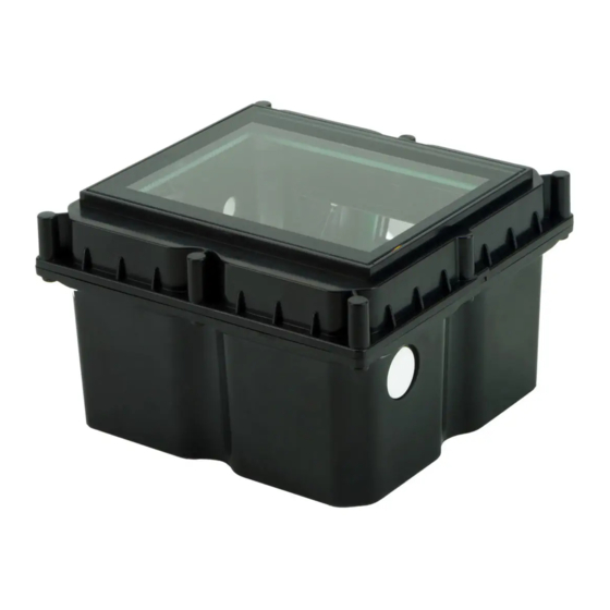
LSR118
1D/2D IP67 Barcode Imager
and NFC Reader
Product Manual
Advertisement
Table of Contents

Related Manuals for Access IS LSR118


Summary of Contents for Access IS LSR118
- Page 1 Subject: LSR118 Manual Revision: 1.2 LSR118 Issue Date: 12/08/2020 1D/2D IP67 Barcode Imager and NFC Reader Product names mentioned herein are for Product Manual identification purposes only and may be trademarks and/or registered trademarks of their respective companies. © Copyright 2020...
- Page 2 Warnings This manual contains important information regarding the installation and operation of the LSR118 1D/2D Barcode Imager and NFC reader. For safe and reliable operation of the imager, installers must ensure that they are familiar with, and fully understand, all instructions contained herein.
-
Page 3: Table Of Contents
Contents Overview ..........................6 Specifications ........................7 Part numbers ......................8 Installation .......................... 9 Unpack the LSR118 ....................9 Connection ........................ 9 Mounting ......................... 10 Barcode interface options ..................10 NFC interface options ....................11 Barcode module installation (serial device) .............. 12 Barcode module installation (USB device) ............... - Page 4 MIFARE media commands and responses ..............39 MIFARE get media type ..................39 MIFARE load key ....................40 MIFARE authenticate block (key A or key B) ............41 MIFARE read block (key A or key B) ............... 42 MIFARE write block (key A or key B) ............... 43 MIFARE create value block (key A or key B) ............
- Page 5 Disconnect the card ....................72 ASCII character reference ....................73 Document history ......................77 Page 5 of 77 Copyright © Access-IS 2020...
-
Page 6: Overview
1. Overview The Access-IS LSR118 is a compact 1D/2D barcode imager with near field communication (NFC) contactless capabilities. The device is purpose-designed for use in kiosk and gate applications and its rugged, water- resistant construction, with no moving parts, enables it to withstand years of indoor and outdoor public access use. -
Page 7: Specifications
2. Specifications Specification Details Dimensions (L x H x W) 109.8 mm x 67.4 mm x 105.9 mm Weight 592 g (with cable) Environmental Operating temperature: -25ºC to 50ºC Storage temperature: -30ºC to 70ºC Humidity: 95% RH, non-condensing IP67 Body Black ABS Glass 4 mm Toughened White Soda Lime;... -
Page 8: Part Numbers
2.1 Part numbers Product Part Number Serial connected LSR118 AKEGEOSA941 USB power injector cable 5KBD133402 USB connected LSR118 AKEGEOSA902 Serial cable 5KBD387302 USB cable 5KBD386301 An external power supply is available, if required. Please contact the Access-IS sales team: sales@access-is.com. -
Page 9: Installation
Report any missing items or damage immediately to your Sales Representative. 3.2 Connection Connect the LSR118 directly to two RS232 ports or a USB port depending on the product version. Note: The cable is sealed into the unit to prevent entry of water, moisture and dust. Cable length is 2 m for serial and USB versions. -
Page 10: Mounting
3.3 Mounting Mount the LSR118 into a kiosk, gate or similar device, if required. Refer to Figure 4 for the LSR118’s dimensions (in millimetres) and mounting points. For optimum performance, do not position the LSR118 in direct sunlight. NFC INSTALLATION WARNING To optimise the performance, DO NOT install the LSR118 so that its NFC antenna is within 40 mm of a large metal or electrically conductive component or structure. -
Page 11: Nfc Interface Options
3.4.2.1 Keyboard interface Virtual keyboard using Windows or Linux drivers This option allows the device to operate without additional drivers, with the LSR118 emulating a keyboard. This is one-way communication; it is not possible to control the device directly in this mode. -
Page 12: Barcode Module Installation (Serial Device)
Note: If you intend to use the Access driver, ensure that you install the driver before you connect the LSR118 to the computer. 3.7.1 Driverless keyboard output There is no additional driver required for this mode. Connect the USB cable from the LSR118 to a USB port on the computer. 3.7.2 CDC Windows driver This method of USB installation uses the Windows CDC drivers. -
Page 13: Nfc Module Installation (Usb Device)
Smartcard Resource Manager API. Refer to the Microsoft website for more detailed information on the Smartcard Resource Manager API. For more information on the operation of the LSR118’s NFC reader, see page 31. Refer to page 39 for MIFARE media commands and responses and page 56 for NFC management interface commands. -
Page 14: Troubleshooting
3.13 Troubleshooting If the LSR118 does not appear to be working, refer to Table 1 to help identify and resolve the problem. For further assistance, contact support@access-is.com. Alternatively, use the Contact Customer Support Team page on the Access-IS website. Note: Do not attempt to disassemble the LSR118 if it does not operate correctly. -
Page 15: Barcode Operating Modes
The LSR118 is a two-way communication device, controlled fully by a host. The LSR118 detects the media and sends a command to the host with this information. If the media is removed, a second command is sent telling the host that the media is no longer detected. -
Page 16: Dumb Mode
4.2 Dumb mode Figure 6 shows the process for a LSR118 in Dumb mode. Reader Idle Media Detected Imager and Illumination Activated Lights ‘Good Read’ (as Settings Barcode Read Instruct) Data Sent to Host Imager and Illumination Deactivated Reader Idle Figure 6. -
Page 17: Host Mode
4.3 Host mode Figure 7 shows the process for an LSR118 in Host mode. Reader Idle Media Detected Imager and Illumination Activated Barcode Read Data Sent to Host. Imager and Illumination Deactivated Accept or Reject? Reject Accept Ignore Command or No Response within Timeout Lights ‘Bad Read’... - Page 18 Host decides to accept or AISXXR0 reject the data. Lights activated as defined in the ‘Good Read’ settings. No media detected for 0.5 seconds; LSR118 resets. 4.3.1.2 Reject Comments LSR Command to Host Host Command to LSR Media placed in front of LSR118.
-
Page 19: Interactive Mode
4.4 Interactive mode Figure 8 shows the process for an LSR118 in Interactive mode. The host can send ‘Good Read’ and ‘Bad Read’ commands to the LSR118 at any time. Reader Idle Media Detected, Message Sent Untrigger Requesting Trigger Send Trigger? - Page 20 4.4.1.1 ‘Good Read’ initiated by LSR detecting media Comments LSR Command to Host Host Command to LSR [0x16][0x0D]TRIG:1[0x16][0x0A] Media placed in front of LSR118. LSR118 sends commands to host notifying of media. [0x16][0x74][0x0D] Host sends a command to trigger the imager.
-
Page 21: Barcode Command Reference
To query the current settings (including a temporary one) Send the six character command with a ‘?’ instead of the parameter and the LSR118 will return the command with the current setting. Note the ‘?’ must be followed with ‘.’... -
Page 22: Basic Configuration
5.1 Basic configuration These commands set the device interface, connection parameters and specify the operating mode. Table 2. Basic configuration commands Command Description Default Parameters/Range AISINF Selects the device interface. 0 - Serial When a Serial cable is used, the 1 - USB serial (CDC) AISINF0 configuration is overruled and... -
Page 23: Prefix And Suffix Solutions
Command Description Default Parameters/Range DLYGRD Sets the delay between successful 2000 0–25000 reading of one barcode and the reading of another barcode. Each unit is equivalent to 1 millisecond. 5.2 Prefix and suffix solutions These commands allow you to add a prefix and/or suffix to all barcodes. Note: If you send more than one prefix or suffix to the device, they will stack in chronological order. -
Page 24: Lsr118 Illumination
5.3 LSR118 illumination The standard method of reading barcodes cycles the illumination on and off. You can control illumination for various different applications using the commands in Table 4. For example, it is often beneficial to turn off the illumination to prevent reflections from shiny surfaces, for example, mobile phones. - Page 25 Command Description Default Parameters/Range AISOF1 Illumination off time 1. 0–200 AISILL Applies to modes 2 and 3 only (adaptive illumination on). Each unit is equivalent to 100 milliseconds. AISOF2 Illumination off time 2. 0–200 AISILL Applies to modes 2 and 3 only (adaptive illumination on).
-
Page 26: Indicator Control
5.4 Indicator control These commands control the behaviour of the ‘Good Read’ and ‘Bad Read’ LEDs. Note: There are no lid lights on the LSR118; these are replaced by the NFC antenna. Table 5. Indicator LED commands Command Description Default... -
Page 27: Development Commands
The firmware levels identify the release and build of a unit. Send the command to obtain this information. For example: SB 01.00.00 is a first generation LSR118. To check the latest firmware version or to update firmware, contact support@access-is.com. Table 6. Firmware and imager commands... - Page 28 5.5.2 Status LED The LSR118 contains two small orange LEDs on the main circuit board, typically used for debug purposes only. We recommend turning these off in normal use. A typical configuration will have these turned off, but the default values will be as below (for...
-
Page 29: Triggering
5.6.1 Interactive mode The commands to trigger the LSR118 for Interactive mode do not follow the same format as [0x16][0x74][0x0D] described in Table 8. For Interactive mode, trigger commands are sent as... -
Page 30: Counter
5.7 Counter These commands display the number of ‘Good’ or ‘Bad’ reads made by the device. Table 10. Counter commands Command Description Default Parameters/Range AISGRC ‘Good Read’ counter. Cannot be reset. AISBRC ‘Bad Read’ counter. Cannot be reset. Page 30 of 77 Copyright ©... -
Page 31: Nfc Operation
Once communication is complete, or a user removes the card, the NFC module disconnects from the card and waits for another card connection. Figure 9 shows an overview of the process that the NFC module in the LSR118 uses to identify and communicate with contactless media. - Page 32 Figure 9.NFC module-contactless media process flow Page 32 of 77 Copyright © Access-IS 2020...
-
Page 33: Serial Communication
6.2 Serial communication 6.2.1 Communication parameters The NFC module in a serial-connected LSR118 uses the following default serial communication settings. Change the serial device baud rate using the Set serial interface baud rate command (on page 65). Table 11. Serial communication default parameters... -
Page 34: Notifications And Data Exchanges (Serial Connection)
CCID Packet (256 bytes) 64 byte chunk 64 byte chunk 64 byte chunk 64 byte chunk At least 2 character At least 3 ms idle time for EOP idle time (~200µs) Figure 10. Example data transfer of a 256-byte data packet The entire CCID packet including the header is broken down into 64-byte packets, which are transmitted one at a time. - Page 35 Media type The value of the media type byte indicates the media type. Table 14. Media type byte values Media type value Type Current support [0x00] No Media present [0x01] ISO14443-4 A [0x02] ISO14443-4 B [0x03] Mifare Classic 1K [0x04] Mifare Classic 4K [0x05] Mifare Ultralight...
- Page 36 6.3.3 Get the ATR of the media Once media has been detected, the ATR of the media can be retrieved by sending the message, PC_to_RDR_IccPowerOn. This message is sent from the serial host as shown in Table 16. Table 16. PC_to_RDR_IccPowerOn message format Field Offset Size in bytes...
-
Page 37: Mifare Cards
Field Offset Size in bytes Value/Description abData Size of the data Contains the data to be sent to the media to be sent to the media abData The NFC module sends out the data in the field to the media. The media processes the data and replies with an appropriate response. -
Page 38: Contactless Microprocessor Smartcards
6.5 Contactless microprocessor smartcards The NFC module detects contactless microprocessor smartcards such as Java cards, ACOS, Desfire, SmartMX cards and most e-Passports. These media have an Answer to Reset (ATR), which the NFC module retrieves. The host application can send Application Protocol Data Unit (APDU) commands to these media using the Windows Smartcard API. -
Page 39: Mifare Media Commands And Responses
7. MIFARE media commands and responses This section describes the MIFARE media commands and responses for the NFC module. PC_to_RDR_XferBlock In serial mode, all MIFARE commands use a CCID message to communicate with the module/card. The application software should be aware of this and it should add/remove the CCID header from the command/responses. -
Page 40: Mifare Load Key
7.1.2 MIFARE response bytes MIFARE response bytes Response header Response code(1) MIFARE type (2) Media UID (2) Status bytes [0x00] [0x03] [0x90][0x00] Any one of the 4 bytes for following values cascade level 1 MIFARE Classic Success [0x01] [0x69][Status 7 bytes for [0x41] [0x04] Code]... -
Page 41: Mifare Authenticate Block (Key A Or Key B)
7.2.2 MIFARE response bytes MIFARE response bytes Response header Response code Status bytes [0x00] [0x90][0x00] Any one of the following values (Command code + 1) Success [0x03] [0x43] [0x69][Status Code] [0x83] [0xC3] Failure Refer to page 55 for information on MIFARE failure status codes. 7.2.3 Example This command successfully loads the 6-byte key into the NFC module for MIFARE authentication. -
Page 42: Mifare Read Block (Key A Or Key B)
7.3.2 MIFARE response bytes MIFARE response bytes Response header Response code Block number Status bytes [0x00] [0x90][0x00] Any one of the following Block number values (Command code + 1) Success [0x05] [0x45] [0x69][Status Code] [0x15] [0x55] Failure [0x85] [0xC5] [0x95] [0xD5] Refer to page 55 for information on MIFARE failure status codes. -
Page 43: Mifare Write Block (Key A Or Key B)
MIFARE command bytes Command header Command code Block number [0x86] [0xC6] RF select, authenticate and read block (Key A) [0x96] [0xD6] RF select, authenticate and read block (Key B) 7.4.2 MIFARE response bytes MIFARE response bytes Response header Response code Block number Block data (1) Status bytes... - Page 44 7.5.1 MIFARE command bytes MIFARE command bytes Command header Command code Block number Block data [0x00] [0x08] Block number 16 bytes Write block (Key A) [0x18] Write block (Key B) [0x48] Authenticate and write block (Key A) [0x58] Authenticate and write block (Key B) [0x88] [0xC8] RF select, authenticate and write block (Key A)
-
Page 45: Mifare Create Value Block (Key A Or Key B)
7.6 MIFARE create value block (key A or key B) Use this command to authenticate the specified MIFARE block against the MIFARE media’s internal Key A or B and then create a value block in that block number. The value block is initialised to the specified 32-bit initial value. -
Page 46: Mifare Increment Value Block (Key A Or Key B)
7.6.3 Example This command successfully creates a value field in block number 4 and initialises the value to [0x00000001]. The command uses the loaded key and authenticates against Key A in the media. [0x00][0x4A][0x04][0x00][0x00][0x0][0x01] Command: [0x00][0x4B][0x04][0x90][0x00] Response: Serial [0x6F][0x07][0x00][0x00][0x00][0x00][0x00][0x00][0x00][0x00] Command: [0x00][0x4A][0x04][0x00][0x00][0x00][0x01] [0x80][0x05][0x00][0x00][0x00][0x00][0x00][0x00][0x00][0x00] Response:... -
Page 47: Mifare Decrement Value Block (Key A Or Key B)
7.7.2 MIFARE response bytes MIFARE response bytes Response header Response code Block number Status bytes [0x00] [0x90][0x00] Any one of the following Block number values Success [0x69][Status Code] (Command code + 1) [0x0D] [0x1D] Failure [0x4D] [0x5D] [0x8D] [0xCD] [0x9D] [0xDD] Refer to page 55 for information on MIFARE failure status codes. - Page 48 MIFARE command bytes Command header Command code Block number Initial value [0x5E] Authenticate and decrement value block (Key B) [0x8E] [0xCE] RF select, authenticate and decrement value block (Key A) [0x9E] [0xDE] RF select, authenticate and decrement value block (Key B) 7.8.2 MIFARE response bytes MIFARE response bytes Response header...
-
Page 49: Mifare Ultralight Read Block
7.9 MIFARE Ultralight read block Use this command to read the contents of the specified block. The Ultralight card blocks are only 4 bytes long. Note: This command is applicable ONLY to MIFARE Ultralight cards and fails if executed on other MIFARE card types. -
Page 50: Mifare Ultralight Write Block
7.10 MIFARE Ultralight write block Use this command to write data to the specified block. Note: This command is applicable ONLY to MIFARE Ultralight cards and fails if executed on other MIFARE card types. 7.10.1 MIFARE Ultralight command bytes MIFARE Ultralight command bytes Command header Command code Block number... -
Page 51: Mifare Ultralight-C Authenticate - Part 1
7.11 MIFARE Ultralight-C authenticate - part 1 Use this command to perform the first part of the MIFARE Ultralight-C authentication. Note: This command is applicable ONLY to MIFARE Ultralight-C cards and fails if executed on other MIFARE card types. 7.11.1 MIFARE Ultralight-C command bytes MIFARE command bytes Command header Command code... -
Page 52: Mifare Ultralight-C Authenticate - Part 2
Serial [0x6F][0x02][0x00][0x00][0x00][0x00][0x00][0x00][0x00][0x00] Command: [0x00][0x24] [0x80][0x0E][0x00][0x00][0x00][0x00][0x00][0x00][0x00][0x00] Response: [0x00][0x25][0x00][0xAF][0x19][0xA0][0xC9][0xF4][0xC2][0x19] [0x16][0x2F][0x90][0x00] This command fails to authenticate with an error ‘MIFARE Ultralight-C Authentication Part 1 failed’. [0x00][0x24] Command: [0x00][0x25][0x00][0x69][0x8B] Response: Serial [0x6F][0x02][0x00][0x00][0x00][0x00][0x00][0x00][0x00][0x00] Command: [0x00][0x24] [0x80][0x05][0x00][0x00][0x00][0x00][0x00][0x00][0x00][0x00] Response: [0x00][0x25][0x00][0x69][0x8B] 7.12 MIFARE Ultralight-C authenticate - part 2 Use this command to perform the second part of the MIFARE Ultralight-C authentication. - Page 53 Note: Once the NFC module receives a command, it waits for 250 milliseconds for another command to arrive. If no command arrives, it resets the MIFARE card. This interval, the ‘Command Wait Time’, is configurable using the Set NFC timings command (on page 59). The NFC reader resets the MIFARE card after the ‘Command Wait Time’...
-
Page 54: Mifare Transceive Direct
7.13 MIFARE transceive direct Use this command to send commands directly to the MIFARE media. Warning: This is for advanced users only and provides low-level access to send and receive raw data. It is applicable to all MIFARE card types. Refer to the MIFARE card datasheet for data specifications. -
Page 55: Mifare Failure Status Codes
This command fails with an error ‘MIFARE direct transceive failed’. [0x00][0x28][0x00][0x30][0x00] Command: [0x00][0x29][0x00][0x69][0x8D] Response: Serial Command: [0x6F][0x05][0x00][0x00][0x00][0x00][0x00][0x00][0x00][0x00] [0x00][0x28][0x00][0x30][0x00] [0x80][0x05][0x00][0x00][0x00][0x00][0x00][0x00][0x00][0x00] Response: [0x00][0x29][0x00][0x69][0x8D] 7.14 MIFARE failure status codes The following table gives the status codes for MIFARE command failures. MIFARE failure code Failure description [0x80] Missing parameters... -
Page 56: Nfc Management Interface Commands
8. NFC management interface commands The NFC module exposes an interface, known as the Management Interface. Your application software uses to manage and configure the NFC module. This section of the manual describes the command set and its responses. Note: If there is a response to the command, the command is successful. If the command times out, it has failed. -
Page 57: Get Bootloader Version
8.1.3 Example This command retrieves the firmware version (0112). [0x00] Command: [0x00][0x01][0x12] Response: Serial [0x6F][0x01][0x00][0x00][0x00][0xFF][0x00][0x00][0x00][0x00] Command: [0x00] [0x80][0x36][0x00][0x00][0x00][0xFF][0x00][0x00][0x00][0x00] Response: [0x00][0x01][0x12] 8.2 Get bootloader version Use this command to retrieve the bootloader version on the NFC module. 8.2.1 Management command bytes Byte Command/Value Comments... -
Page 58: Switch To Bootloader
8.3 Switch to bootloader Use this command to switch to the bootloader to load new firmware. The module resets itself in bootloader mode soon after the sending the response. Warning: Only use this command when loading new firmware. Using this command at any other time may cause the device to become inoperable. -
Page 59: Set Nfc Timings
Use this command to set various operating timings for the NFC reader. This is an 11-byte command starting for the command byte. Warning: Access-IS optimise the NFC timings for the LSR118 and these values should not need to be changed. The NFC module does not modify a timing value if its value is set to zero (0) when you send the command. -
Page 60: Get Nfc Timings
Byte Command / Value Comments [0x05] RF reset time during MIFARE select Default - 5 milliseconds (LSB) [0x00] Media warm up time for MIFARE media Default - 0 milliseconds [0xFA] Command waiting time for MIFARE Default - 250 milliseconds media (MSB) [0x64] Command waiting time for MIFARE Default - 100 milliseconds... -
Page 61: Enter Sleep Mode
8.6.2 Management response bytes Byte Response/Value Comments [0x06] Command echoed [0x00] Same as command byte 1 [0x80] Same as command byte 2 [0x00] RF reset time for media polling (LSB) Default - 0 milliseconds [0x64] RF reset time for media polling (LSB) Default - 100 milliseconds [0x14] Media warm up time... -
Page 62: Exit Sleep Mode
8.7.2 Management response bytes Byte Response/Value Comments [0x07] Command echoed [0x90] - Success [0x90] [0x69] [0x69] - Failure [0x00] [0x00] 3–63 Ignored (61 bytes) 8.7.3 Example This command sets the device in sleep mode. [0x07] Command: [0x07][0x090][0x0] Response: Serial [0x6F][0x01][0x00][0x00][0x00][0xFF][0x00][0x00][0x00][0x00] Command: [0x07] [0x80][0x36][0x00][0x00][0x00][0xFF][0x00][0x00][0x00][0x00]... -
Page 63: Get Nfc Kernel Version
8.10 Get media serial number Use this command to get the media serial number. Table 20 shows the data element returned by the reader for different types of media. Table 20. Media types and data elements returned by the LSR118 Media type Data element... - Page 64 8.10.1 Management command bytes Byte Command/Value Comments [0x0D] Command byte [0x00] [0x00] 1–63 Unused bytes, set to 8.10.2 Management response bytes Byte Response/Value Comments [0x0D] Command echoed Media type value See Table 21 Number of valid bytes to follow Specifies the number of bytes in the serial number 3–xx Media serial number...
-
Page 65: Disable Media Arrival And Removal Notifications
Media type Type value Current support [0x08] ISO15693 [0x09] NFC Type 1 Tag [0x0A] NFC DEP media 8.11 Disable media arrival and removal notifications Use this command to disable the media arrival/removal notifications sent from the NFC module; the NFC module becomes a slave unit. The application software should poll for the card by sending the Get media serial number command (on page 63). - Page 66 Byte Command/Value Comments [0x10] Command byte [0x00] - > 9600 Kbps Sets the required baud rate [0x01] - > 19200 Kbps [0x02] - > 38400 Kbps [0x03] - > 57600 Kbps [0x04] - > 115200 Kbps (Default) [0x05] - > 153600 Kbps [0x06] - >...
-
Page 67: Nfc Module Serial Number Matching
A. NFC module serial number matching The NFC module in the LSR118 exposes a maximum of five CCID smartcard readers and one HID interface for management. It may be possible that a system is connected to two or more modules. In this scenario, the application software should perform serial number matching to determine which readers are physically present together in one module. -
Page 68: Hid Reports - Barcode Only
B. HID reports – barcode only B.1 Receive data Data received from the LSR118 will be in a HID input report, structured as below: Byte Report ID = 2 Length of data field AIM symbology Identifier (always ‘]’) AIM symbology Identifier 1... -
Page 69: Send Commands
[0x20]100 [0x00] [0x00] [0x00] [0x00] [0x73] - ‘s’ [0x00] B.2 Send commands To send commands to the LSR118, use a HID out report with the following structure: Byte Report ID = 253 Data length Output data (up to 62 bytes) B.2.1 Example output report to request firmware version... -
Page 70: Trigger Controls
B.3 Trigger controls To set the device status to activate the ‘read’ lights on the device, send an HID output report with the following structure: Byte Report ID = 4 Activate Activate Initiate Prevent ‘Good ‘Bad barcode barcode Read’ Read’ read read light... -
Page 71: Nfc Module Example Code And Api Functions
C. NFC module example code and API functions This section presents code snippets for the NFC module process flow (see Figure 9 on page 32). The main API functions in are shown in red. C.1 Initialise smartcard sub-system // Try to establish the Smartcard sub-system context while(SCardEstablishContext(SCARD_SCOPE_SYSTEM, NULL, NULL, &hRFIDContext) != SCARD_S_SUCCESS) Sleep(1000);... -
Page 72: Get Atr Of The Card
C.4 Get ATR of the card RcvLength = 128; if(SCardStatus(hCrd, (LPSTR)_Buffer, &RcvLength, NULL, NULL, ATR, &_ATRLen) != SCARD_S_SUCCESS) SCardDisconnect(hCrd, SCARD_LEAVE_CARD); MessageBox(“Unable to get ATR of card”); else MessageBox(“ATR successful”); C.5 Communicate with card RcvLength = RX_BUFFER_SIZE; if(SCardTransmit(hCrd, &SendPci, TX_Buffer, Transmit_Length, NULL, RX_Buffer, &RcvLength) != SCARD_S_SUCCESS) MessageBox(“Communication failed”);... - Page 73 D. ASCII character reference Symbol Description Null char Start of heading Start of text End of text End of transmission Enquiry Acknowledgment Bell Back space Horizontal tab Line feed Vertical tab Form feed Carriage return Shift out / X-on Shift in / X-off Data line escape Device control 1 (oft.
- Page 74 Symbol Description & Ampersand Single quote Open parenthesis (or open bracket) Close parenthesis (or close bracket) Asterisk Plus Comma Hyphen Period, dot or full stop Slash or divide Zero Three Four Five Seven Eight Nine Colon Semicolon < Less than (or open angled bracket) Equals >...
- Page 75 Symbol Description Uppercase N Uppercase O Uppercase P Uppercase Q Uppercase R Uppercase S Uppercase T Uppercase U Uppercase V Uppercase W Uppercase X Uppercase Y Uppercase Z Opening bracket Backslash Closing bracket Caret - circumflex Underscore Grave accent Lowercase a Lowercase b Lowercase c Lowercase d...
- Page 76 Symbol Description Lowercase v Lowercase w Lowercase x Lowercase y Lowercase z Opening brace Vertical bar Closing brace Tilde Delete Page 76 of 77 Copyright © Access-IS 2020...
- Page 77 E. Document history Issue Date Description 15.03.2016 First issue. 30.10.2018 Updates to Approvals section. 12.08.2020 Added note to Command reference introduction about following commands with a ‘.’ Page 77 of 77 Copyright © Access-IS 2020...
Need help?
Do you have a question about the LSR118 and is the answer not in the manual?
Questions and answers