Table of Contents
Advertisement
Available languages
Available languages
TASMAN DV LINEAR FIREPLACE
21,000 BTU
Natural Gas
Installation and Operating Instructions
MODEL: BL21
IF THE INFORMATION IN THESE INSTRUCTIONS IS
NOT FOLLOWED EXACTLY, A FIRE OR EXPLOSION
MAY RESULT CAUSING PROPERTY DAMAGE,
PERSONAL INJURY, OR DEATH.
Do not store or use gasoline or other flammable
vapors and liquids in the vicinity of this or any other
WHAT TO DO IF YOU SMELL GAS:
Do not try to light any appliance
Do not touch any electrical switch; do not use
any phone in your building
Immediately call your gas supplier from a
neighbour s phone. Follow gas supplier s
instructions
If you cannot reach your gas supplier, call the
fire department.
Installation and service must be performed by a
qualified installer, service agency or gas
supplier.
WARNING: Improper installation, adjustment,
alteration, services or maintenance can cause injury
or property damage. Refer to this manual. For
assistance or additional information consult a
qualified installer, service agency or the gas
supplier.
PLEASE READ THIS MANUAL BEFORE INSTALLING OR USING THIS APPLIANCE.
CERT # LC773211
WARNING
appliance.
SAVE THIS MANUAL FOR FUTURE REFERENCE.
D
UE TO HIGH TEMPERATURES
THE APPLIANCE SHOULD BE
LOCATED OUT OF TRAFFIC AND
AWAY FROM FURNITURE AND
DRAPERIES
C
HILDREN AND ADULTS SHOULD
BE ALERTED TO THE HAZARDS
OF HIGH SURFACE
TEMPERATURE AND SHOULD
STAY AWAY TO AVOID BURNS OR
CLOTHING IGNITION
Y
OUNG CHILDREN SHOULD BE
SUPERVISED WHEN THEY ARE IN
THE SAME ROOM AS THE
APPLIANCE
C
LOTHING OR OTHER
FLAMMABLE MATERIAL SHOULD
NOT BE PLACED ON OR NEAR THE
APPLIANCE
KEEP THE ROOM AREA CLEAR AND
FREE FROM COMBUSTIBLE
,
MATERIALS
GASOLINE
OTHER FLAMMABLE VAPORS AND
.
LIQUIDS
,
.
.
.
.
,
AND
Page 1 of 60
Advertisement
Table of Contents

Related Manuals for Savannah BL21


Summary of Contents for Savannah BL21
-
Page 1: Natural Gas
TASMAN DV LINEAR FIREPLACE 21,000 BTU Natural Gas Installation and Operating Instructions MODEL: BL21 CERT # LC773211 UE TO HIGH TEMPERATURES WARNING THE APPLIANCE SHOULD BE IF THE INFORMATION IN THESE INSTRUCTIONS IS LOCATED OUT OF TRAFFIC AND NOT FOLLOWED EXACTLY, A FIRE OR EXPLOSION... - Page 2 DV TASMAN FOYER LINEAR AU GAZ NATUREL Manuel D installation et Guide de l utilisateur CERT # LC773211 N RAISON DE TEMPERATURES AVERTISSEMENT ELEVEES APPAREIL DOIT ETRE ASSUREZ-VOUS DE BIEN SUIVRE LES INSTRUCTIONS PLACE HORS DE LA CIRCULATION DONNÉES DANS CETTE NOTICE POUR RÉDUIRE AU ET LOIN DES MEUBLES ET MINIMUM LE RISQUE D'INCENDIE OU D'EXPLOSION OU TENTURES...
-
Page 3: Table Of Contents
Table of Contents IMPORTANT SAFETY INFORMATION .. 4 INTRODUCTION ........................Specifications, Appliance Dimensions & Installation Codes........6 - 7 Features, Remote Control Functions ..............8 - 10 Intended Use ......................11 General Safety....................11 - 12 OPERATION .......................... Lighting Instructions ..................13 Heat Output adjustment Fan Operation 17 - 18... -
Page 4: Important Safety Information
INSTALLER: Leave this manual with the INSTALLATEUR : Laissez cette notice avec appliance. l appareil. CONSUMER: Retain this manual for future CONSOMMATEUR : Conservez cette notice reference. pour consultation ultérieure. WARNING Read this owner s manual carefully and completely before trying to assemble, operate or service this fireplace. - Page 5 WARNING AVERTISSEMENT Do not use this appliance if any part has Ne pas utiliser cet appareil s il a été plongé, been under water. Immediately call a meme partiellement, dans l eau. Appeler un qualified service technician to inspect the technician qualifié...
-
Page 6: Introduction
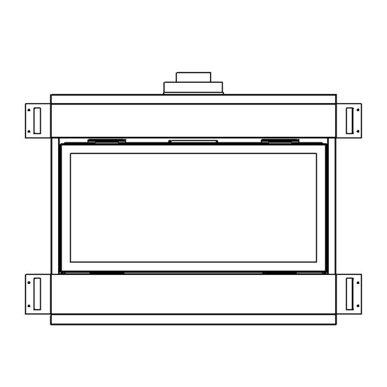
1.0 INTRODUCTION 1.1 SPECIFICATIONS TABLE 1 ITEM NATURAL GAS (NG) INPUT: Hi 21,000 Btu/hr (6.15 kW) INPUT: Lo 13,000 Btu/hr (3.81 kW) MANIFOLD PRESSURE: Hi 3.5 w.c. (0.87 kPa) COLLECTEUR DE PRESSION: FORT MANIFOLD PRESSURE: Lo 1.7 w.c. (0.42 kPa) COLLECTEUR DE PRESSION: FAIBLE GAS INLET SUPPLY PRESSURE: Minimum: 5.0 w.c. - Page 7 APPLIANCE DIMENSIONS Figure 1 34.133 17.134 15.50 8.872 16.000 29.565 1.500 27.503 13.040 7.400 38.000 14.416 INSTALLATION CODES This appliance is a Direct Vent appliance which draws all combustion air from outside the building through an intake vent pipe. Installation must conform to local codes. In the absence of local codes, installation must conform to the National Fuel Gas Code ANSI Z223.1/NFPA 54, or the current Natural Gas and Propane Installation Code B149.1.
-
Page 8: Features, Remote Control Functions
1.2 FEATURES Ignition system: Standing pilot ignition system with thermopile and thermocouple flame detection and piezo igniter. Fan control * Optional * Variable speed control: For units equipped with a fan control, the knob controls the fan speed, turning the knob counter-clockwise turns it to the Off position. - Page 9 Program Mode The Program function is controlled by the PROG/TIME button. The control may be programmed for up to two settings for weekdays and two settings for weekends. The control is preset to factory settings. When the Program Mode is activated, the unit will automatically be operating in the Thermostat Mode. The unit will turn on or off based upon room and set temperature.
- Page 10 Fan Control The unit must be ON to operate the Fan. The Fan will turn on after 5 minutes of operation. Once the Fan comes on, it can be controlled using the FAN button. Press the FAN button, and the fan icon and speed will appear on the LCD screen. Press the UP or DOWN button to control the fan speed (0-6).
-
Page 11: Intended Use
1.3 INTENDED USE / USAGE PROPOSÉ This appliance is intended to be used as a zero clearance fireplace. This unit is certified for installation in a bedroom or a bed sitting room where the maximum input is within 50 cubic feet per 1000 Btu/hr, (i.e. 900 cubic feet for E unit & 1600 cubic feet for H unit). - Page 12 IMPORTANT PLEASE READ THE FOLLOWING CAREFULLY It is normal for fireplaces fabricated of steel to give off some expansion and/or contraction noises during the start up or cool down cycle. It is not unusual for gas fireplaces to give off some odors the first time they are burned. This is due to the oils and sealants in the manufacturing process.
-
Page 13: Operation
2.0 OPERATION LIGHTING INSTRUCTIONS - for Intermittent Pilot FOR YOUR SAFETY, READ BEFORE LIGHTING WARNING: If you do not follow these instructions exactly, a fire or explosion may result causing property damage, personal injury or loss of life. This appliance is equipped with an ignition device which automatically lights the pilot. Do not try to light the pilot by hand. BEFORE LIGHTING smell all around the appliance area for gas. - Page 14 INSTRUCTIONS D'ALLUMAGE - Pilote intermittent POUR PLUS DE SÉCURITÉ, LIRE AVANT D ALLUMER AVERTISSEMENT: Quiconque ne respecte pas à la letter les instructions dans la présente notice risqué de déclencher un incendie ou une explosion entraînant des dommages, des blessures ou la mort. Cet appareil est équipé...
- Page 15 2.1 LIGHTING INSTRUCTIONS FOR YOUR SAFETY, READ BEFORE LIGHTING WARNING: If you do not follow these instructions exactly, a fire or explosion may result causing property damage, personal injury or loss of life. This appliance has a pilot which must be lighted by hand. When lighting the pilot, follow these instructions exactly. BEFORE LIGHTING smell all around the appliance area for gas.
- Page 16 2.1 INSTRUCTIONS D'ALLUMAGE POUR VOTRE SÉCURITÉ, LIRE AVANT D'ALLUMER ATTENTION: Si vous ne suivez pas exactement ces instructions, un incendie ou une explosion entraînant des dommages matériels, des blessures ou des pertes de vie. Cet appareil a un pilote qui doit être allumée à la main. Lorsque l'éclairage, le pilote, suivez ces instructions à la lettre. AVANT L'ALLUMAGE odeur tout autour de l'appareil pour le gaz.
-
Page 17: Heat Output Adjustment
Robertshaw 9A0A68A6A 2.2 HEAT OUTPUT ADJUSTMENT The valve supplied with the appliance has a HI/LO knob to control the heat output and flame height (see valve diagram in Lighting Instructions, section 2.1). 2.3 FAN OPERATION For units equipped with a fan control knob, the knob is located in the valve control compartment and may be adjusted to the following settings: OFF: Turn the control fully counter-clockwise until the switch operates. - Page 18 Figure 2 Page 18 of 60...
-
Page 19: Installation
3.0 INSTALLATION 3.1 INSTALLATION & SAFETY NOTES / NOTES D'INSTALLATION ET DE SECURITE Read all instructions before starting installation and follow them carefully during installation to ensure maximum benefit and safety. Failure to follow these instructions will void your warranty and may present a fire hazard. -
Page 20: Minimum Clearances To Combustibles
3.3.1 MINIMUM CLEARANCES / DÉGAGEMENTS 36.000 48.000 447.00 33.500 0.000 38.000 Framing Dimensions 38 wide x 34.5 high x 15.5 deep 2.000 2.000 15.500 6.000 MINIMUM CLEARANCES TO COMBUSTIBLES A = 48 TO INTERNAL CEILING B = 2 TO INTERNAL SIDE COMBUSTIBLES C = 15.5 TO BACK WALL FROM FRONT OF UNIT D = 6... - Page 21 Mantle 40.000 12.000 Clearances are in accordance with local installation codes and the requirements of the gas supplier. **The mantel placement chart on this page illustrates the allowable mantel sizes and placements. The 45 degree angle can be used to determine the allowable mantel size based on the elevation above the units upper trim.
- Page 22 Heat Baffle fixed to Non-combustible non-combustible board board supplied by by manufacturer (see manufacturer diagram next page for side view) 15.500 8.052 33.500 34.500 26.355 36.000 38.000 NOTE STUD MUST BE INSTALLED ON EDGE AS SHOWN IN THIS DIAGRAM The closest combustible material above the fireplace must be a minimum of 33.50 from the floor with the stud laying on edge as shown above.
-
Page 23: Gas Line Installation
NON COMBUSTIBLE MATERIAL/ MATIERE NON COMBUSTIBLES Non-combustible material will be supplied by the manufacturer. This must be installed on top of the fireplace as shown above to meet installation codes. Heat baffle will be installed to non-combustible board by manufacturer. Matériaux non combustibles seront fournis par le fabricant. - Page 24 Upon initial firing check manifold pressure at pressure tap located on the front control panel (see Lighting Instructions in section 2.1 ). Lors de la première vérification de la pression de tir collecteur à la pression du robinet situé sur le panneau de commande avant (voir les Consignes d'allumage à la section 2.1). WARNING AVERTISSEMENT DO NOT USE AN OPEN FLAME TO TEST FOR GAS LEAKS...
-
Page 25: Thermostat,Wall Switch Or Digital On/Off Remote
TABLE 1 THERMOSTAT WIRE INFORMATION WIRE SIZE MAX. WIRE LENGTH 12.2 19.5 30.5 After the unit is installed and the gas line hooked up, crimp a fork connector to each wire and attach them to the TH/TP and TH screws located on the valve. Après que l'unité... -
Page 26: Direct Vent Information
3.3.4 DIRECT VENT INFORMATION / DIRECT VENT D'INFORMATION The unit must be connected to listed 2-ply aluminium venting, 4 flex vent on the exhaust side and listed 7 flex vent on the air intake side or can be used with Security Venting or Simpson Dura-Vent 4 x 6-5/8 with the use of Simpson Dura-Vent adapters part # s 0924N3 &... - Page 27 Figure 6 Dura-Vent The minimum vent system for horizontal termination must consist of: Dura-Vent adapter Part # 0924N3 directly on top of unit 12 (305mm) vertical length of vent 90 degree elbow 12" (305 mm) length horizontally Wall thimble part #IMC1082A Horizontal termination cap 0984 The maximum horizontal vent system consists of: Dura-Vent adapter Part # 0924N3 directly on top of unit...
- Page 28 Dura-Vent adapter Part # 0924N3 directly on top of unit Up to 34' (10363 mm) of vertical length Fire stop Flashing Collar Termination cap part # SV4CGV Use a ceiling fire stop when penetrating a ceiling or floor. Use a wall thimble when penetrating an inside or outside wall.
- Page 29 VENT TABLE (All values are in feet) 1 & 2 2 ½ 5 ½ 4 ½ 8 ½ 7 ½ 11 ½ 11 ½ 11 ½ 11 ½ 11 ½ 11 ½ V = 34 Feet Max. = 11 ½ Feet Max NOTE: All vent dimensions are measured from the appliance surface where the vent connects to the point where exhaust gases exit the termination.
- Page 30 12 Minimum 24 Maximum (Example: Where A---A = Vertical @ 2 ½ B---B = Horizontal @ 5 ) Page 30 of 60...
- Page 31 USE OF SEALANT Sealant is required on vent system joints (figure 7). On longer vent runs, especially vertical runs, sealant will ensure that the combustion air enters from outdoors, and not through the vent joints. Use high temperature sealant, available from local suppliers, on the inner pipe joint, applying the sealant around the outside of the male part of the vent.
- Page 32 VENT RESTRICTOR INSTALLATION (continued) The restrictors are installed by removing the 2 screws on the ceiling of the firebox, place the desired restrictor in place and use the screws to fasten the restrictor to the firebox. You must first remove the firebox baffle (4 screws) before installing the desired restrictor.
- Page 33 48.000 Safety Cage 15.500 Mark a 11 x 11 square around the center mark (inside dimensions). Cut and frame the exterior wall to accept the wall thimble. Install the wall thimble, on the inside of the exterior wall, shield using wood screws. Attach the venting to the termination using sheet metal screws, for Z-Flex installations an Inca Metal Cutting s termination part # IMC1070A or IMC1070B shall be used and when using Simpson Dura-Vent or Security Venting a Simpson Dura-Vent termination part # P574 shall be used.
- Page 34 Vertical Installations Always maintain a 1 clearance around the vent pipe (vertical) and 1 clearance horizontal, when passing through ceilings, walls, roofs, enclosures, attic rafter or any combustible surfaces. DO NOT PACK AIR SPACES WITH INSULATION NE PAS PACK ESPACES D'AIR AVEC ISOLATION When passing through a flat ceiling install a Box/Wall thimble.
- Page 35 Termination above Roof Consult local codes for minimum vent cap height above the roof (X), vent must be a minimum of 2 from any wall. To prevent water seepage; install the flashing with upper portion under the roofing material and the lower portion over the roofing material.
- Page 36 In accordance with the current CSA B149.1, Natural Gas and Propane Installation Code In accordance with the current ANSI Z223.1 / NFPA 54, National Fuel Gas Code A vent shall not terminate directly above a sidewalk or paved driveway that is located between two single family dwellings and serves both dwellings Permitted only if veranda, porch, deck or...
-
Page 37: Glass Installation
3.3.5 Glass Installation / Installation de verre Burn medium positions are critical to the safe and clean operation of this appliance. Never add any other material into the firebox. Use only with burn medium supplied with this unit. Burn positions moyennes sont critiques pour le fonctionnement sûr et propre de cet appareil. -
Page 38: Door Installation
3.3.6 Door Installation Fit the top of the door onto the top door brackets, make sure the door is centered on the appliance. Push the bottom of the door into the appliance and pull the 2 door lock bars down, forward and up to secure the door in place. -
Page 39: Initial Firing
Do not operate this appliance with the glass front removed, cracked or broken. Replacement of the glass should be done by a licensed or qualified service person. For use with glass doors certified with the appliance only Do not use any substitute materials Do not abuse glass doors by striking or slamming shut Ne pas faire fonctionner cet appareil avec la façade en verre est enlevée, fissurée ou cassée. -
Page 40: Primary Air Adjustment
PILOT FLAME ADJUSTMENT For proper operation, the pilot and main burner flames must be steady and not lifting off or floating. The top 3/8 1/2 (10-13mm) of the thermocouple should be engulfed by the pilot flame. 3.3.9 PRIMARY AIR ADJUSTMENT / AJUSTEMENT DE L'AIR PRIMAIRE Aeration is factory set but may need adjustment for altitude or movement during shipping. -
Page 41: Altitude Adjustment
Aeration adjustment is important for the correct functioning of the appliance. Carbon build up, flame lifting or any malfunction due to improper aeration adjustment during installation is not covered under the factory warranty. Réglage de l'aération est importante pour le fonctionnement correct de l'appareil. Une accumulation de carbone, de levage flammes ou de toute défaillance due à... - Page 42 Optional Rock Kit shown 3/. Remove the access panel in the middle of the firebox just in front of the burner / Retirez le panneau d'accès au milieu du foyer, juste en face du brûleur 4/. The fan is attached with magnets for ease of installation and can be pulled off the rear wall. / Les fan sont attachés avec des aimants pour la facilité...
- Page 43 5/. Once removed from the wall the fan will slide out through the opening. / Une fois retiré du mur que les fan vont glisser par l'ouverture. 6/. To replace fan and reassemble the fireplace go in reverse order from steps 5 through 1. / Pour remplacer les fan et montons la cheminée aller dans l'ordre inverse des étapes 5 à...
-
Page 44: Gas Valve Access
3.3.12 GAS VALVE ACCESSIBILITY / ACCESSIBILITÉ ROBINET DE GAZ. TURN THE MAIN GAS & POWER OFF TO FIREPLACE BEFORE COMMENCING ANY WORK ON THE FIREPLACE THIS SHOULD BE DONE BY A LICENSED, CERTIFIED GAS INSTALLER TURN LE PRINCIPAL GAZ ET MISE HORS TENSION AU FOYER AVANT DE COMMENCER TOUT TRAVAIL SUR LA FOYER CELA DEVRAIT ETRE FAIT PAR UNE LICENCE, VOTRE FOURNISSEUR DE GAZ 1/. -
Page 45: Maintenance
4.0 MAINTENANCE 4.1 MAINTENANCE SAFETY WARNING AVERTISSEMENT TURN OFF THE GAS TO THE MAIN BURNER AND ALLOW THE HEATER TO COOL FOR UP TO 30 MINUTES BEFORE SERVICING. COUPEZ LE GAZ AU BRÛLEUR PRINCIPAL ET LAISSEZ L'APPAREIL REFROIDIR PENDANT JUSQU'À 30 MINUTES AVANT L'ENTRETIEN. Service and repair should be done by a qualified service person. -
Page 46: Valve & Pilot Replacement
4.5 VALVE AND PILOT ASSEMBLY REPLACEMENT WARNING AVERTISSEMENT THE FOLLOWING PROCEDURE IS TO BE PERFORMED BY QUALIFIED PERSONNEL ONLY TURN OFF THE GAS TO THE MAIN BURNER AND ALLOW THE HEATER TO COOL FOR UP TO 30 MINUTES BEFORE SERVICING. LA PROCÉDURE SUIVANTE EST EFFECTUER PAR DU PERSONNEL QUALIFIÉ... -
Page 47: Trouble Shooting
5.0 TROUBLE SHOOTING SYMPTOM CORRECTIVE ACTION POSSIBLE CAUSE Pilot will not light after A. No spark at electrode (weak or not heat source for pilot ignition) repeated triggering of the piezo ignition button 1. Improper ignition 1. Align the electrode with 1/8 (3mm) gap to pilot hood 2. - Page 48 III. Main burner will not light A. Valve / Switches 1. Valve control off 1. Turn to ON position 2. Blockage at the burner (line, 2. Check and clean orifice, or ports) 3. Defective wall switch 3. Conduct a continuity test or jumper wire thermostat test and replace if defective 4.
- Page 49 TROUBLE SHOOTING - INTERMITTENT PILOT SYMPTOM CORRECTIVE ACTION POSSIBLE CAUSE A. No spark at electrode (weak or not heat source for pilot ignition) I. Pilot will not light after repeated triggering of the remote control intermittent pilot 1. Improper ignition 1.
- Page 50 4. Defective wiring or connections 4. Conduct a test with a jumper wire and repair as required 5. Defective Valve 5. Contact service technician III. Soot deposits 1. Air inlet blocked or restricted Clean air inlets 2. Vent system is restricted or 2.
-
Page 51: Replacement Parts
6.0 REPLACEMENT PARTS When requesting service or replacement parts for your unit, please provide model name and serial number. All parts listed below may be ordered from an authorized dealer. Description Part# Door IMC512 Burner IMC514 IMC542 Door Glass IMC528 Restrictor IMC524 Door Glass Gasket... -
Page 52: Warranty
7.0 INCA METAL CUTTING S WARRANTY PROTECTION FOR ALL INCA METAL CUTTING GAS FIREPLACE PRODUCTS Inca Metal Cutting s products are designed with superior components and materials, assembled by trained craftsmen who take great pride in their work. The burner and valve assembly are leak tested and test fired at a quality control test station. - Page 53 CONDITIONS AND LIMITATIONS (continued) Notwithstanding any provisions contained in this warranty, Inca Metal Cutting s responsibility under this warranty is defined as above and it shall not in any event extend to any incidental, consequential or indirect damages. This warranty defines the obligations and liability of Inca Metal Cutting with respect to the Inca Metal Cutting gas fireplace and any other warranties expressed or implied with respect to this product, its components or accessories are excluded.
- Page 54 CONDITIONS ET LIMITES (SUITE) doit être faite en conformité avec les instructions d'installation incluses avec le produit et toutes les capacités locales et nationales et de prévention des incend Cette garantie limitée ne couvre pas les dommages causés par une mauvaise utilisation, manque d'entretien, accident, des altérations, des abus ou de négligence.
-
Page 55: Label Information
8.0 LABEL INFORMATION Page 55 of 60... - Page 56 8.0 LABEL INFORMATION (continued) Sections of the venting system have not been installed. WARNING Do not operate the appliance until all sections have been assembled and installed in accordance with the manufacturer s instructions. Des sections du système d évacuation n ont pas été installées. AVERTISSEMENT - Ne pas utiliser l appareil tant que toutes les sections n ont pas été...
-
Page 57: Appendix A (Intermittent Pilot & Valve Kit)
APPENDIX A (AMERICAN FLAME VALVE INFORMATION) Page 57 of 60... - Page 58 APPENDIX A (Continued) Page 58 of 60...
- Page 59 APPENDIX A (Continued) Special Features on the AF-4000 System The AF-4000 Module can be powered two different ways. The first is a standard 110 volt AC to 6.0 volt DC adaptor. This adapter is connected to the AF-4000 Module by connecting the two 1/4 female terminals from the adapter to the two 1/4 male terminals, located on the AF-4000 Module , marked POWER.
- Page 60 APPENDIX A (Continued) AF-4000 Wiring Diagram Inca Metal Cutting Unit 100 11091 Bridgeport Road Richmond, BC V6X 1T3 Canada Page 60 of 60...
Need help?
Do you have a question about the BL21 and is the answer not in the manual?
Questions and answers