Table of Contents
Advertisement
Quick Links
Look Inside for:
Specifications
Safety Definitions
Important Safety Information
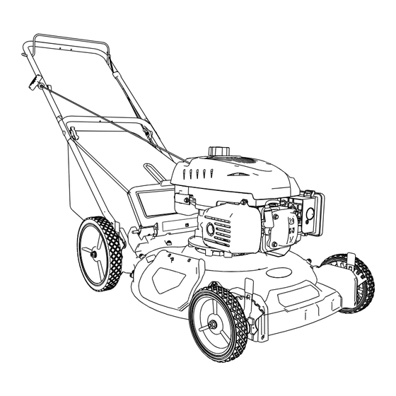
Parts & Features
Assembly
Operation
Maintenance
Storage
Technical Service
Troubleshooting
Warranty
Repair Parts
IMPORTANT:
This manual provides complete instructions for safely operating and maintaining your mower.
Read and save these instructions. Refer to this manual each time before using your mower.
Record the following for future reference:
Model No: ___________________
Mfg. Date Code: _________________________________________
Date of Purchase: Attach a copy of your sales receipt.
Consumer Toll Free Number: 1-800-737-2112
Refer to the website for electronic manual and parts book.
If you have a question or problem...
CALL TOLL FREE: 1-800-737-2112
KEEP THIS MANUAL FOR FUTURE REFERENCE
09/10/2014
Operator's Manual
WALK-BEHIND
LAWN MOWER
Page
4-6
9-10
11-15
16-18
21-23
24-26
www.southlandpowerequipment.com
Printed in the USA
2
3
8
19
19
20
MODEL NO
SM2243
A203007
Advertisement
Table of Contents

Related Manuals for Southland SM2243


Summary of Contents for Southland SM2243
-
Page 1: Lawn Mower
Operator’s Manual MODEL NO WALK-BEHIND SM2243 LAWN MOWER Look Inside for: Page Specifications Safety Definitions Important Safety Information Parts & Features Assembly 9-10 Operation 11-15 Maintenance 16-18 Storage Technical Service Troubleshooting Warranty 21-23 Repair Parts 24-26 IMPORTANT: This manual provides complete instructions for safely operating and maintaining your mower. -
Page 2: Specifications
Specifications MODEL SM2243 Cutting Width 21.61 in (549 mm) 1-1/8˝ to 3-3/4˝ (28.8-96.6 mm) Cutting Depths 3-position height adjust Blade Bolt Torque 25-30 ft/lbs Unit Weight 60 lb (27.2 kg) Gasoline Type Regular Unleaded, >=87 Octane Fuel containing Ethanol > 10% is not recom- mended.•... -
Page 3: Safety Definitions
Safety Definitions • Save all instructions Safety Warning Symbols Become familiar with and understand the meaning of the warning symbols found on your mower. Indicates WARNING, DANGER, or CAUTION. Do not mow when children Use common sense. Watch or others are around. what you are doing. -
Page 4: Important Safety Information
Important Safety Information • Save all instructions DANGER Carbon Monoxide. Using an engine indoors can kill you in minutes. Engine exhaust contains high levels of carbon monoxide (CO), a poisonous gas you cannot see or smell. You may be breathing CO even if you do not smell engine exhaust. DANGER The mower is capable of amputating hands and feet and throwing objects. -
Page 5: Slope Operation
Important Safety Information (Continued) • Save all instructions II. SLOPE OPERATION IV. SAFE HANDLING OF GASOLINE WARNING Use extreme care in handling gasoline. Gaso- line is extremely flammable and the vapors are Slopes are a major factor related to slip and fall explosive. - Page 6 Important Safety Information (Continued) • Save all instructions • Never attempt to make wheel height adjustments while the engine is running. • Grass catcher components are subject to wear, damage, and deterioration, which could expose moving parts or allow objects to be thrown. Frequently check components and replace with manufacturer’s recommended parts, when necessary.
- Page 7 ENG - 7 Questions? Call Toll Free at 1-800-737-2112 Copyright © 2014 MAT Engine Technologies, LLC...
-
Page 8: Parts And Features
Parts & Features • Save all instructions Read, understand, and follow all instructions on the machine and in the manual(s) before starting. To be able to operate your mower safely and get the best performance, become familiar with the controls and the proper use of the machine before starting. -
Page 9: Assembly
Assembly If you need assistance or find any parts missing, CALL TOLL FREE: 1-800-737-2112. • Save all instructions NOTE: All references to right or left side of the PARTS INCLUDED WITH THE PACKED MOWER mower are from the operator’s position behind NOTE: Hardware not shown full size. - Page 10 Assembly If you need assistance or find any parts (Continued) missing, CALL TOLL FREE: 1-800-737-2112. • Save all instructions HANDLE ASSEMBLY (FIG. 2-4) NOTE: The handle screws (M) in the bottom IMPORTANT: Unfold handles being careful not holes of the handle brackets were installed at the factory so the handle will pivot.
-
Page 11: Operation
Operation • Save all instructions Read, understand, and follow all instructions on The cutting height can be adjusted by engag- the machine and in the manual(s) supplied before ing one of seven height adjustment tabs on the starting. Be thoroughly familiar with the controls index plate (Y). - Page 12 Operation (Continued) • Save all instructions CONVERTING MOWER FROM SIDE Fig. 6 DISCHARGE TO MULCH PLUG (FIG. 6) The mower was shipped as a mulcher. To convert the mower to side discharge: Lift the mulching cover (F) and slide the hooks (S) on the side discharge chute (E) under the hinge pin (T) on the mulching cover as shown.
- Page 13 Operation (Continued) • Save all instructions REAR BAGGER MODELS Insert the bag frame in the bag as shown. Snap plastic bag extrusions over the bag frame with the open side toward the inside of the bag. ENG - 13 Questions? Call Toll Free at 1-800-737-2112 Copyright ©...
- Page 14 Operation (Continued) • Save all instructions REAR BAGGER MODELS Lower the Bag Frame Pivot Pins over the Bag Pivot Stops on both sides of the rear cover Side Discharge Chute (E) removed with Spring Loaded Mulch Cover (F) in place Raise the Spring Loaded Rear Door (AA) Bag (CC) installs...
- Page 15 Operation (Continued) • Save all instructions REAR BAGGER MODELS Lift bag (CC) by the Handle (BB) Lower the spring loaded door to seal against the bag opening ENG - 15 Questions? Call Toll Free at 1-800-737-2112 Copyright © 2014 MAT Engine Technologies, LLC...
-
Page 16: Add Gasoline
Operation (Continued) • Save all instructions ADD OIL WARNING Refer to the separate Engine Owner’s manual To avoid personal injury or property damage, for additional engine information. use extreme care when handling gasoline. Gasoline is extremely flammable and the CAUTION vapors are explosive. - Page 17 Operation (Continued) • Save all instructions TO STOP THE ENGINE (FIG. 7) Fig. 7 WARNING Wait for the blade to come to a complete stop be- fore attempting to perform any work on the mower. Release blade control lever (A) to stop the engine and the blade.
-
Page 18: Mowing Tips
Operation (Continued) • Save all instructions MOWING TIPS Thoroughly inspect the area where the mower is to be used and remove all foreign objects such as rocks, wire, toys, etc. WARNING This mower can throw small objects at high speed causing personal injury or property damage. CAUTION If you strike a foreign object or if the mower starts to vibrate abnormally, stop the engine. -
Page 19: Maintenance
Maintenance • Save all instructions CLEANING WARNING IMPORTANT: For best performance, keep mower In order to prevent accidental starting when set- housing free of grass build-up and trash. Clean the ting up, transporting, adjusting or making repairs, underside of your mower after each use. always disconnect spark plug wire and place wire where it cannot come in contact with plug. -
Page 20: Blade Care
Maintenance (Continued) • Save all instructions ENGINE A list of key engine maintenance items required for good performance is listed here. Consult the separate Engine Owners Manual for the manufacturer’s recommendations for any and all engine maintenance. 1. Check engine oil level before each use and maintain oil level as instructed in the separate Engine Owners Manual. -
Page 21: To Sharpen Blade
Maintenance (Continued) • Save all instructions TO REMOVE BLADE (FIG. 8) IMPORTANT: Periodically check the blade bolt for correct torque. 1. Disconnect spark plug wire from spark plug and place wire where it can not come in IMPORTANT: Blade bolt is heat treated. If bolt contact with plug. -
Page 22: Technical Service
Storage • Save all instructions Immediately prepare your mower for storage at the end of the season or if the unit will not be used for 30 days or more. NOTE: If the gasoline in your engine deteriorates during storage, you may need to have the carbure- tor, and other fuel system components, serviced or replaced. -
Page 23: Troubleshooting
Troubleshooting • Save all instructions PROBLEM POSSIBLE CAUSE(S) SOLUTION(S) Engine will not start (see the 1. Fuel tank is empty 1. Add fresh fuel. separate Engine Owner’s 2. Blade control lever is not depressed 2. Grasp and hold blade control lever firmly against Manual for further engine handle while pulling starter rope handle. -
Page 24: Warranty
Warranty • Save all instructions Southland® MOWER Limited Warranty Always specify model number when contacting the factory. We reserve the right to amend these specifications at any time without notice. The only warranty ap- plicable is our standard written warranty. We make no other warranty, expressed or implied. MAT En-... - Page 25 Warranty (Continued) • Save all instructions Manufacturer’s Warranty Coverage The emissions control system is warranted for two years. If any emissions-related part on your engine is defective, the part will be repaired or replaced by METL. Owner’s Warranty Responsibility As the power equipment engine owner, you are responsible for the performance of the required main- tenance listed in your owner’s manual.
- Page 26 Warranty (Continued) • Save all instructions How to Obtain Warranty Service You must take your power equipment engine or the product on which it is installed, along with evidence of the date of the sale to the original purchaser, at your expense, to any METL Authorized Service Center during its normal business hours.
-
Page 27: Repair Parts
Repair Parts MODEL NUMBER SM2243 ENG - 27 Questions? Call Toll Free at 1-800-737-2112 Copyright © 2014 MAT Engine Technologies, LLC... - Page 28 Repair Parts SM2110 LAWN MOWER REPAIR PARTS Item Component No. Description Deck 21˝ 3N1 A202775 A202185 Bracket, Wheel Support Right Front A202184 Bracket, Wheel Support Left Front A202187 Bracket, Wheel Support Right Rear A202186 Bracket, Wheel Support Left Rear A202197 Nut 5/16-18 Hex Nylon Lock A202196 Screw 5/16-18 x 5/8 Round Head Square Neck...
- Page 29 Repair Parts Decal Group Item Part No. Description A202285 Label, Decorative (SOUTHLAND) A202448 Label, Danger Cut Finger A202275 Label, Decorative (Made in USA) A202267 Label, Decorative (173CC Magna Force) A202325 Label, Warning A202499 Label, Danger Safe Operation ENG - 29 Questions? Call Toll Free at 1-800-737-2112 Copyright ©...
- Page 30 REPAIR PARTS RV170 ENGINE REPAIR PARTS - CYLINDER HEAD PART NO. DESCRIPTION EPA2 EPA3 Cover, Cylinder Head A201566 A201566 Gasket, Cylinder Head Cover A201567 A201567 Gasket, Cylinder Head A203182 A203182 Bolt M6 x 12 A201570 A201570 Plug, Spark A201233 A201233 Bolt, Cylinder Head M8 x 50 A201571 A201571...
- Page 31 REPAIR PARTS RV170 ENGINE REPAIR PARTS - CRANKCASE PART NO. DESCRIPTION EPA2 EPA3 Dipstick Subassembly, Oil A201577 A201577 Bolt M6 X M12 A201570 A201570 Bolt M6 X M12 A201570 A201570 Bracket, Fuel Tank Right A 201580 A201580 Seal, Oil A201599 A201599 Bolt M6 X M12 A201570...
- Page 32 REPAIR PARTS RV170 ENGINE REPAIR PARTS - CRANKCASE COVER PART NO. DESCRIPTION EPA2 EPA3 Gasket, Crankcase A203183 A203183 A201593 A201593 Block, Returning Oil A201595 A201595 Bolt M6 x 12 A201570 A201570 Plate, Governor Spindle Compression A201597 A201597 Seal, Oil A203184 A203184 Gear Assy, Governor A203195...
- Page 33 REPAIR PARTS RV170 ENGINE REPAIR PARTS - CRANKSHAFT/PISTON PART NO. DESCRIPTION EPA2 EPA3 Ring, The First Reference Only Reference Only Ring, The Second Reference Only Reference Only Ring Set, Oil Reference Only Reference Only Piston Reference Only Reference Only Clip, Piston Pin Reference Only Reference Only Pin, Piston...
- Page 34 REPAIR PARTS RV170 ENGINE REPAIR PARTS - CAMSHAFT PART NO. DESCRIPTION EPA2 EPA3 Valve, Intake A203186 A203186 Tappet, Valve A201630 A201630 Valve, Exhaust A203187 A203187 ENG - 34 Questions? Call Toll Free at 1-800-737-2112 Copyright © 2014 MAT Engine Technologies, LLC...
- Page 35 REPAIR PARTS RV170 ENGINE REPAIR PARTS - ENGINE SHROUD PART NO. DESCRIPTION EPA2 EPA3 Housing, Engine Cover A201761 A201761 Shroud, Engine A201636 A201636 Screw A201578 A201578 Stud A201638 A201638 Stud A201639 A201639 ENG - 35 Questions? Call Toll Free at 1-800-737-2112 Copyright ©...
- Page 36 REPAIR PARTS RV170 ENGINE REPAIR PARTS - RECOIL STARTER PART NO. DESCRIPTION EPA2 EPA3 Nut, Hex. Flange A201324 A201324 Starter, Recoil A201653 A201653 ENG - 36 Questions? Call Toll Free at 1-800-737-2112 Copyright © 2014 MAT Engine Technologies, LLC...
- Page 37 REPAIR PARTS RV170 ENGINE REPAIR PARTS - CARBURETOR PART NO. DESCRIPTION EPA2 EPA3 Carburetor Gasket Kit A203189 A203189 Carburetor Assy. A203188 A203188 Primer Assembly A201683 A201683 ENG - 37 Questions? Call Toll Free at 1-800-737-2112 Copyright © 2014 MAT Engine Technologies, LLC...
- Page 38 REPAIR PARTS RV170 ENGINE REPAIR PARTS - AIR FILTER PART NO. DESCRIPTION EPA2 EPA3 Gasket, Air Cleaner A201696 A201696 Tube, Breather A201697 A201697 A201324 A201324 Kit, Air Filter Housing A201763 A201763 Element Filter A201700 A201700 Kit, Air Filter Cover A201764 A201764 ENG - 38 Questions? Call Toll Free at 1-800-737-2112...
- Page 39 REPAIR PARTS RV170 ENGINE REPAIR PARTS - FLYWHEEL/IGNITION PART NO. DESCRIPTION EPA2 EPA3 Nut, Flywheel A201685 A201685 Flywheel Subassembly A201687 A201687 Bolt A201688 A201688 Coil, Ignition A202478 A202478 Brake Assy. A202479 A202479 Bolt A201570 A201570 ENG - 39 Questions? Call Toll Free at 1-800-737-2112 Copyright ©...
- Page 40 REPAIR PARTS RV170 ENGINE REPAIR PARTS - FUEL TANK PART NO. DESCRIPTION EPA2 EPA3 Cap, Fuel Tank A202482 A202482 Strainer Fuel A201722 A201722 Clamp A201723 A201723 Tube, Fuel A201724 A201724 Clamp A201725 A201725 Bolt A201726 A201726 Tank Assy, Fuel A201727 A201717 ENG - 40 Questions? Call Toll Free at 1-800-737-2112...
- Page 41 REPAIR PARTS RV170 ENGINE REPAIR PARTS - ENGINE LABELS DESCRIPTION PART NO. Decal, Air Filter Maintenance Reference Only Decal, Hot Surface Warning Reference Only Decal, Fuel Usage Reference Only Decal, Outdoor Use Only Warning A201758 Decal, Primer A201759 Decal, Oil Fill Reference Only Kit, Engine Decal (#1-6) A201751...
- Page 44 If you have a question or problem... CALL TOLL FREE: 1-800-737-2112 Copyright © 2014 MAT Engine Technologies, LLC...
Need help?
Do you have a question about the SM2243 and is the answer not in the manual?
Questions and answers