Table of Contents
Advertisement
Quick Links
See also:
Operating Manual
DO UB LE GR
ILL
CO NV EC TI ON
Se ns or
CAUTION, MICROWAVE RADIATION.................................................................................................... 1
WARNING .................................................................................................................................................1
PRODUCT SPECIFICATIONS ................................................................................................................ 2
GENERAL INFORMATION....................................................................................................................... 2
APPEARANCE VIEW .............................................................................................................................. 3
OPERATION SEQUENCE....................................................................................................................... 4
FUNCTION OF IMPORTANT COMPONENTS ....................................................................................... 8
SERVICING .............................................................................................................................................. 8
TROUBLESHOOTING GUIDE ............................................................................................................... 10
TEST PROCEDURE .............................................................................................................................. 12
TOUCH CONTROL PANEL ASSEMBLY .............................................................................................. 20
COMPONENT REPLACEMENT AND ADJUSTMENT PROCEDURE .................................................. 27
MICROWAVE MEASUREMENT ........................................................................................................... 33
WIRING DIAGRAM ................................................................................................................................ 34
PICTORIAL DIAGRAM .......................................................................................................................... 38
POWER UNIT CIRCUIT ......................................................................................................................... 39
CONTROL PANEL CIRCUIT .................................................................................................................. 40
PRINTED WIRING BOARD .................................................................................................................... 41
PARTS LIST .......................................................................................................................................... 42
SERVICE MANUAL
TURNOVER ADD STAND
COVER STIR DEFROST HELP
%
KG
AUTO SENSOR COOK
CRISPY SNACK
PIZZA
AUTO COOK
GRILL
ROAST
BAKE
1
Grilled Fish
1
1
Beef
2
Cake
2
MODEL
Grilled Lobster
Lamb
2
3
Apple Pie
3
Steak
3
Chicken
Cookies
SENSOR COOK
RICE MENU
REHEAT DISH
STEAM MENU
HELP
GRILL
CONVEC
PREHEAT
MIX
SLOW COOK
POWER LEVEL
EASY DEFROST
STOP/ CLEAR
INSTANT COOK/STAR
T
In interests of user-safety the oven should be restored to its original
condition and only parts identical to those specified should be used.
TABLE OF CONTENTS
SHARP CORPORATION
DOUBLE GRILL
CONVECTION
MICROWAVE OVEN
R-870B
R-870B
S8837R870BPHR
Page
Advertisement
Table of Contents

Related Manuals for Sharp R-870B


Summary of Contents for Sharp R-870B
-
Page 1: Table Of Contents
R-870B SERVICE MANUAL S8837R870BPHR DOUBLE GRILL CONVECTION MICROWAVE OVEN TURNOVER ADD STAND COVER STIR DEFROST HELP AUTO SENSOR COOK CRISPY SNACK PIZZA R-870B AUTO COOK GRILL ROAST BAKE Grilled Fish Beef Cake MODEL Grilled Lobster Lamb Apple Pie Steak Chicken... - Page 2 R-870B...
-
Page 3: Caution Microwave Radiation
APPEARANCE VIEW R-870B GENERAL IMPORTANT INFORMATION OPERATING SEQUENCE This Manual has been prepared to provide Sharp Corp. Service engineers with Operation and Service Information. It is recommended that service engineers carefully study the entire FUNCTION OF IMPORTANT text of this manual, so they will be qualified to render satisfactory COMPONENTS customer service. -
Page 4: General Information
R-870B PRODUCT DESCRIPTION SPECIFICATION ITEM DESCRIPTION Power Requirements 220 Volts 50 Hertz Single phase, 3 wire earthed Power Consumption Microwave cooking 1.6 kW Top Heater mode 1.3 kW Grill cooking Bottom heater mode 0.9 kW Double grill mode 2.1 kW Convection cooking 2.1 kW... -
Page 5: Appearance View
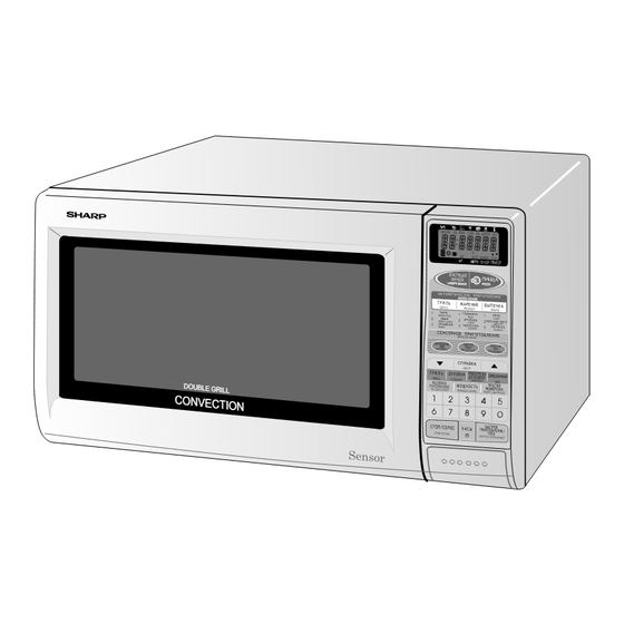
R-870B APPEARANCE VIEW OVEN 1. Oven lamp 2. Top heaters (Grill heaters) 3. See through door 4. Door hinges 5. Door safety latches 6. Door seals and sealing surfaces 7. Bottom heater 8. Oven cavity High rack 9. Turntable motor shaft NOTE: 10.Ventilation openings... -
Page 6: Operation Sequence
Shown in the display is remaining time. Figure O-1 on page 34 6. MONITOR SWITCH CIRCUIT 1. The oven display will show " SHARP MICRO- WAVE The monitor switch is mechanically controlled by the OVEN " . oven door, and monitors the operation of the 1st. latch 2. - Page 7 R-870B the top and bottom heaters. pressing the number pads. When the START pad is pressed, the following operations occur: 3. When the oven temperature reaches the selected preheat temperature, the following operations occur: Figure O-4(a) on page 35 3-1. The heater relays RY3+RY4 de-energized by the 1.
- Page 8 R-870B CONVEC MIX HIGH MODE AND CONVEC MIX LOW pressed, the following operations occur: MODE Figure O-5(b) on page 37 In these modes, the food is cooked by the convection and 1. The relay RY5 + RY6 are energized. the microwave energy. Press the MIX pad once for 2.
- Page 9 R-870B 3. Sensor detects moisture and humidity and calculates Specified cooking Limited power Time base Cooking mode time (minutes) output (%) (seconds) cooking time and variable power. Microwave 100% Power AH SENSOR COOKING SEQUENCE Top heaters 1. In case the AH sensor cooking condition is started, the...
-
Page 10: Function Of Important Components
R-870B motor, turntable motor and the oven lamp. The LSI ON/OFF TIME RATIO also stops counting down. In grill cooking, convection cooking or mix cooking, the top 3. Once the fire sensor feature has shut the unit down, the heaters, bottom heater or magnetron operate whithin a 48 programmed cooking cycle may be resumed by press- second time base. - Page 11 R-870B FUSE M10A 250V NOISE FILTER 1. If the wire harness or electrical components are short- The noise filter assembly prevents radio frequency inter- circuited, this fuse blows to prevent an electric shock or ference that might flow back in the power circuit.
-
Page 12: Servicing
If the water remains cold carry out 3D checks and re-examine the Sharp recommend that wherever possible fault-finding is connections to the component being tested. carried out with the supply disconnected. It may in, some... - Page 13 R-870B...
-
Page 14: Test Procedure
R-870B TEST PROCEDURES PROCEDURE LETTER COMPONENT TEST MAGNETRON TEST NEVER TOUCH ANY PART IN THE CIRCUIT WITH YOUR HAND OR AN INSULATED TOOL WHILE THE OVEN IS IN OPERATION. CARRY OUT 3D CHECKS. Isolate the magnetron from high voltage circuit by removing all leads connected to filament terminal. - Page 15 R-870B TEST PROCEDURES PROCEDURE LETTER COMPONENT TEST Initial temperature ....................T1 = 11°C Temperature after (47 + 2) = 49 sec ..............T2 = 21°C Temperature difference Cold-Warm ............... ∆T1 = 10C Measured output power The equation is “P = 90 x ∆T” ............P = 90 x 10°C = 900 Watts ±...
- Page 16 R-870B TEST PROCEDURES PROCEDURE LETTER COMPONENT TEST B. Continuity check must be carried out with measuring instrument which is set to the highest resistance range. C. A normal capacitor shows continuity for a short time (kick) and then a resistance of about 10MΩ after it has been charged.
- Page 17 R-870B TEST PROCEDURES PROCEDURE LETTER COMPONENT TEST BLOWN FUSE 15A CARRY OUT 3D CHECKS. If the fuse 15A is blown, there could be a short or ground in electrical parts or wire harness. Check them and replace the defective parts or repair the wire harness.
- Page 18 R-870B TEST PROCEDURES PROCEDURE LETTER COMPONENT TEST THERMISTOR TEST 1. CARRY OUT 3D CHECKS. 2. Disconnect connector-D from the control unit. Measure the resistance of the thermistor with an ohmmeter. Connect the ohmmeter leads to Pin No’s D1 and D3.
- Page 19 R-870B TEST PROCEDURES PROCEDURE LETTER COMPONENT TEST (stop switch) is good, disconnect the flat ribbon cable that connects the key unit to the control unit and make sure the door sensing switch is closed (either close the door or short the door sensing switch connecter).
- Page 20 R-870B TEST PROCEDURES PROCEDURE LETTER COMPONENT TEST STEPS OCCURRENCE CAUSE OR CORRECTION The rated AC voltage is not present at Check supply voltage and oven power cord. Power terminal of CPU connector (CN-A). The rated AC voltage is present at primary Low voltage transformer or secondary circuit defective.
- Page 21 R-870B TEST PROCEDURES PROCEDURE LETTER COMPONENT TEST TESTING METHOD FOR AH SENSOR AND/OR CONTROL UNIT To determine if the sensor is defective, the simplest method is to replace it with a new replacement sensor. (1) Disconnect oven from power supply and then remove outer case.
-
Page 22: Touch Control Panel Assembly
R-870B TOUCH CONTROL PANEL ASSEMBLY OUTLINE OF TOUCH CONTROL PANEL The touch control section consists of the following units as 4) ACL shown in the touch control panel circuit. A circuit to generate a signal which resets the LSI to the initial state when power is supplied. - Page 23 R-870B DESCRIPTION OF LSI LSI(IZA936DR) The I/O signal of the LSI(IZA936DR) are detailed in the following table. Pin No. Signal Description Terminal not used. Power source voltage input terminal. Standard voltage for LCD. AN7-AN5 Heating constant compensation terminal. Terminal not used.
- Page 24 R-870B Pin No. Signal Description Key strobe signal. Signal applied to touch-key section. A pulse signal is input to P44 - P47 terminal while one of G8 line key on matrix is touched. Key strobe signal. Signal applied to touch-key section. A pulse signal is input to P44 - P47 terminal while one of G7 line key on matrix is touched.
- Page 25 R-870B Pin No. Signal Description Internal clock oscillation frequency input setting. The internal clock frequency is set by inserting the crystal oscillation circuit with respect to XIN terminal. XOUT Internal clock oscillation frequency control output. Output to control oscillation input of XOUT.
- Page 26 R-870B Pin No. Signal Description 82-90 Segment data signal. SEG8-SEG0 Connected to LCD. Signal is similar to SEG39. Connected to GND. VREF Connected to GND. AVSS Connected to VC. COM3 Common data signal. Connected to LCD (Pin No. 36). No connection in LCD.
- Page 27 R-870B ABSOLUTE HUMIDITY SENSOR CIRCUIT Then the LSI observes that voltage at AN1 terminal and (1) Structure of Absolute Humidity Sensor compares it with its initial value, and when the compari- The absolute humidity sensor includes two thermistors son rate reaches the preset value (fixed for each menu as shown in the illustration.
- Page 28 R-870B SERVICING 1. Precautions for Handling Electronic Components 6) Run the oven and check all functions. This unit uses CMOS LSI in the integral part of the circuits. A. On some models, the power supply cord between the When handling these parts, the following precautions touch control panel and the oven itself is so short that should be strictly followed.
-
Page 29: Component Replacement And Adjustment Procedure
High voltage transformer and Oven cav- To prevent an electric shock, take the following ity. manners. 3) Sharp edge: 1. Before wiring, Bottom plate, Oven cavity, Waveguide flange, 1) Disconnect the power supply. Chassis support and other metallic plate. - Page 30 R-870B oven cavity rear plate. CAUTION: WHEN REPLACING HIGH VOLTAGE REC- TIFIER ASSEMBLY, ENSURE THAT THE 7. Release the capacitor holder from the fan duct. CATHODE (EARTH) CONNECTION IS SE- 8. Remove the capacitor from the capacitor holder. CURELY FIXED TO THE CAPACITOR 9.
-
Page 31: Fan Motor Replacement
R-870B THERMISTOR REMOVAL 1. CARRY OUT 3D CHECKS. 6. Remove the one (1) screw holding the thermistor angle 2. Now, the back plate with the sub back plate should be to the oven cavity rear plate. removed. 7. Remove the thermistor angle together with thermistor from the oven. - Page 32 3. Where the corners have been snipped off, bend corner cover. areas flat. No sharp edge must be evident after re- moval of turntable motor cover. NOTE: The one (1) screw to fit the turntable motor cover 4.
- Page 33 R-870B GRILL HEATERS (TOP HEATERS) REMOVAL 1. CARRY OUT 3D CHECKS. 6. Remove the reflector from the oven cavity by sliding it 2. Remove the one (1) screw holding the exhaust duct to leftward. the oven cavity. 7. Remove the grill heaters and the short terminal to- 2.
- Page 34 R-870B DOOR REPLACEMENT tabs of door frame to seven (7) holes of door panel. REMOVAL 5. Hold the door panel to the door frame with four (4) 1. CARRY OUT 3D CHECKS. screws. 2. Push the open button and open the door slightly.
-
Page 35: Microwave Measurement
R-870B MICROWAVE MEASUREMENT Recommended instruments are: After adjustment of door latch switches, monitor switch NARDA 8100 and door are completed individually or collectively, the NARDA 8200 following leakage test must be performed with a survey instrument and it must be confirmed that the result meets... -
Page 36: Wiring Diagram
R-870B SCHEMATIC NOTE: Indicates components with potential above 250 V. NOTE: CONDITION OF OVEN 1. DOOR CLOSED. OR CLOCK APPEAR ON DISPLAY. NOISE FILTER UNIT FUSE THERMAL CUT-OUT M10A (MG.) CONTROUNIT RY2: 2ND. INTERLOCK RELAY AH SENSOR 2ND. INTERLOCK RELAY CONTROL... - Page 37 R-870B SCHEMATIC NOTE: Indicates components with potential above 250 V. NOTE: CONDITION OF OVEN FOR GRILL COOKING 1. DOOR CLOSED. 2. CONVECTION PAD TOUCHED UNTIL DESIRED TEMPERATURE ON DISPLAY. 3. COOKING TIME PROGRAMMED. 4. STRAT PAD TOUCHED. NOISE FILTER UNIT...
- Page 38 R-870B SCHEMATIC NOTE: CONDITION OF OVEN 1. DOOR CLOSED. 2. GRILL PAD TOUCHED TWICE. 3. COOKING TIME PROGRAMMED. 4. STRAT PAD TOUCHED. NOISE FILTER UNIT FUSE THERMAL CUT-OUT M10A (MG.) CONTROUNIT RY2: 2ND. INTERLOCK RELAY AH SENSOR 2ND. INTERLOCK RELAY CONTROL SWITCH 1ST.
- Page 39 R-870B SCHEMATIC NOTE: CONDITION OF OVEN 1. DOOR CLOSED. NOTE: Indicates components with potential above 250 V. 2. MIX PAD TOUCHED ONCE/TWICE. 3. COOKING TIME PROGRAMMED. NOTE: The microwave relay (RY2) and heater relays (RY3+RY4) could not turn on simultaneously.
-
Page 40: Pictorial Diagram
R-870B... -
Page 41: Power Unit Circuit
R-870B Q2 2SB1238 R4 27 D1-4 R5 4.7k 11ES1 AC220V 50Hz R3 510 1/2w 2SB1238 R2 680 1/2w BUZZER R6 3.3k FAN MOTOR FAN MOTOR CONVECTION CONVECTION MOTOR MOTOR N.O. OVEN LAMP TURNTABLE DTD143ES MOTOR OVEN LAMP TURNTABLE MOTOR 10µ/35v BOTTOM N.O. -
Page 42: Control Panel Circuit
R-870B... -
Page 43: Printed Wiring Board
R-870B CN - C VRS1 CN - A LOT NO. Figure S-4. Printed Wiring Board... -
Page 44: Parts List
R-870B PARTS LIST ∆ Note: The parts marked " " may cause undue microwave exposure. The parts marked "*" are used in voltage more than 250V. REF. NO. PART NO. DESCRIPTION Q'TY CODE ELECTRIC PARTS 1- 1 QSW-MA131WRE0 1st. latch switch, 2nd. interlock relay control switch 1st. - Page 45 R-870B ∆ Note: The parts marked " " may cause undue microwave exposure. The parts marked "*" are used in voltage more than 250V. REF. NO. PART NO. DESCRIPTION Q'TY CODE OVEN PARTS ∆ 4- 1 DOVN-A513WRY0 Oven cavity ∆...
- Page 46 R-870B ∆ Note: The parts marked " " may cause undue microwave exposure. The parts marked "*" are used in voltage more than 250V. REF. NO. PART NO. DESCRIPTION Q'TY CODE SCREWS,NUTS AND WASHERS 7- 1 XFPSD40P08K00 Screw : 4mm x 8mm...
- Page 47 R-870B OVEN AND CABINET PARTS 6-12 4-45 4-33 7-10 4-25 7-12 4-23 4-29 4-26 7-10 7-10 4-37 4-42 1-11 1-20 4-15 1-12 7-17 1-22 7-15 4-30 4-31 7-10 7-13 1-14 7-10 4-34 1-16 7-10 4-40 4-27 1-21 4-19 4-43 4-32...
- Page 48 R-870B CONTROL PANEL PARTS 3-3-3 6-13 DOOR PARTS 3-3-1 3-3-2 MISCELLANEOUS 6-10 6-11 Actual wire harness may be different than illustration. '98SHARP CORP. (8K0.12E) Printed in Japan...
Need help?
Do you have a question about the R-870B and is the answer not in the manual?
Questions and answers