Table of Contents
Advertisement
Restrictions on Disclosure
The information and data furnished in this document are deemed confidential and shall not be
duplicated or disclosed to a third party, either in whole or in part, without the express written consent
of Focal Technologies Corp.
Fiber Optic Video/Data Multiplexer
User's Guide
Part No. 907-0601-00 Rev. C
Copyright © 2011, Focal Technologies Corp.
Moog Components Group, Halifax Operations
Focal Technologies Corporation
77 Frazee Avenue
Dartmouth, Nova Scotia, Canada B3B 1Z4
Tel: 1-902-468-2263 • Fax: 1-902-468-2249
Email: focal@moog.com • www.moog.com/marine
Model 907
June 20, 2011
Advertisement
Table of Contents

Related Manuals for Focal 907

Summary of Contents for Focal 907
- Page 1 Email: focal@moog.com • www.moog.com/marine Model 907 Fiber Optic Video/Data Multiplexer User's Guide Part No. 907-0601-00 Rev. C June 20, 2011 Copyright © 2011, Focal Technologies Corp. Restrictions on Disclosure The information and data furnished in this document are deemed confidential and shall not be duplicated or disclosed to a third party, either in whole or in part, without the express written consent of Focal Technologies Corp.
- Page 2 ACC/IM May 28, 2010 abbreviations. - Updated appendix A (fuses table). - Added appendix B to show a summary of the Model 907 cards with description and configuration drawing part number. - Added new 907-GEM motherboard section. - Update appendix A and B to add fuse and card information of the 907-GEM.
-
Page 3: Table Of Contents
907-GBE2 (Dual Gigabit Ethernet) ....................4-7 907-GBES (Quad Gigabit Ethernet Switch) ................. 4-8 Expansion Cards ..........................5-1 907-EIBS (10 Mbps Ethernet Switch Card) .................. 5-2 907-232 (8-Channel RS-232 Card) ....................5-3 907-485 (8-Channel RS-485/422 Card) ..................5-4 907-SER (8-Channel Serial Data Card) ..................5-5 907-ADC (8-Channel 8/12 bit ADC Card) .................. - Page 4 Figure 3-1: Remote & Console Motherboard Optical Configuration ..............3-1 Figure 3-2: Standard Model 907 Multiplexer Motherboard with WDM ............. 3-2 Figure 3-3: On board I/O Channels for 907-R and 907-C Multiplexer Motherboard Cards ......3-2 Figure 3-4: 907-R & 907-C Multiplexer Card ....................3-3 Figure 3-5: Model 907V Multiplexer Motherboard ...................
- Page 5 Figure 3-16: 907-HDM2-R & 907-HDM2-C Multiplexer Card ................ 3-14 Figure 3-17: Model 907-GEM Multiplexer Motherboard ................3-16 Figure 3-18: On board I/O Channels for 907-GEM-R and 907-GEM-C Multiplexer Motherboard Cards ..3-17 Figure 3-19: 907-GEM-R & 907-GEM-C Multiplexer Card ................3-18 Figure 4-1: Media Converter Card (907-GBES)....................
- Page 6 907-0601-00 Rev. C Model 907 Video/Data Multiplexer – User’s Guide ACRONYMS AND ABBREVIATIONS The list below contains the acronyms and abbreviations used in this user's guide. Adaptable Interface Board Bit Error Rate CWDM Coarse Wavelength Division Multiplexer / Multiplexing Emitter Coupled Logic (Vcc = 0V)
-
Page 7: 1.0 Introduction
Remotely Operated Vehicles (ROV) and other applications requiring the transmission of video and/or data over an optical link. The Model 907 has been optimized for low power operation and delivery of high quality video and data in a standard PC/104 form factor. A flexible design architecture supports modular reconfiguration and expansion of the multiplexer system by changing or adding cards to the system. -
Page 8: 2.0 System Overview
(WDM). Basic systems usually operate with a 1310 nm uplink and 1550 nm downlink. In larger systems, multiple stacks of 907 cards may be combined on a single fiber using a coarse wavelength division multiplexer (CWDM) to take advantage of the high bandwidth of optical fiber. -
Page 9: Figure 2-2: Example Of A Model 907 Stack
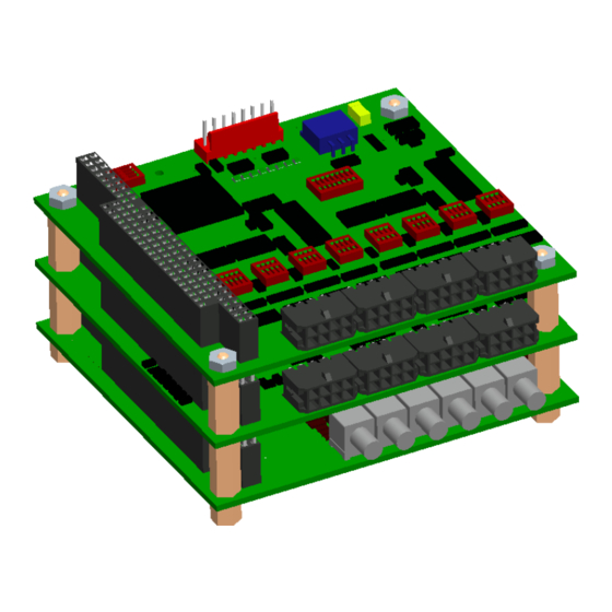
907-0601-00 Rev. C Model 907 Video/Data Multiplexer – User’s Guide An example of a Model 907 stack is shown below in Figure 2-2, in this case a Model 907V motherboard (907-V) with two 8-channel RS-485 expansion cards (907-485). Figure 2-2: Example of a Model 907 Stack Focal Technologies Corp. -
Page 10: 3.0 Multiplexer Motherboard Cards
Model 907 Video/Data Multiplexer – User’s Guide 3.0 Multiplexer Motherboard Cards Both the remote and console ends of the optical link incorporate a 907 motherboard. The motherboards multiplex video and/or data channels, transmit the combined data over the optical link, demultiplex received data from the optical link, store system diagnostic data, and provide power to other cards in the stack. -
Page 11: Standard 907 Multiplexer Motherboard
Figure 3-2 shows a standard Model 907 multiplexer motherboard with an external wavelength division multiplexer (WDM) and Figure 3-3 shows the input/output (I/O) channels for the standard Model 907-R and 907-C multiplexer cards. Figure 3-2: Standard Model 907 Multiplexer Motherboard with WDM... -
Page 12: Remote Multiplexer Card (907-R)
LEDs Only The 907-C is the console half of the 907 motherboard pair and as with the 907-R, fiber access is typically via an ST/PC bushing in the middle of the card, though FC/PC options are available. A 907-C configuration using a WDM is shown in Figure 3-4. -
Page 13: 907V Multiplexer Motherboard
Switch SW2 configures the input video format from any one of eight possible arrangements. Details of the video format options are described in the configuration drawing 907-2026-00. The 907V remote is available in pressure tolerant versions with up to 6000 psi rating. -
Page 14: Figure 3-5: Model 907V Multiplexer Motherboard
907-0601-00 Rev. C Model 907 Video/Data Multiplexer – User’s Guide Figure 3-5 shows a 907V multiplexer motherboard and Figure 3-6 shows the I/O channels for the 907V-R and 907V-C multiplexer motherboard cards. Figure 3-5: Model 907V Multiplexer Motherboard VIDEO IN... -
Page 15: Remote 907V Multiplexer Card (907V-R)
75 ohms, AC-coupled. A 907-DIAG-E diagnostic card may be stacked with the 907V-C to obtain critical system diagnostics of both the remote and console stacks through an Ethernet interface. Details of the 907-DIAG-E card are provided in the System Modules section. -
Page 16: 907Plus Multiplexer Motherboard
Model 907 Video/Data Multiplexer – User’s Guide 907Plus Multiplexer Motherboard The 907Plus (907+) multiplexer motherboard supports four unidirectional video channels, six dedicated bidirectional serial channels (4 x RS-232, 2 x RS-485), and up to six expansion cards via the PC/104 data ports. -
Page 17: Figure 3-8: Model 907Plus Multiplexer Motherboard
907-0601-00 Rev. C Model 907 Video/Data Multiplexer – User’s Guide Figure 3-8 shows a 907Plus multiplexer motherboard and Figure 3-9 shows the I/O channels for the 907+R and 907+C multiplexer cards. Figure 3-8: Model 907Plus Multiplexer Motherboard 2 x RS-485 VIDEO IN CH1&2... -
Page 18: Remote 907Plus Multiplexer Card (907+R)
907-0601-00 Rev. C Model 907 Video/Data Multiplexer – User’s Guide 3.3.1 Remote 907Plus Multiplexer Card (907+R) Card P/N 907-0025-00 Config. Dwg. 907-2035-00 Diagnostics: 907-DIAG-E Compatible Figure 3-10 shows top and side views of the 907Plus remote card. The backplane PC/104 connector allows stacking of other PC/104 form-factor cards. -
Page 19: Console 907Plus Multiplexer Card (907+C)
A 907-DIAG-E diagnostic card may be added to the same stack as the 907+C to obtain critical system diagnostics of both the remote and console stacks through an Ethernet interface. Details of the 907- DIAG-E card are provided in the System Modules section. -
Page 20: 3.4 907-Hdm2 Multiplexer Motherboard
20 dB or greater. In higher budget systems a minimum of 5 dB attenuation is recommended for bench testing to ensure receivers are not saturated. The 907-HDM2 is recommended for singlemode operation only. Please refer to configuration drawing 907-2052-00 for more information. -
Page 21: Table 3-1: 907-Hdm2 Configuration Options (Defaults Shaded)
Model 907 Video/Data Multiplexer – User’s Guide There are three different configurations for the 907-HDM2. They each balance the required video and data inputs with the available optical bandwidth differently as shown in Table 3-1. Native HD-SDI uses 4:2:2 pixel sampling. -
Page 22: Figure 3-14: On Board I/O Channels For 907-Hdm2-R And 907-Hdm2-C
The remote card defaults to HD-SDI channel 1 input but can be switched to channel 2 via the 907-DIAG-E card. This option supports up to six expansion cards and the ancillary data of the HD-SDI signal is embedded in the optical link. -
Page 23: Remote 907-Hdm2 Multiplexer Card (907-Hdm2-R)
907-2052-00 for more information. The 907-HDM2 has an array of diagnostic LEDs for Power, No Link, Link Ready, Video, and Serial Data I/O Activity for each on-board data channel. The power LED is green when the input power voltage is within an acceptable range. -
Page 24: Console 907-Hdm2 Multiplexer Card (907-Hdm2-C)
A 907-DIAG-E diagnostic card may be stacked with the 907-HDM2-C to obtain critical system diagnostics of both the remote and console stacks through an Ethernet interface. More details of the 907-DIAG-E card are provided in the System Modules section. -
Page 25: 3.5 907-Gem Multiplexer Motherboard
SFP optical transceiver. The 907-GEM card allows the use of non-standard frames often used by multibeam sonars (e.g. Reson 7125) and other proprietary data links that require simultaneous yet dedicated point-to-point “switchless”... -
Page 26: Figure 3-18: On Board I/O Channels For 907-Gem-R And 907-Gem-C Multiplexer Motherboard Cards
907-0601-00 Rev. C Model 907 Video/Data Multiplexer – User’s Guide Figure 3-18 shows the I/O channels for the 907-GEM-R and 907-GEM-C multiplexer cards. PORT 1 10/100/1000 Mbps PORT 2 PORT 4 REMOTE CONSOLE PORT 3 10/100/1000 Mbps PORT 3 10/100/1000 Mbps... -
Page 27: Remote 907-Gem Multiplexer Card (907-Gem-R)
907-GEM card and Port Rx Activity LEDs are green when packets are being received into the 907-GEM card. Also, the quad RJ-45 jack of the 907-GEM card has LEDs to indicate the link status of each copper port; the orange LED indicates 10 Mbps, the yellow LED indicates 100 Mbps and the green LED indicates 1000 Mbps. -
Page 28: Console 907-Gem Multiplexer Card (907-Gem-C)
3-19. The console card‟s electrical and optical interfaces are identical to the remote, the only difference is that pin 1 of the dip switch SW1 needs to be set “ON” for remote configuration (907-GEM-R) or “OFF” for console configuration (907-GEM-C). -
Page 29: 4.0 Media Converters
Model 907 Video/Data Multiplexer – User’s Guide 4.0 Media Converters Model 907 media converter cards are PC/104 form-factor modules used to provide optical transmission of high-speed data signals (20-1500 Mbps), such as Ethernet, ECL/PECL for multi-beam sonar links, IEEE-1394 (widely known as “Firewire”) for digital cameras and digital high-definition video (SMPTE-292). Media converters may be deployed as standalone cards using a designated fiber or as CWDM versions that are optically multiplexed with a motherboard or other media converter cards. -
Page 30: 907-Mc (10/100 Mbps Ethernet)
The fiber link is limited to a length of 2 km when half-duplex mode is used, as per IEEE 802.3 standards. If the 907-MC card is configured to use full-duplex mode, the fiber link length is limited only by the optical budget. -
Page 31: 907-1394 (Firewire)
Appropriate replacement fuse part-numbers are provided in the Appendix A. As shown in Figure 4-3, the 907-1394 card has LEDs for Power, Board Reset, Cable-Link, and Optical Signal Detect. The Power LED is on when the board is powered, the Board Reset LED is on momentarily during power up and continuously for an under-voltage input. -
Page 32: 907-Ecl (Sonar)
75 ohms to 50 ohms. The 907-ECL card can be ordered as a standalone card (built with short PC/104 connector pins and a short optical jumper from the SFP transceiver to the optical ST/PC bushing) or as a CWDM stacking version, for integration with a 907 multiplexer or other devices. -
Page 33: 907-Hdv (Hd-Sdi)
The 907-HDV (HD-SDI) media converter card is based on the same printed circuit board assembly as the 907-ECL, but using an SFP transceiver with a higher data rate to support the 1.5 Gbaud signals. At the remote (subsea) end, the camera signal is input at SMB jack J1, as shown in Figure 4-5. At the console end, the HD-SDI monitor or processing equipment is attached to jack J3. -
Page 34: 907-Gbe (Gigabit Ethernet)
Diagnostics: LEDs Only The 907-GBE (Gigabit Ethernet) media converter shown in Figure 4-6 is used to convert a single channel of 10/100/1000 Mbps Ethernet data into optical format at the remote end and vice-versa at the console end. Regardless of the input data rate, the optical link always runs at 1000 Mbps (1250 Mbaud). This “switchless”... -
Page 35: 907-Gbe2 (Dual Gigabit Ethernet)
907-DIAG-E Compatible The 907-GBE2, shown in Figure 4-7, is a Dual Gigabit Ethernet Media Converter and is used to convert two channels of 1000 Mbps Ethernet data into optical format at the remote end and vice-versa at the console end. -
Page 36: 907-Gbes (Quad Gigabit Ethernet Switch)
Figure 4-8: 907-GBES Media Converter Card The 907-GBES card can supply +5 VDC power to other stacked cards or receive +5 V power from other cards in the stack. In this way, the 907-GBES card behaves like a 907 motherboard or a 907 media converter. Each 907-GBES is fuse limited to 5.0 A for on-board current draw plus total current draw from the stacked cards. -
Page 37: 5.0 Expansion Cards
For example, if a 907-485 expansion card is assigned to data port 5, then the channel 5 RS-485/422 channel on the 907 card itself is disabled while the expansion card overrides it. Furthermore, the RS-232 channels (1-4) on the standard 907 card run on dual transceivers, so disabling one channel always disables a second channel, i.e. -
Page 38: 907-Eibs (10 Mbps Ethernet Switch Card)
10/100 Mbps Ethernet linking and are connected to a switching hub chip. A fourth Ethernet port from the hub chip is used to transmit and receive data through one of the six backplane data ports on the Model 907 motherboard. Local traffic between on-board RJ-45 ports is supported and is not transmitted through the optical link. -
Page 39: 907-232 (8-Channel Rs-232 Card)
(8:1), which is transported over a single data port channel on the motherboard. Figure 5-2: 907-232, RS-232 Expansion Card Configure switch SW9 to set the backplane data port used by the 907-232 card. Ports 3~6 are available. The default setting is data port #3. Focal Technologies Corp. -
Page 40: 907-485 (8-Channel Rs-485/422 Card)
To maintain signal integrity at the high data rates, external cables should be shielded twisted pairs with 120-ohm impedance. Figure 5-3: 907-485, RS-485/422 Expansion Card Configure switch SW9 to set the backplane data port used by the 907-485 card. All ports (1~6) are available. The default setting is data port #1. Focal Technologies Corp. -
Page 41: 907-Ser (8-Channel Serial Data Card)
907- DIAG-E card are provided in the System Modules section 6.0. Switch SW1 is used to configure the 907-SER card for either remote or console use, although this is only needed for diagnostics purposes when used with a 907-DIAG-E card. Refer to configuration drawing for switch settings. - Page 42 Model 907 Video/Data Multiplexer – User’s Guide When the card part number used is 907-0242-00, switch SW3 and SW4 are used to configure each channel individually as either RS-232 or RS-485. When the card part number used is 907-0242-01, switch SW3 and SW4 must be set in the ON position (default).
-
Page 43: 907-Adc (8-Channel 8/12 Bit Adc Card)
(8 x 8-bit) or channels 1 through 6 are active (6 x 12-bit). The card may be factory configured for 12-bit resolution. Figure 5-5: 907-ADC Expansion Card Switch SW1 is also used to set the backplane data port used by the 907-ADC card. Ports 1, 3 or 5 are available. The default setting is data port #1. Focal Technologies Corp. -
Page 44: 907-Dac (8-Channel Dac Card)
Dual outputs are provided by connectors J1 - J4 so that channels may be monitored live while also connected to controllers or logging equipment. Switch SW1 is also used to set the backplane data port used by the 907-DAC card. Ports 1, 3 or 5 are available. The default setting is data port #1. -
Page 45: 907-Audio (4-Channel, 24-Bit Audio Card)
The 907 audio transformer board (907-AUDIO-T) allows for easy integration of transformers into a 907 stack. Figure 5-7: 907-AUDIO Expansion Card Configure switch SW13 to set the backplane data port used by the 907-AUDIO card. All ports (1~6) are available. The default setting is data port #1. Focal Technologies Corp. -
Page 46: 907-Audio-T (4- Channel Audio Transformer Card)
The 4-channel 907-AUDIO-T expansion card allows for easy integration of audio transformers into a Model 907 multiplexer stack. It consists of an array of transformers and an array of resistors, as shown in Figure 5-8. The 1:1, 600-ohm impedance transformers can be used to isolate grounds between audio components, or to provide a single ended speaker output from the differential output of the 907-AUDIO expansion card. -
Page 47: 907-Ttl (8-Channel Ttl Card)
5 V TVS diodes and 22-ohm inline resistors. Maximum input and output signal ranges are from -0.5 V to +5.5 V. Configure switch SW9 to set the backplane data port used by the 907-TTL card. Ports 3~6 are available. The default setting is data port #3. -
Page 48: 907-Cib (4-Channel Control Interface Card)
Figure 5-10: 907-CIB Control Channel Expansion Card Configure switch SW9 to set the backplane data port used by the 907-CIB card. All ports (1~6) are available. The 907-CIB may also be configured to transmit the multiplexed channel status over an RS-232 port via connector J9, allowing the 907-CIB cards to operate over a spare RS-232 channel or independent copper link. -
Page 49: 907-420 (6-Channel 4-20 Ma Card)
Diagnostics: None The 907-420 expansion card shown in Figure 5-11 is used to multiplex up to six channels of 4-20 mA inputs. The 4-20 mA input signal is a current-based signaling scheme where 4 mA represents zero percent signal and 20 mA represents the one hundred percent signal. The input current levels are converted to voltages and an ADC is used to digitize the signal. -
Page 50: 907-Usb (Universal Serial Bus Card)
Note: This card is now obsolete and can no longer be ordered. The 907-USB expansion card is a special card used to convert USB signals to Ethernet, and vice-versa. This card is not outfitted with any optical transceivers, and must be used in conjunction with an Ethernet converter card (e.g. -
Page 51: 907-Aib (Dual-Socket Aib Adaptor)
The 907-AIB expansion card allows standard AIB (Adaptable Interface Board) plug-in modules from the Model 903 systems to be employed in Model 907 stacks. Note that to accommodate the length of the plug-in cards, the sides of the 907-AIB extend 0.28‟‟ outside the normal PC/104 form factor as shown in Figure 5-13. -
Page 52: 6.0 System Modules
Switch S1 is used to enable and disable the use of the Model 903 backplane for data I/O to the 907 card. When data I/O is disabled, the Model 903 backplane is only used to supply +5 V power and ground, which supports the use of 907 motherboards and media converters. -
Page 53: Figure 6-2: 907-Euro Eurocard Adaptor Card Assembly
907-0601-00 Rev. C Model 907 Video/Data Multiplexer – User’s Guide The 907 Eurocard adaptor PCBA can be configured with either a 4HP- or 8HP-wide front panel for a 3U Eurocard rack. Figure 6-2 shows a 907-EURO Eurocard adaptor card assembly. -
Page 54: 907-Pc104 (907 To Standard Pc/104 Adaptor)
907-PC/104 Adaptor board must be used to prevent damage. This card provides isolation between the PC/104 backplane and the Focal 907 stack. Only the +5 V pins and the GND pins are connected through the PC/104 connector. Figure 6-3 shows the 907-PC104 adaptor board. -
Page 55: 907-Dc-24 (Isolated Dc-Dc Power Card)
4 A. The aggregate current output of the DC-DC converter should not exceed 8 A. Typically the 907-DC-24 is mounted on the bottom of a stack or installed separately but near the 907 stack. -
Page 56: 907-Cwdm (Cwdm Optics Card)
The 907-CWDM optics card shown in Figure 6-5 is a two-channel CWDM optical add/drop multiplexer (OADM). The 907-CWDM is able to add or drop individual 1471 nm and 1491 nm CWDM wavelengths to an existing 1310/1550 nm (wider band) WDM signal by daisy chaining to the existing fiber link. -
Page 57: 907-Cwdm-4 (4-Channel Cwdm Optics Card)
CWDMs. A typical 907-CWDM-4 optics card, shown in Figure 6-6, is used to optically multiplex four standard CWDM channels with 20 nm spacing from P1, P2, P3, and P4, into a single common optical fiber (COM) for connection to the external fiber system, typically at an ST/PC bushing. -
Page 58: 907-Cwdm-8 (8-Channel Cwdm Optics Card)
2 (blue band) are 1271 / 1291 / 1311 / 1331 / 1351 / 1371 / 1391 / 1411 / 1431 / 1451 nm. Optical insertion loss is typically less than 3 dB per 907-CWDM-8 card. Optical link analysis must account for CWDM cards at both ends of the system. -
Page 59: 907-Fos (1X2 Smf/Mmf Fiber Optic Switch Card)
D2 and D4 are ON when the F3 path is selected. The 907-FOS card can be powered with +5 VDC via the PC/104 backplane or via connector J2 (pin 4 = +5V and pin 6 = GND). The card draws 70 to 90 mA, depending on the switch state – switch position 1 draws the higher current. -
Page 60: 907-Split (1X2 Optical Splitter Card)
Config. Dwg. 907-2031-01 The 907-SPLIT 1x2 optical splitter card, shown in Figure 6-9, is used to split an optical signal for redundant operation. Typically installed at the remote (subsea) end of a 907 system, this card splits the optical power from a multiplexer or media converter card equally into two fiber outputs at F1 and F2. -
Page 61: 907-Diag (Diagnostics Card, Led Driver)
907-2033-XX The 907-DIAG diagnostics interface card is shown below in Figure 6-10. This card monitors the data traffic on the six data ports as well as the video sync lines and optical link line. Ten 6-pin WAGO headers are provided for harnesses to external status LEDs. -
Page 62: 907-Diag-E (Diagnostics Card, Ethernet)
In addition to providing a full protocol description for user-implementation of a software interface to the 907-DIAG-E system, Focal Technologies has created a .NET library and a sample Graphical User Interface for displaying system diagnostics on a Windows-based PC. Refer to the Diagnostic Protocol Manual, 700-0739-00, and the Diagnostic Software Manual, 907-0604-00, for more details on the card capabilities, interfaces, protocol description, and available software development tools. -
Page 63: Table 6-1: 907 Cards Compatible With 907-Diag-E
907-0601-00 Rev. C Model 907 Video/Data Multiplexer – User’s Guide The following table shows a list of the Model 907 cards that are compatible with the 907-DIAG-E card. Table 6-1: 907 Cards Compatible with 907-DIAG-E Card Description 907V 907V Multiplexer Motherboard... -
Page 64: 7.0 Fiber Optic System
Figure 7-1: Example Optical Configurations Safety All lasers used in the Model 907 system are Class I laser devices per IEC-60825 unless otherwise specified in installation or configuration drawing. No special control measures or warning labels are required, although any needless exposure of the eye should be avoided as a matter of good practice, and fibers should never be viewed with magnifying instruments, e.g. -
Page 65: System Design
WDMs and couplers are taken into account. Any remaining power is the optical power margin. Some margin should be allocated for temperature and aging effects, typically 4-6 dB. Minimum flux budgets for 907-based systems range from 16 dB to 26 dB available to the external cables, connectors, FORJs, etc. -
Page 66: 8.0 Installation And Operation
8.0 Installation and Operation Mounting Model 907 cards use the standard PC/104 form factor of 3.55 × 3.775 inches (90 × 96 mm). The cards are outfitted with a PC/104 keyed connector to provide backplane connectivity between multiple cards assembled in a vertical stack. -
Page 67: Power
All Model 907 cards require a regulated +5 VDC. The tolerance varies from card to card, but is typically ±5% to ±10%. Current draw varies from card to card, and the total current draw for a stack (if drawn from the motherboard) must be calculated to ensure it does not exceed the fuse rating of the motherboard. -
Page 68: Maintenance
Always replace dust caps on the Model 907 fiber optic bushings when removing connectors. If bushings are left open, they should be cleared of dust with compressed air prior to reconnection. Fiber jumpers and pigtails should be periodically inspected for damage, such as nicks in the jackets or excessive bends. -
Page 69: Appendices
907-0601-00 Rev. C Model 907 Video/Data Multiplexer – User’s Guide Appendices Appendix A – Fuses Current Card Type Card Qty. Fuse P/N Comments Rating 0452002 2.0 A Replaceable SMT fuse for +5 VDC from power connector (F1) 907+ 0452002 2.0 A... -
Page 70: Appendix B - Model 907 Cards
907-0601-00 Rev. C Model 907 Video/Data Multiplexer – User’s Guide Appendix B – Model 907 Cards Card Type Card Description Config. Dwg. Standard 907 Multiplexer Motherboard 907-2001-00 907V 907V Multiplexer Motherboard 907-2026-00 907-2035-00 (907+ R) 907+ 907Plus Multiplexer Motherboard Multiplexer... -
Page 71: Appendix C - Model 907 Power Current
907-0601-00 Rev. C Model 907 Video/Data Multiplexer – User’s Guide Appendix C – Model 907 Power Current POWER CARD CONFIG. POWER CURRENT (AMPS) POWER CONSUMPTION (WATTS) VOLTAGE CARD ID DESCRIPTION CARD P/N TYPE DWG. Standard 907 Multiplexer 907-0001-02 907-2001-00 0.70 1.00...
Need help?
Do you have a question about the 907 and is the answer not in the manual?
Questions and answers