Advertisement
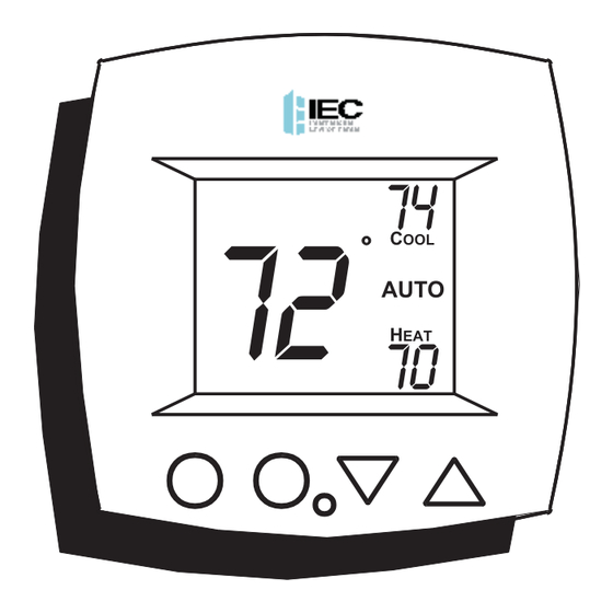
INSTALLATION
INSTRUCTIONS
NON-PROGRAMMABLE
DIGITAL THERMOSTAT
2- OR 4-PIPE
Auto-Changeover is available in 4-pipe systems,
in 2-pipe systems with Electric Heat, or when
used with G100-71520306 accessory, auto-
changeover sensor.
Copyright 2007, International
Environmental Corp. All Rights Reserved
P/N E055-71520301
P/N E055-71520304
FAN COIL
74
72
C
OOL
AUTO
70
H
EAT
NON-PROGRAMMABLE
Advertisement

Subscribe to Our Youtube Channel
Related Manuals for IEC E055-71520301


Summary of Contents for IEC E055-71520301
- Page 1 P/N E055-71520301 INSTALLATION INSTRUCTIONS P/N E055-71520304 FAN COIL NON-PROGRAMMABLE DIGITAL THERMOSTAT AUTO 2- OR 4-PIPE NON-PROGRAMMABLE Auto-Changeover is available in 4-pipe systems, in 2-pipe systems with Electric Heat, or when used with G100-71520306 accessory, auto- changeover sensor. Copyright 2007, International...
-
Page 2: Table Of Contents
Trouble Shooting Warranty CAUTION Follow Installation Instructions carefully. Disconnect Power to the Heater/Air Conditioner WARNING before removing the old therm- ostat and installing the new thermostat. P/N E055-71520301 and P/N E055-71520304 Copyright 2007, International Environmental Corp. All Rights Reserved Page 1... -
Page 3: Step #1: Preparation
STEP #1 PREPARATION Proper installation of the thermostat will be accomplished by following these step by step instructions. If you are unsure about any of these steps, call a qualified technician for assistance. Assemble tools. Drill with 3/16 inch Drill Bit (when not Flat Blade Wire cutter... -
Page 4: Step #2 Remove & Replace Old Thermostat
STEP #2 REMOVE & REPLACE OLD THERMOSTAT (IF APPLICABLE) Remove the cover of the old thermostat. If it does not come off easily check for screws. Loosen the screws holding the thermostat base or subbase to the wall and lift away. Disconnect the wires from the old thermostat. -
Page 5: Step #3 Wire Connections
STEP #3 WIRE CONNECTIONS If the terminal designations on your old thermostat do not match those on the new thermostat, refer to the chart below, or the wiring diagrams that follow. 4-PIPE SYSTEMS Wire from the Install on the old thermostat Function new thermostat terminal marked... - Page 6 STEP #3 WIRE CONNECTIONS If the terminal designations on your old thermostat do not match those on the new thermostat, refer to the chart below, or the wiring diagrams that follow. 2-PIPE SYSTEMS Wire from the Install on the old thermostat Function new thermostat terminal marked...
-
Page 7: Sample Wiring Diagrams
Sample Wiring Diagram 4-Pipe, 2 Relay Boards, Line Voltage Water Valves 24vac G2(W) G2/(W) Thermostat G3(Y) G3/(Y) (VALVE) VALVE (COOL) (HEAT) E025-71520303 G2(W) G2/(W) G3(Y) G3/(Y) (VALVE) (COOL) (HEAT) Page 6... - Page 8 Sample Wiring Diagram 4-Pipe, Low Voltage Valves, Duct Temperature Sensor & Dry Contact Duct Sensor Important Note: If a Duct sensor is conn- G100-71520307 ected to this thermostat RS+5 it is suggested that the fan be programmed for RS GND continuous operation (step #5, page 11 of the Owner’s Manual).
- Page 9 Sample Wiring Diagram 2-Pipe, Low Voltage Valve, Heat Only or Cool Only 24vac 24 Volt Water Valve Thermostat G2(W) G2/(W) G3(Y) G3/(Y) (VALVE) (COOL) (HEAT) E025-71520303 Page 8...
- Page 10 Sample Wiring Diagram 2-Pipe, Low Voltage Valve, H2O Changeover Sensor Duct Sensor Important Note: If a Duct sensor is conn- G100-71520307 ected to this thermostat RS+5 it is suggested that the fan be programmed for RS GND continuous operation (step #5, page 11 of the Owner’s Manual).
- Page 11 Sample Wiring Diagram 2-Pipe, Low Voltage Valve, Chilled Water with Electric Strip Heat 24vac 24 Volt Cold Water Valve 24 Volt Relay to Thermostat Control Strip Heater G2(W) G2/(W) G3(Y) G3/(Y) (VALVE) (COOL) (HEAT) E025-71520303 Page 10...
-
Page 12: Step #4 Test Operation
STEP #4 TEST OPERATION 4-PIPE SYSTEM Turn the power on to the Fan Coil Unit. Press the MODE button repeatedly until the HEAT icon appears on the display. Press the UP or DOWN buttons until the set temperature is 10 degrees above room temperature. - Page 13 STEP #4 TEST OPERATION 2-PIPE, CHANGEOVER SENSOR, NO STRIP HEAT Turn the power on to the Fan Coil Unit and confirm that the thermostat is programmed correctly in setup steps #3 and #4 on page 11 of the Owner’s Manual. If hot water is available, press the MODE button repeatedly until the HEAT icon appears on the display.
- Page 14 STEP #4 TEST OPERATION 2-PIPE, NO CHANGEOVER SENSOR Turn the power on to the Fan Coil Unit and confirm that the thermostat is programmed correctly in setup steps #3 and #4 on page 11 of the Owner’s Manual. If hot water is available, press the MODE button repeatedly until the HEAT icon appears on the display.
- Page 15 STEP #4 TEST OPERATION 2-PIPE, CHANGEOVER SENSOR, WITH STRIP HEAT Turn the power on to the Fan Coil Unit and confirm that the thermostat is programmed correctly in setup steps #3 and #4 on page 11 of the Owner’s Manual. If hot water is available, press the MODE button repeatedly until the HEAT icon appears on the display.
- Page 16 STEP #4 TEST OPERATION 2-PIPE, CHANGEOVER SENSOR, WITH STRIP HEAT Press the UP button until the setpoint is equal to the room temperature. Press the Fan button repeatedly until a single bar appears next to the Fan icon. Confirm the fan is running on low speed.
-
Page 17: Troubleshooting
TROUBLESHOOTING SYMPTOM: The fan will not run in all three speeds or switches speeds in an improper order. CAUSE: Incorrect wiring between the thermostat and the relay board, or between the relay board and the fan wires. REMEDY: Recheck the wiring (G=low speed, G2=medium speed, G3=high speed). - Page 18 TROUBLESHOOTING SYMPTOM: The thermostat displays large set- point digits instead of the room temperature. CAUSE: The thermostat has been programmed to display Single Setpoint. REMEDY: Program the thermostat to display Dual Setpoint (step #2, page 10 of the Owner’s Manual). SYMPTOM: The thermostat display is stuck in Unoccupied.
-
Page 19: Warranty
4Z95 P/N 88-572 I100-90006967 Rev. 2 P.O. Box 2598 • Oklahoma City, OK 73101-2598 • 405.605.5000 [phone] • 405.605.5001 [fax] • www.iec-okc.com ©2007 International Environmental Corporation (IEC). IEC is a subsidiary of LSB Industries, Inc. - AMEX symbol LXU; www.lsb-okc.com...
Need help?
Do you have a question about the E055-71520301 and is the answer not in the manual?
Questions and answers