Table of Contents
Advertisement
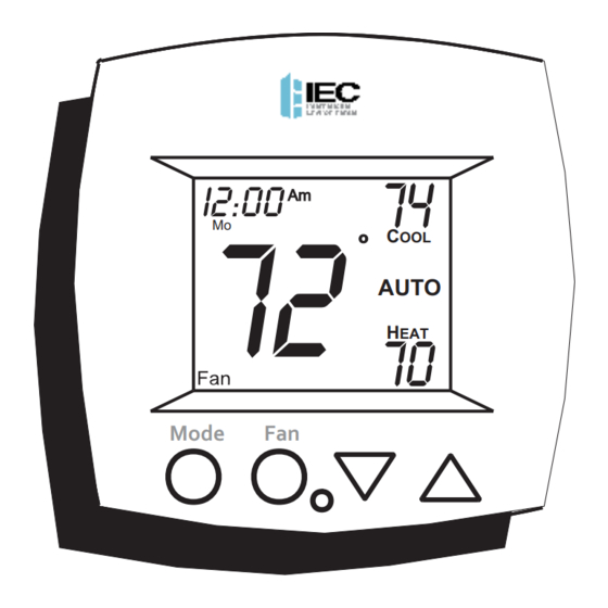
OWNER'S MANUAL
PROGRAMMABLE
DIGITAL THERMOSTAT
74
I2:00
Am
72
Mo
C
OOL
AUTO
70
H
EAT
Mode
Fan
Auto-Changeover is available in 4-pipe systems,
in 2-pipe systems with Electric Heat, or when
used with G100-71520306 accessory, auto-
changeover sensor.
International Environmental Corp.
Copyright 2020, All Rights Reserved
P/N E055-71520317
P/N E055-71520319
FAN COIL
2- or 4-pipe configurable
Dual or Single Setpoint
7 Day Programmable
3 Occupied, 1 Unoccupied
Easy to program
Large, easy to read display
Soft-Glow Backlight
Auto-Changeover
Locking Keypad
Override capable
w/logo
no logo
Advertisement
Table of Contents

Subscribe to Our Youtube Channel
Related Manuals for IEC E055-71520317


Summary of Contents for IEC E055-71520317
- Page 1 P/N E055-71520317 w/logo OWNER'S MANUAL P/N E055-71520319 no logo FAN COIL PROGRAMMABLE DIGITAL THERMOSTAT 2- or 4-pipe configurable Dual or Single Setpoint 7 Day Programmable I2:00 3 Occupied, 1 Unoccupied Easy to program AUTO Large, easy to read display Soft-Glow Backlight...
-
Page 2: Table Of Contents
& OPERATION WARRANTY CAUTION Follow Installation Instructions carefully. Disconnect Power to the Heater/Air Conditioner WARNING before removing the old therm- ostat and installing the new thermostat. P/N E055-71520317 and P/N E055-71520319 International Environmental Corp. Copyright 2019, All Rights Reserved Page 1... -
Page 3: Front Panel
Front Panel I2:00 AUTO Mode Liquid Crystal Display Up/Down Buttons Mode Button Fan/Override Button Heat or Cool Indicator Heat = Red, Cool = Green Page 2... -
Page 4: Display
Display UTSIDE Mode Indicators - Page 7-10 Selects the operational mode of the equipment. HEAT - Indicates the heating mode. COOL - Indicates the cooling mode. AUTO - Indicates the system will automatically changeover between heat and cool modes as the temperature varies. PROGRAM ON - Indicates the time period program is enabled to run. - Page 5 Display I2:00 Start Stop SuMoTuWeThFrSa Setup unoccupied Locked Override AUTO UTSIDE Override icon - Pages 12 & 21 Indicates the program is currently being overridden for up to six hours. Occupied & Unoccupied icons - Pages 13-16 Indicates the program number: Occupied 1,2,3 or Unoccupied.
- Page 6 Display I2:00 Start Stop SuMoTuWeThFrSa Setup unoccupied Locked Override AUTO UTSIDE Start & Stop icons - Pages 14-16 Appear when programming occupied time periods. Locked icon - Page 30 Indicates keypad has been locked. Outside icon - Pages 21 & 31 Indicates the temperature displayed is from the optional outside sensor.
-
Page 7: Quick Start Set The Clock And Go
Quick Start Set the Clock and Go Press the MODE and FAN buttons MODE at the same time for two seconds to enter Setup screens. During Setup and Programming: Pressing the UP or Setting the Clock DOWN button will Tip: To change modify the flashing I2:00 hours quickly,... -
Page 8: Selecting The Heat Or Cool Mode
Selecting the Heat or Cool Mode 4-Pipe Operation Select Mode by Pressing the MODE Button I2:00 Heating Only The HEAT setting indicates the temperature the room has to reach before the Press heating source will turn on to heat the room. MODE I2:00 Cooling Only... - Page 9 Selecting the Heat or Cool Mode 2-Pipe Operation Heat Only See Step #6 on page 19. In the Advanced Setup Section, select option 1: Heat only system. I2:00 Heating Only The HEAT setting indicates the temperature the room has to reach before the heating source will turn on to heat the room.
- Page 10 Selecting the Heat or Cool Mode 2-Pipe Operation Cool Only See Step #6 on page 19. In the Advanced Setup Section, select option 2: Cool only system. I2:00 Cooling Only The COOL setting indicates the temperature the room has to reach before the cooling source will turn on to cool the room.
- Page 11 Selecting the Heat or Cool Mode 2-Pipe Operation Heating and/or Cooling Step #6 = 3 in Advanced Setup (page 19), and the accessory changeover sensor (G100-71520306) is used. Step #6 = 4 or 5 in Advanced Setup (page 19). Operation is the same as a 4-pipe system (page 7). I2:00 HEAT indicates the temperature the room has to reach before the...
-
Page 12: Basic Operation
Basic Operation Selecting Your Desired Temperature (adjusting the setpoints) AUTO OR PROGRAM MODE Pressing the UP or DOWN button in Auto or Program mode will adjust both the heat and cool set temperatures simultaneously. Adjust the desired I2:00 set temperature with the AUTO buttons. -
Page 13: Overriding The Daily Schedule
Basic Operation Overriding the Daily Schedule Pressing and holding the FAN button for 5 seconds may be used to interrupt the normal time schedule programming of the thermostat. The override feature may only be used when the thermostat is running the time schedule, in Program On mode. -
Page 14: Programming Occupied / Unoccupied
Programming Occupied & Unoccupied Periods Press the MODE button. While holding MODE, press the UP button for two MODE seconds to enter time period programming. Select the maximum # of occupied periods to be occupied used on any one day. Typically, most installations use only Occupied 1. - Page 15 Programming Occupied & Unoccupied Periods Adjust the heating set- unoccupied point for Unoccupied periods. (OF, 35 - 99 ) Press MODE Select day of the occupied week for Occupied 1. (Mo - Su) Press MODE 7:00 Start occupied Adjust the start time for Occupied 1.
- Page 16 Programming Occupied & Unoccupied Periods The copy command becomes available after the maximum # of occupied periods are programmed in a day. This example uses 1 as the maximum occupied periods ever programmed in one day. Select Yes or No to copy t h e p r e v i o u s d a y ’s program to this day.
- Page 17 Programming Occupied & Unoccupied Periods 5:00 Stop occupied Adjust the stop time for occupied 1. Select Occupied 1 to occupied run on this day (On), or not to run this day (Off). Press MODE Select Yes or No to copy the previous day’s program to this day.
- Page 18 Programming Occupied & Unoccupied Periods PROGRAMMING NOTES You will be prompted to enter both heat and cool setpoints even if the thermostat is configured for heat only, or cool only. If only 1 Occupied period is selected, the Occupied 2 & 3 steps will be skipped.
-
Page 19: Advanced Setup
Advanced Setup NOTE: Each step Press the MODE and MODE # is located at the FAN buttons at the top right corner of same time for 10 the display for easy seconds to enter reference. A d v a n c e d S e t u p screens. - Page 20 Advanced Setup Select Display operation: Setup 1 = Single Setpoint 2 = Dual Setpoint See Page 32 Note: When Single Setpoint is selected, the heating or cooling setpoint will always be displayed. To display the room temperature, press and hold the MODE Press button for two seconds.
- Page 21 Advanced Setup Select operation when fan is in the Auto mode: On = continuous low speed fan AUTO Off = only energize during a heating or cooling cycle. Press MODE See Page 28, Note #2 Adjust the deadband Setup for the 1st stage. (1 - 6 ) Press See Page 25...
- Page 22 Advanced Setup Setup Select thermostat operation in degrees Fahrenheit or Celsius. Press MODE Sensor Reading Setup Select sensor operation: On = Temp reading at thermostat UTSIDE Off = Temp reading at Press duct sensor MODE 2 00 Adjust the amount of Setup time override will be a c t i v e d u r i n g t h e...
- Page 23 Advanced Setup Occupied Setup Select Dry Contact operation: occupied Occupied = the thermo- stat will enter the Occup- ied mode when the Dry Contact Contact is closed. Unocc- upied Unoccupied = the thermostat will enter the Unoccupied mode when the Dry Contact is closed. Step #16 only appears if step #15 = Unoccupied.
- Page 24 Advanced Setup Advanced Setup Table Step Factory Description Range Default Time of Day 24 hour 12:00 am Day of the Week Mo - Su Display Blanking On / Off Single or Dual Setpoint 1 / 2 2- or 4-Pipe System 2 / 4 2-Pipe System Operation 1 - 5...
-
Page 25: About Advanced Features & Operation
About Advanced Features & Operation CALIBRATION - Under normal circumstances it will not be necessary to adjust the calibration of the temperature sensor. If calibration is required, please contact a trained HVAC technician to correctly perform the following procedure. I2:00 MODE Place the thermostat in the OFF mode. - Page 26 About Advanced Features & Operation DEADBAND OPERATION - Controls one Heat and one Cool stage with a three speed fan (see below). The low speed fan for heat or cool is turned on when: The temperature spread from the setpoint is equal to or greater than: the setpoint plus the 1st stage dead- band (step #8, page 20).
- Page 27 About Advanced Features & Operation DRY CONTACT SWITCH - This feature allows an external device such as a Central Time Clock, Occu- pancy Sensor, or a Telephone activated device to force one or more thermostats into Occupied 1 or Unoccup- ied (steps #14 and 15, page 21-22).
- Page 28 Dry Contact use note of caution Auxiliary Input Control and Multiple HVAC Control Potential Phasing Problems CAUTION WARNING When using the auxiliary input (CK1 & R) or controlling multiple HVAC units with a single thermostat, it is possible to encounter transformer phasing problems that will interfere with thermostat operation.
- Page 29 About Advanced Features & Operation FACTORY DEFAULTS - If, for any reason, you desire to return all the stored settings back to the factory default settings, follow the instructions below. WARNING: This will reset all Time Period and Ad- vanced Programming to the default settings. Any information entered prior to this reset will be permanently lost.
- Page 30 About Advanced Features & Operation FAN OPERATION - Fan operation is available in four different modes: Fan: When only the fan icon is displayed, this indicates that the fan is in the Auto mode, will only energize during a heating or cooling cycle, and will modulate fan speeds based on temperature demand (see page 25).
- Page 31 About Advanced Features & Operation ENERGY SAVING SMART FAN - This feature auto- matically de-energizes the fan during an Unoccupied time period, except when necessary to heat or cool (see page 28). I2:00 unoccupied Note: The fan will not de-energize during an Un- occupied time period if it has been programmed for continuous operation (step #7, page 20).
- Page 32 About Advanced Features & Operation KEYPAD LOCKOUT - To prevent unauthorized use of the thermostat, the front panel buttons may be disabled. To disable, or ‘lock’ the keypad, press and hold the MODE button. While holding the MODE button, press the UP and DOWN buttons together.
- Page 33 About Advanced Features & Operation OUTSIDE SENSOR - To view an Outside Sensor (step #12, page 21), enter the Advanced Setup by pressing and holding the MODE button. While holding MODE, press the FAN button for 5 seconds to enter Setup screens. Advance to setup step #12 by repeatedly pressing the MODE button.
- Page 34 About Advanced Features & Operation SINGLE SETPOINT BEHAVIOR - When configured for Single Setpoint operation (step #4, page 19), the degree icon will blink when the large number is display- ing room temperature and will remain solid when dis- playing the heating or cooling setpoint. In the Auto and Program On modes the deadband is enforced both above and below the setpoint.
-
Page 35: Warranty
PURCHASER. ALL PRICES ARE F.O.B. IEC'S FACTORY WITH FULL FREIGHT ALLOWED UNLESS NOTED OTHERWISE BY IEC. TITLE TO AND RISK OF LOSS TO THE GOODS PASSES TO THE PURCHASER WHEN DELIVERED TO THE CARRIER F.O.B. IEC'S SHIPPING POINT. PURCHASER MUST INSPECT THE GOODS UPON ARRIVAL. - Page 36 (c.) IN THE EVENT OF A BREACH OF THE ABOVE WARRANTY OR NEGLIGENCE ON THE PART OF IEC, IEC SHALL ONLY BE OBLIGATED TO EITHER REPAIR OR REPLACE, AT IEC'S OPTION, THE GOODS, AND THE AFORESAID OBLIGATION OF IEC TO REPAIR OR REPLACE THE GOODS IS THE PURCHASER'S EXCLUSIVE REMEDY.
- Page 37 MAY BE LEVIED BY ANY TAXING AUTHORITY AS A RESULT OF THIS TRANSACTION SHALL BE PAID BY THE PURCHASER. 10. UNLESS OTHERWISE AGREED TO IN WRITING BY IEC, ANY TECHNICAL DATA, FURNISHED IN CONJUNCTION WITH THIS ORDER AND NOT OBTAINABLE FROM ANOTHER SOURCE SHALL NOT BE DUPLICATED, USED, OR DISCLOSED IN WHOLE OR IN PART FOR ANY PURPOSE OTHER THAN TO EVALUATE THIS ORDER.
- Page 38 Where reasonable, safe, and compliant with local regulatory and legal requirements, IEC encourages recycling materials when disposing of its products. 88-1362 I100-90030976 Rev. 4 5000 W I-40 Service Rd.• Oklahoma City, OK 73128 • 405.605.5000 [phone] • 405.605.5001 [fax] • www.iec-okc.com ©2019 International Environmental Corporation (IEC).
Need help?
Do you have a question about the E055-71520317 and is the answer not in the manual?
Questions and answers