Advertisement
Advertisement
Table of Contents

Subscribe to Our Youtube Channel
Related Manuals for Harbor Freight Tools Central Pneumatic


Summary of Contents for Harbor Freight Tools Central Pneumatic
-
Page 2: Table Of Contents
Table of contents Safety ............2 Maintenance ..........14 Specifications ..........7 Parts List and Diagram ......18 Setup ............9 Warranty ............ 20 Operation ........... 12 WARNING SyMBOLS AND DEFINITIONS This is the safety alert symbol. It is used to alert you to potential personal injury hazards. -
Page 3: Work Area
IMpORTANT SAFETy INSTRUcTIONS INSTRUcTIONS pERTAINING TO A RISK OF FIRE, ELEcTRIc SHOcK, OR INJURy TO pERSONS WARNING – When using tools, basic precautions should always be followed, including the following: General To reduce the risks of electric shock, fire, and injury to persons, read all the instructions before using the tool. -
Page 4: Tool Use And Care
Tool use and care a. Use clamps or another practical way to secure Maintain the tool with care. and support the workpiece to a stable platform. A properly maintained tool reduces the Holding the work by hand or against the body risk of binding and is easier to control. - Page 5 Specific Safety Instructions 1. Operators and others in work area MUST 18. Transport tool safely. Always disconnect air wear ANSI-approved safety goggles with supply when moving the tool. Carry the tool by side shields during use. The employer is the handle and avoid contact with the trigger. responsible to enforce the use of eye protection 19.
- Page 6 Vibration precautions This tool vibrates during use. 2. Do not smoke during use. Nicotine reduces Repeated or long-term exposure to vibration may the blood supply to the hands and fingers, cause temporary or permanent physical injury, increasing the risk of vibration-related injury. particularly to the hands, arms and shoulders.
-
Page 7: Specifications
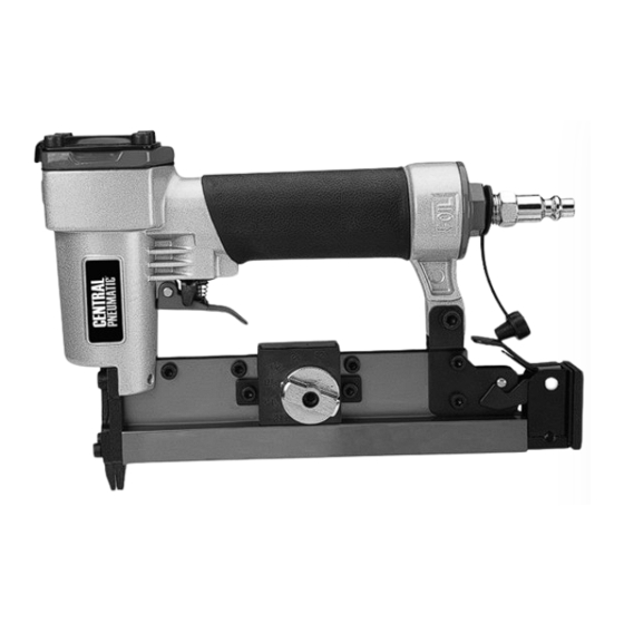
Functional Description Specifications Maximum Air Pressure 100 PSI Air Inlet 1/4"–18 NPT Air Consumption 0.75 CFM @ 90 PSI Nail Type 23 gauge, 1/2"–1" long Pin Nails Item 60664 For technical questions, please call 1-800-444-3353. Page 7... - Page 8 components and controls Trigger Air Inlet Safety Lock plug Trigger Magazine Lock cover plate Nail Length Drive Guide Magazine Adjustment Knob Page 8 For technical questions, please call 1-800-444-3353. Item 60664...
-
Page 9: Setup
Initial Tool Set Up/Assembly Read the ENTIRE IMpORTANT SAFETy INFORMATION section at the beginning of this manual including all text under subheadings therein before set up or use of this product. Note: For additional information regarding the parts listed in the following pages, refer to the Assembly Diagram near the end of this manual. - Page 10 Page 10 For technical questions, please call 1-800-444-3353. Item 60664...
- Page 11 Item 60664 For technical questions, please call 1-800-444-3353. Page 11...
-
Page 12: Operation
Operating Instructions Read the ENTIRE IMpORTANT SAFETy INFORMATION section at the beginning of this manual including all text under subheadings therein before set up or use of this product. Inspect tool before use, looking for damaged, loose, and missing parts. If any problems are found, do not use tool until repaired. - Page 13 General Operating Instructions 1. If an automatic oiler is not used, add 4. If the tool requires more force to accomplish a few drops of Pneumatic Tool Oil to the airline the task, verify that the tool receives sufficient, connection before use. Add a few drops unobstructed airflow (CFM) and increase the more after each hour of continual use.
-
Page 14: Maintenance
User-Maintenance Instructions procedures not specifically explained in this manual must be performed only by a qualified technician. TO pREVENT SERIOUS INJURy FROM AccIDENTAL OpERATION, BEFORE ANy MAINTENANcE OR REpAIRS ARE DONE (including clearing jams): • Wear ANSI-approved safety goggles with side shields. Other people in the work area must also wear ANSI-approved impact safety goggles with side shields. -
Page 15: Clearing Jams
clearing Jams TO pREVENT SERIOUS INJURy FROM AccIDENTAL OpERATION, BEFORE ANy MAINTENANcE OR REpAIRS ARE DONE (including clearing jams): • Wear ANSI-approved safety goggles with side shields. Other people in the work area must also wear ANSI-approved impact safety goggles with side shields. • Release the trigger. -
Page 16: Troubleshooting
Troubleshooting problem possible causes Likely Solutions Insufficient 1. Incorrect tool depth setting. 1. Adjust depth setting, if available. fastener depth. 2. Not enough air pressure. 2. Check for loose connections and make sure that air supply is providing enough air pressure (PSI) to the tool’s air inlet. - Page 17 pLEASE READ THE FOLLOWING cAREFULLy THE MANUFACTURER AND/OR DISTRIBUTOR HAS PROVIDED THE PARTS LIST AND ASSEMBLY DIAGRAM IN THIS MANUAL AS A REFERENCE TOOL ONLY. NEITHER THE MANUFACTURER OR DISTRIBUTOR MAKES ANY REPRESENTATION OR WARRANTY OF ANY KIND TO THE BUYER THAT HE OR SHE IS QUALIFIED TO MAKE ANY REPAIRS TO THE PRODUCT, OR THAT HE OR SHE IS QUALIFIED TO REPLACE ANY PARTS OF THE PRODUCT.
-
Page 18: Parts List And Diagram
parts List and Diagram parts List part Description part Description Bolt M5 x 20 Bolt M5 x 16 Exhaust Cap Bolt M4 x 10 Washer Drive Guide Compression Spring Nut M4 O-Ring Left Magazine Cylinder Cap Adjusting Plate Cylinder Cap Seal Nail Length Adjusting Piece Valve Right Magazine... - Page 19 Assembly Diagram Item 60664 For technical questions, please call 1-800-444-3353. Page 19...
-
Page 20: Warranty
Limited 90 Day Warranty Harbor Freight Tools Co. makes every effort to assure that its products meet high quality and durability standards, and warrants to the original purchaser that this product is free from defects in materials and workmanship for the period of 90 days from the date of purchase.
Need help?
Do you have a question about the Central Pneumatic and is the answer not in the manual?
Questions and answers
What size “O rings does central pneumatic model W32870 brad tacker take