
Subscribe to Our Youtube Channel
Related Manuals for System Q CCT287

Summary of Contents for System Q CCT287
- Page 1 Order Code: CCT287 16-way Duplex Colour Multiplexer V1.1 -02/07/03 16-way Colour Duplex Multiplexer Instruction Manual Version 1.1 E-mail: support@systemq.com or Fax: 01246 222 888...
- Page 2 There are no user-serviceable parts inside. Please contact a qualified engineer for servicing and maintenance. Do not expose the CCT287 to water or moisture and do not try to operate it in wet areas. Please make sure that both ends of the power lead are plugged in.
-
Page 3: Table Of Contents
Contents 1. General Description..................4 2. Features..................... 5 3. System Installation ..................6 3.1 Basic Connections ................6 3.2 Optional Connections................6 4. Basic Operation ..................7 4.1 Front and Rear Panel 16CH Model ............7 4.2 Function Keys Description ..............8 4.3 Alarm History Log................ - Page 4 5.9.5 Rec Density ................20 5.9.6 Sync-Trig Edge ............... 21 5.9.7 Playback Adjust ..............21 5.9.8 VCR Input Check ..............21 5.9.9 Recorder Type ................ 21 5.9.10 VCR Output ................21 Appendix A. Connector Pin Assignment ............22 Appendix B. Technical Specifications .............. 23 E-mail: support@systemq.com or Fax: 01246 222 888 Page - 3 -...
-
Page 5: General Description
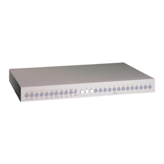
1. General Information The CCT287 multiplexer allows simultaneously recording of multiple full-sized camera pictures on to one VCR tape to provide more comprehensive recorded surveillance than a quadsplitter or switcher unit. The unit has multiple display options full screen, quad, 9-camera, 16-camera as well as a full screen switching mode allowing flexible surveillance of more than one camera whilst all the cameras connected to the unit are being recorded. -
Page 6: Features
2. Features • Duplex operation allows 2 time-lapse VCRs to be connected to the unit at the same time, one for recording LIVE pictures and the other for viewing recorded images. • Outstanding picture quality (720x512 pixel display, 256 grayscale levels and 16 million colors). -
Page 7: System Installation
Video In connection on the monitor. Usually a BNC connection or a 4-pin mini-din for S-VHS use. • Power Connect the DC 12V /1.2AMP adapter to the DC jack on the CCT287’s rear. 3.2 Optional Connections • VCR Connect the VCR in (BNC or S-VHS) and VCR OUT (BNC or S-VHS) connectors to the VCR’s Video output and Video input respectively. -
Page 8: Basic Operation
4. Basic Operation 4.1 Front and Rear Panels Direction Keys Function keys Camera Selection keys 1-16 Camera Channels 1-16 (RJ11) VCR OUT & Video Loop throughs (BNC) (RJ45) BNC/SVHS 12VDC/ 1.2AMP External I/O Main VCR IN Connector monitor BNC/SVHS (DSUB 37) BNC/SVHS E-mail: support@systemq.com or Fax: 01246 222 888 Page... -
Page 9: Function Keys Description
4.2 Function Key Descriptions FUNC+MENU Press the FUNC + MENU keys together to enter the on-screen menu. After making any changes to the menus, remember to save your changes. FUNC+LIVE Press FUNC + LIVE keys together to enter the engineer’s on-screen menu. After making any changes to the menus, remember to save your changes. -
Page 10: Alarm History Log
4.3 Alarm History Log The alarm events will be logged in the unit’s non-volatile memory. By pushing the FUNC+SEQ keys, the alarm event log will be displayed as shown below. The first column is the event number, followed by the date and time of the alarm and the ‘type of alarm’: A means Alarm Input, L means Video Loss, M means Motion Detected. -
Page 11: Osd Menu
5. OSD Menu 5.1 Date/Time display Press the FUNC + MENU keys to view the time and date display as shown below. 2001/06/13 11:30:18 Position The first line displays the time & date. Press the Left or Right key to select the item you wish to alter and use the Up or Down key to adjust the number. -
Page 12: Monitor
If you select “Exit Without Save”, your changes will be lost. 5.2 Monitor Press “MENU” to move to the next page and you will see the “Monitor” page. This page allows you to adjust the video output from the multiplexer to the monitor. Items 1 ~ 4 will adjust the picture quality. -
Page 13: Alarm / Sequence
5.3 Alarm / Sequence Press ‘MENU’ to go to the next page, the alarm menu. Alarm / Sequence Internal Buzzer Response Duration Video Loss Alarm Power ON detect Sequence_1 Dwell Sequence_2 Dwell Sequence_3 Dwell Load Installer Setting 5.3.1 Internal Buzzer This allows you to activate or de-activate the audible buzzer on the unit when an alarm or video loss has been detected. -
Page 14: System Set Up
5.4 System Set Up Press ‘MENU’ to go to the next page. Ω Ω Ω Ω │ │ │ │ C H 0 1 C H 0 2 C H 0 3 C H 0 4 C H 0 5 C H 0 6 C H 0 7 C H 0 8... - Page 15 140%-70% Gain Control This is the gain control for each camera. There are 8 settings. 1 (darkest) to 8 (brightest). Move the cursor to change the value and then press LIVE. Alarm Relay Input There are two alarm input signals: Alarm NO and Alarm NC. Use the directional keys to toggle between the values and press LIVE to set.
-
Page 16: Camera Title Set Up
5.5 Camera Title Set Up Press ‘MENU’ to go to the next page. Each display window on the main monitor has a “Title” for the user to denote the location of that camera. The title can be turned on or off by pressing OSD key on the front panel. The default title for each camera is CH1 ~ CH16. -
Page 17: Motion Detection
5.6 Motion Detection This menu allows you to configure the Motion Detection function on the multiplexer. Each camera’s “Detection Area” and “Sensitivity” can be defined individually. In the “MOTION” menu, the Motion setting indicates the level of movement that a camera can detect, ie, its sensitivity. -
Page 18: Detect Area
Detect Area This item allows you to set up the motion detect area. In the “MOTION” menu, select the camera channel where you wish to set up the detection area and press the “Live” key. The following will be displayed: This screen will show 192 (16*12) “detection grids”. -
Page 19: Engineer Menu
5.7 Engineer’s Menu Press ‘FUNC’ and ‘LIVE’ simultaneously, for the following screen: Engineer Menu Input Password 9999 Load Factory Password Filename D 6 A 1 1 2 0 1 Date 2001/05/23 Channel Number System Type NTSC VCR Encode Type HW Version 081AC6 5.7.1 Input Password If you want to enter the engineer set up menu, you have to key in the password. -
Page 20: Vcr Adjust
5.8 VCR Adjust Items 1 – 4 are used to adjust the picture quality of playback, use the left/right keys to adjust their values. VCR Adjust VCR_Brightness VCR_Contrast VCR_Saturation VCR_Hue RS-485 ID Setup Baud Rate 9600 Clear Alarm List Screen Center Adjust Show Color Bar Load Factory Setting 5.8.1 RS485 ID Setup... -
Page 21: Vcr Menu
5.9 VCR Menu Press ‘MENU’ to go to the next page. VCR Menu Change Password 9999 VCR Source Rec Time 24Hr VCR Rec Mode Field Rec Density Standard Sync-Trig Edge Fall Playback Adjust Auto VCR Input Check VCR Type VCR Output Normal 5.9.1 Change Password The password can be changed to any four-digit number. -
Page 22: Sync-Trig Edge
Standard/Double/Triple according to the Time-lapse VCR setting. The double /triple density is sometimes called “virtual real time” VCR. You can achieve a higher recording bandwidth if you use this kind of time-lapse VCR. 5.9.6 Sync-Trig Edge This item allows you to select the rising or falling edge of the sync (trigger) signal from the VCR. -
Page 23: Appendix A. Connector Pin Assignment
Appendix A. External I/O Port (37pin DSUB) Pin No. Definition Direction Pin No. Definition Direction Power Reserved Input Power Reset Alarm Input Power Day / Night output Output Power Day / Night switch Input RX-232 (reserved) Output Set Alarm Input TX-232 (reserved) Input VCR trigger... -
Page 24: Appendix B. Technical Specifications
Appendix B. Technical Specifications The following specifications apply to this multiplexer. All specifications are subject to change without notice. Item Description Video Level Camera Inputs 1.0Vpp, 75Ω terminated Camera Outputs Loop through of camera inputs Main Monitor Output Composite: 1.0Vpp, 75Ω loaded S-VHS- Y: 1.0Vpp, 75Ω...
Need help?
Do you have a question about the CCT287 and is the answer not in the manual?
Questions and answers