
Related Manuals for Diweitrack TK116

Summary of Contents for Diweitrack TK116
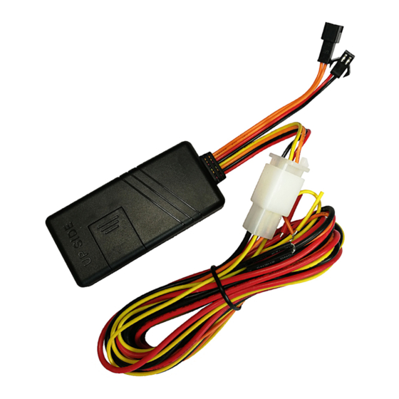
- Page 1 ——— GPS Tracker —— For Vehicle <GPS+GSM+SMS/GPRS>S User Manual V1.0 Model:TK116 ---------Appearance--------- - 1 -...
- Page 2 Using TK116 GPS tracker, we can position 、 monitor and control the vehicle on the position server via GPRS、GPS and Internet. It can help...
-
Page 3: Table Of Contents
Catalog 一、Product Features ..... 1 二、Components and Accessories . 2 三、Environment for use ....3 四、Technical Specifications ..4 五、Installation ......5 5.1Before Installation....5 5.2 Install the terminal .... 9 5.3 Terminal wiring definition ........... 11 5.4 Terminal wiring diagram..13 六、Attentions for wiring .. - Page 4 8.4 Monitor ......18 8.5 Cut off the fuel pump connection......18 8.6 Recover the fuel circuits19 九、Login the position server . 19 十、Trouble shooting ....19 10.1 Cannot connect to the position server ......19 10.2 Show offline status on the position server....
-
Page 5: 一、Product Features
一、Product Features ■ Supports quad bands, i.e. 850/900/1800/1900MHz, universal in the world. ■Wide Input Voltage:6-36V DC. ■ Supports single positioning and feedbacks position via GPRS at setting times. ■Supports vehicle positioning and tracking. ■Supports ACC status checking and vehicle status notifying. -
Page 6: 二、Components And Accessories
二、 Components and Accessories ■ Components -Top Front- -Top Back- - 2 -... -
Page 7: 三、Environment For Use
■ Accessories(reference pictures) Power Cables(Fault) MIC(Optional) Relay ( Optional) SOS Cables ( Optional) 三、Environment for use 1、 Limited working temperature:-20℃~80℃ 2、 Storage temperature:-45℃~90℃ 3、 Humidity:<95% 4、 Atmospheric pressure:86kPa~106kPa 5、 Make sure the terminal is installed in rainproof and snow-proof places. - 3 -... -
Page 8: 四、Technical Specifications
四、Technical Specifications ■Basic Specifications: Voltage 12VDC/24VDC Standby Current <3mA Work current <30mA positioning accuracy positioning 100m accuracy GPS Frequency 1575MHz GSM Frequency 850/900/1800/1900MHz <3s,<15s,<60s Hot/warm/cold start time : L*W*H Dimensions (mm) 79.5X38.5X10.5 Weight 45 g ■ LED Indicators Blue LED/GPS Red LED/GSM - 4 -... -
Page 9: 五、Installation
1、Red LED(indicates GSM working state) 0.2s on and o.2s off Searching (fast flicker) network 0.2s GSM/GPRS works (intermittently flicker) normally 2、Blue LED(indicates GPS signal state) 0.2s on and o.2s off Searching (fast flicker) Satellites 0.2s GPS works normally (intermittently flicker) 五、Installation 5.1Before Installation 5.1.1 Open the packing case, then check if the... - Page 10 ●Pull down the SIM cover(three steps) - 6 -...
- Page 11 ●Install SIM Card(two steps) First、 Insert the SIM card until cannot move it inside anymore; Second、Pull the SIM card back a bit; - 7 -...
- Page 12 ●Uninstall the SIM card First、Lift up the edge of the SIM card; Second、Pull out the SIM card. 5.1.4 Notice ●Please cut off the power before installing or uninstalling the SIM card. ●The SIM card should support GPRS and the GPRS should be opening. ●Inquiry by call needs the SIM card supporting the calling line identification presentation.
-
Page 13: Install The Terminal
● Please make sure that the SIM card has sufficient balance. 5.2 Install the terminal 5.2.1 Suggest to install the terminal concealed by the dealer designated professional body. Please make sure to install the terminal with this side upward, and use wide strong double-sided adhesive sponge to fix it. - Page 14 order to avoid damages. ● Keep the terminal away from RF emission sources such as backing radar、car burglar alarm and other vehicle mounted communication devices. ● Suggest to use wide strong double-sided adhesive sponge to fix it, or use cable ties and other liable methods to fix it.
-
Page 15: Terminal Wiring Definition
5.3 Terminal wiring definition - 11 -... - Page 16 5.3.1 Power cables and other interface for remote control - 12 -...
-
Page 17: Terminal Wiring Diagram
5.3.2 Other accessories’ interfaces 5.4 Terminal wiring diagram Relay wiring diagram shows how to wire the relay to control the fuel pump: 5.4.1 Connect the 85 terminal(with small white cable) to the positive pole of the vehicle power(+12V/+24V), connect the 86 terminal(with small yellow cable) to the 4# cable of the terminal. - Page 18 cable), showing as in the figure. Notice: Be sure that the voltage of the vehicle power should match up to the working voltage of the relay, or the relay will be damaged. Relay Wiring: Bottom of the relay - 14 -...
- Page 19 -Wiring Diagram - 15 -...
-
Page 20: 六、Attentions For Wiring
六、Attentions for wiring 6.1 Power cables 6.1.1The standard input voltage of the terminal is 6V-36VD, so please choose the our original power cables, the red cable is positive and the black cable is negative; Please ground the positive pole separately or ground it to ground connection, not to any other ground. -
Page 21: 七、Set Up The Terminal
七、Set up the terminal Please refer to the 《 Operation Commands》 八、Use the terminal 8.1 Power on Power on: insert a valid SIM card and wire all the cables, then the terminal power on itself. 8.2 LED indicators The red LED flickers fast when the terminal is searching network, flickers... -
Page 22: Sos Alarm
Customer can login the position server to check the position of the vehicle. Please ask your dealer for the WWW address of the position server. 8.3 SOS alarm Press the SOS button for 3 seconds when an emergency situation need help, SOS alarm will be triggered. -
Page 23: 九、Login The Position Server
safety, and the vehicle will not be powered on. To make sure the safety of the vehicle, the fuel of the vehicle will be cut off only if the terminal has positioned by GPS and the speed of the vehicle is less than 20KM/h or the vehicle is not moving. -
Page 24: Show Offline Status On The Position Server
server when installed at the first time. Please check the terminal: 1)If the power cables are wired correctly? Pay attention to not connect them to the controlling cables of the vehicle. 2) If the SIM card is installed correctly? Please refer to the installation instructions. -
Page 25: Cannot Position For A
5)If the terminal becomes offline on the last day of one month, please check if GPRS is close. 6) Inquiry the parameters of terminal via commands and check the accuracy of the parameters. 10.3 Cannot position for a long time If the GPS is active, but the terminal cannot be positioned for long time, please check the terminal:... -
Page 26: Instructions Receiving
10.5 Instructions receiving abnormally 1)Check the instructions format. 2)Check if the vehicle is in the places where there is GSM signal. 3)Check if the SIM card is properly installed. 十一、Warranty rules 11.1 Special statement 1)Technology change, without notice. 2) If the color and appearance are inconsistent with those for the actual product, the latter will prevail. - Page 27 11.3 After sales Any of the following circumstances not covered by the warranty, but may be appropriate to pay repair: (一)More than the warranty period. (二)Unauthorized removal or repair damaged. ( 三 ) Damage caused by improper installation, use, maintenance, custody.
-
Page 28: Customer's Information
Customer’s Information Name: Tel: Add: Product Model: IMEI Number: Selling Unit: Purchase Date: - 24 -... - Page 29 - 25 -...
Need help?
Do you have a question about the TK116 and is the answer not in the manual?
Questions and answers