Table of Contents
Advertisement
TECHNICAL OPERATION HANDBOOK
ADVENT FLYDRIVE 120-150 ANTENNA
The Document is supplied on the express terms that it is to be
treated as confidential and that it may not be copied, used or
disclosed to others for any purpose except as authorised by
ADVENT COMMUNICATIONS
Vislink House
27 Maylands Avenue
Hemel Hempstead
Hertfordshire
HP2 7DE
England
Telephone:
Fax:
24 Hour Support
Email
Advent Communications is a brand name of Vislink International
Document No. 209293 Rev. A
National
01442 431 300
01442 431 301
+44 (0)1442 431 410
UKsupport@vislink.com
For
Vislink.
Advertisement
Table of Contents

Related Manuals for Vislink AFD120 X


Summary of Contents for Vislink AFD120 X
- Page 1 ADVENT COMMUNICATIONS Vislink House 27 Maylands Avenue Hemel Hempstead Hertfordshire HP2 7DE England Telephone: National 01442 431 300 Fax: 01442 431 301 24 Hour Support +44 (0)1442 431 410 Email UKsupport@vislink.com Advent Communications is a brand name of Vislink International...
- Page 2 VISLINK This page left intentionally blank Flydrive 120-150 Antenna...
-
Page 3: Table Of Contents
VISLINK CONTENTS AMENDMENT RECORD SHEET EMC DECLARATION WARNINGS AND HAZARDS ADDITIONAL SAFETY INFORMATION STOWAGE WARNING ANTENNA 1.1 INTRODUCTION 5 SPECIFICATION 2.1 6 2.2 DRIVE CONTROL UNIT 7 2.3 MECHANICAL 8 2.4 ... - Page 4 VISLINK This page left intentionally blank Flydrive 120-150 Antenna...
-
Page 5: Amendment Record Sheet
VISLINK AMENDMENT RECORD SHEET DATE DESCRIPTION OF CHANGE AUTHOR 02/2007 03/2007 Add assembly images. 07/2007 Add Flydrive 150 details. 08/2008 Add 150 petal assembly order. 09/2008 Revised elevation limit. 07/2009 Add DC brake input details, change first aid notes. 09/2009 Page 41 added. -
Page 6: Emc Declaration
VISLINK EMC DECLARATION Flydrive 120-150 Antenna... -
Page 7: Warnings And Hazards
VISLINK WARNINGS AND HAZARDS FAILURE TO OPERATE AND USE THE EQUIPMENT OTHER THAN INSTRUCTED IN THE MANUAL MAY RESULT IN ELECTRIC SHOCK. HAZARDOUS WARNING LABELS Hazardous AC voltages present NON-IONISING RADIATION Possible source of radiation hazard, normally located at waveguide connections, waveguide joints and antennas. -
Page 8: Additional Safety Information
VISLINK ADDITIONAL SAFETY INFORMATION Most of the microwave energy is contained within this beam Close Up View Far View The European Standard that defines power levels is ETS300327. The microwave power density limit is 10w/m sq. For a 125w amplifier and 1.2m antenna, the shaded area represents power levels above the limit. -
Page 9: Antenna
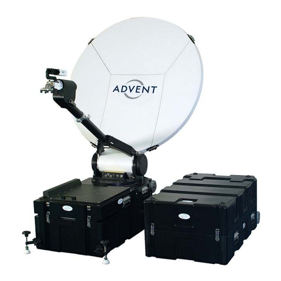
VISLINK ANTENNA INTRODUCTION The Flydrive Motorised Antenna System is a highly compact satellite earth terminal, capable of operating with most of the geostationary C, X, Ku, DBS and Ka band satellites, which are currently in orbit or are planned. Its function is to transmit TV programming and communications and to be capable of monitoring its own transmissions from many sites around the world. -
Page 10: Specification
VISLINK SPECIFICATION Type Segmented circular Diameter 1.2m or 1.5m Configuration Offset Mount Elevation over Azimuth Frequency C-Band 5.85-6.650 or 6.725-7.025 GHz X-Band 7.9-8.4 GHz Ku-Band 13.75-14.50 GHz or 12.75-13.25 GHz DBS-Band 17.3-18.1 GHz (optional 18.4GHz) Ka-Band 27.5-30.0 GHz or 30.0 to 31.0 GHz C-Band 3.7-4.2 or 4.5-4.8 GHz... -
Page 11: Drive Control Unit
VISLINK VSWR 1.2:1 1.3:1 1.4:1 1.35:1 1.2:1 1.3:1 1.3:1 1.5:1 1.3:1 1.3:1 Port/Port isolation TX/RX: 40 dB (110dB incl filter) RX/TX 30 dB TX/RX 20 dB (100dB incl filter) Rx/Tx 20 dB TX/RX 40 dB (110dB incl filter) Rx/Tx 30 dB... -
Page 12: Mechanical
VISLINK MECHANICAL Azimuth adjustment ± 200° Elevation adjustment 6° to 92° Pol. Adjustment ± 95° Motorisation Azimuth Elevation Polarisation 1.2m 1.5m Speeds 4.0°/s max. 4.0°/s max. Azimuth 2.0°/s max. 2.0°/s max. Elevation 10.0°/s max. 10.0°/s max. Polarisation Dimensions Main antenna case... -
Page 13: Enviromental Specification
VISLINK ENVIROMENTAL SPECIFICATION The system will be used outdoors, exposed to the prevailing ambient conditions. Temperature Operational -20 to +50°C Survival -40 to +70°C Humidity 0 to 100 % RH Wind Operation 20m/s Degraded Operation (roof rack configuration) 25m/s Degraded Operation (flyaway configuration) -
Page 14: Operating Procedure
VISLINK OPERATING PROCEDURE See Section 5 for the relevant assembly images. ANTENNA ASSEMBLY – FLYAWAY CONFIGURATION Open up the main antenna case. If the antenna was stowed in its sub 32kg configuration (see section 3.4), remove the four elevation arm fasteners from the main azimuth base. If the antenna was stowed in its quick deployment configuration then go to the 6th bullet point. - Page 15 VISLINK Ensure that the polarisation drive is in its stowed position by looking at the polarisation scale. If it is not in it’s stow position then rotate the feed to it’s stow position by pushing the LNB to move the back section of the feedhorn. Select the stow command from the front panel of the ACU.
-
Page 16: Antenna Assembly - Roof Rack Mount Configuration
VISLINK ANTENNA ASSEMBLY – ROOF RACK MOUNT CONFIGURATION Warning: The antenna should be fitted with the reflector facing the rear of the vehicle to reduce wind loads during transit and protect the feedhorn assembly. All fasteners and fitting that hold the antenna onto the vehicle and hold parts of the antenna together should be checked before every journey. -
Page 17: Manual Operation
VISLINK lift the amplifier onto the roof rack next to the antenna base. Fasten the inner HPA mounting bracket onto the main antenna base. Fasten the outer clamp around the roof bar. Fit the cross site waveguide between the HPA and feedarm base waveguide interface. -
Page 18: Antenna Stow Configurations
VISLINK ANTENNA STOW CONFIGURATIONS The antenna may be stowed in its cases in one of two configurations. The first configuration keeps the cases below the 32kg IATA requirement for air travel, but requires more setup time. The second quick deployment configuration allows the antenna to be assembled in less time but results in one case that exceeds 32kg. - Page 19 VISLINK MAIN ANTENNA CASE FLYDRIVE 120 QUICK DEPLOYMENT SUB 32Kg SEGMENT CASE FLYDRIVE 120 QUICK DEPLOYMENT SUB 32Kg ACCESSORY CASE Flydrive 120-150 Antenna...
- Page 20 VISLINK Flydrive 150 sub 32kg configuration Main antenna case contents: Antenna base Upper feedarm Feedhorn cartridge Segment case contents: Lower:- Reflector centre top section Reflector left top section Reflector right top section Upper:- Reflector left bottom section Reflector right bottom section Feedarm flex/twist waveguide (1.3m)
- Page 21 VISLINK Upper feedarm Feedhorn cartridge Upper:-Cross site waveguide (1.1m) AC power cable Rx L band cable MAIN ANTENNA CASE FLYDRIVE 150 QUICK DEPLOYMENT SUB 32Kg SMALL SEGMENT CASE LOWER FLYDRIVE 150 QUICK DEPLOYMENT SUB 32Kg SMALL SEGMENT CASE UPPER FLYDRIVE 150...
-
Page 22: Offset Satellite Adjustment
VISLINK OFFSET SATELLITE ADJUSTMENT If a satellite is rotated by 45 degrees in polarisation then a modification is needed to the feedhorn cartridge to improve the cross polar performance of the antenna. This currently only applies to some OPTUS satellites and Advent Communications should be consulted if clarification is needed. -
Page 23: Flydrive Maintenance
VISLINK FLYDRIVE MAINTENANCE The following maintenance is to be carried out every 3 months during normal service. If the equipment is in heavy use in extreme environmental conditions, then the maintenance period should be reduced. WARNING: - Before carrying out any maintenance, ensure that power is disconnected from the system. -
Page 24: All Screws/Bolts
VISLINK ALL SCREWS/BOLTS Check that all screws/bolts are tight. Use the following torque settings for different size screws: Screw/bolt size Torque setting (Nm) 13.8 27.1 46.7 RADIATION CHECK Perform a radiation check around the antenna, outside of the main beam. As a guidance, for transmit power of 300 watts the power density will not exceed 10mW/cm sq. -
Page 25: Assembly Images
VISLINK ASSEMBLY IMAGES Figure 5.1.1.a Figure 5.1.1.b Figure 5.1.2 Figure 5.1.3.a Figure 5.1.3.b Figure 5.1.5. Flydrive 120-150 Antenna... - Page 26 VISLINK Figure 5.1.6.a Figure 5.1.6.b Figure 5.1.7 Figure 5.1.8.a Figure 5.1.8.b Figure 5.1.8.c Flydrive 120-150 Antenna...
- Page 27 VISLINK Figure 5.1.9.a Figure 5.1.9.b Figure 5.1.10. Figure 5.1.11 Figure 5.1.12.a Figure 5.1.12.b Flydrive 120-150 Antenna...
- Page 28 VISLINK Figure 5.1.13 Figure 5.1.14 Figure 5.1.15.a Figure 5.1.15.b Figure 5.1.15.c Figure 5.1.16.a Flydrive 120-150 Antenna...
- Page 29 VISLINK Figure 5.1.16.b Figure 5.1.16.c Figure 5.1.16.d Figure 5.1.18 Figure 5.2.3 Figure 5.2.4.a Flydrive 120-150 Antenna...
- Page 30 VISLINK Figure 5.2.4.b Figure 5.2.4.c Figure 5.2.4.d Figure 5.2.7. Figure 5.2.8. Figure 5.2.9. Flydrive 120-150 Antenna...
- Page 31 VISLINK Figure 5.2.10 Figure 5.2.11 Figure 5.2.12.a Figure 5.2.12.b Figure 5.2.14.a Figure 5.2.14.b Flydrive 120-150 Antenna...
- Page 32 VISLINK Figure 5.3.1.a. Figure 5.3.1.b Figure 5.3.2.a Figure 5.3.2.b Figure 5.3.2.c Figure 5.3.3 Flydrive 120-150 Antenna...
- Page 33 VISLINK Figure 5.4.1.a Figure 5.4.1.b Figure 5.4.2.a Figure 5.4.2.b Figure 5.4.3.a Figure 5.4.3.b Flydrive 120-150 Antenna...
- Page 34 VISLINK Figure 5.4.3.c Figure 5.4.3.d Figure 5.4.3.e Figure 5.4.4.a Figure 5.4.4.b Figure 5.4.4.c Flydrive 120-150 Antenna...
- Page 35 VISLINK Figure 5.5.a Figure 5.5.b Figure 5.5.c Flydrive 120-150 Antenna...
-
Page 36: Warranty
All claims under warranty must be made promptly after occurrence of circumstances giving rise to the claim and must be received within the applicable warranty period by Vislink or its authorised representative. Vislink reserves the right to reject any warranty claim not promptly reported. -
Page 37: Transportation And Packaging
Any Product returned for examination must be sent prepaid via the means of transportation indicated as acceptable by Vislink. Vislink reserves the right to reject any warranty claim on any item that has been altered or has been shipped by non-acceptable means of transportation. -
Page 38: Figures
VISLINK 7. FIGURES FIGURE 1 – FLYDRIVE 120 CONFIGURATION – 402693 FIGURE 2 – FLYDRIVE 120 ROOF RACK MOUNT CONFIGURATION – 402692 Flydrive 120-150 Antenna... -
Page 39: Figure 3 – Flydrive 120 Petal Case In Sub 32 Kg Configurations – 402690
VISLINK FIGURE 3 – FLYDRIVE 120 PETAL CASE IN SUB 32 KG CONFIGURATIONS – 402690 Flydrive 120-150 Antenna... -
Page 40: Figure 4 – Flydrive 150 Flyaway Configuration - 403080
VISLINK FIGURE 4 – FLYDRIVE 150 FLYAWAY CONFIGURATION - 403080 FIGURE 5 – FLYDRIVE 150 ROOF RACK MOUNT CONFIGURATION - 403080 Flydrive 120-150 Antenna... -
Page 41: Figure 6 – Flydrive 150 Petal Case In Sub 32 Kg Configurations 402691
VISLINK FIGURE 6 – FLYDRIVE 150 PETAL CASE IN SUB 32 KG CONFIGURATIONS 402691 FIGURE 7 – FLYDRIVE 150 ANTENNA STOWED - 403080 Flydrive 120-150 Antenna... -
Page 42: Figure 8 – Satellite Geometry
VISLINK FIGURE 8 – SATELLITE GEOMETRY Flydrive 120-150 Antenna...
Need help?
Do you have a question about the AFD120 X and is the answer not in the manual?
Questions and answers