Table of Contents
Advertisement
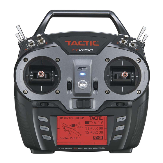
2.4GHz 8-CHANNEL
COMPUTER RADIO
INSTRUCTION MANUAL
Tactic's TTX850 computer transmitter uses
the advanced 2.4GHz spread spectrum SLT
"Secure Link Technology" protocol for solid,
interference-free control of R/C models. A
large backlit LCD, wired and wireless trainer
systems, 30 model memories, plus advanced
programming options are just a few of the
benefits which can be used for models of all
sizes. Tactic 2.4GHz transmitters are compat-
ible only with Tactic brand receivers and
those utilizing the SLT protocol.
For safe operation and
best results, it's strongly
recommended
this manual in its entirety before
use! Also read and understand the
instructions included with the model.
Damage resulting from misuse or
modification will void your warranty.
TM
™
to
read
Advertisement
Table of Contents

Subscribe to Our Youtube Channel
Related Manuals for SLT Tactic TTX850

Summary of Contents for SLT Tactic TTX850
- Page 1 2.4GHz 8-CHANNEL COMPUTER RADIO INSTRUCTION MANUAL Tactic’s TTX850 computer transmitter uses the advanced 2.4GHz spread spectrum SLT “Secure Link Technology” protocol for solid, interference-free control of R/C models. A large backlit LCD, wired and wireless trainer systems, 30 model memories, plus advanced...
-
Page 2: Table Of Contents
TABLE OF CONTENTS SLT TECHNOLOGY, Tx-R, AND Aileron Differential ....16 COMPATIBLE RECEIVERS ... . . 3 Flap Mixer . -
Page 3: Slt Technology, Tx-R, And Compatible Receivers
The TTX850 is also compatible with non-Tactic brand receivers which use the *SLT protocol, for the ultimate in convenience and fl exibility. * Make sure optional receivers have the genuine SLT protocol before use with the TTX850. -
Page 4: Ttx850 Power System
TTX850 POWER SYSTEM INPUT POWER One assembled 4.8V 1000mAh nickel-metal hydride (NiMH) battery pack is included. Optional 1.2V NiCd or 1.5V alkaline batteries can be used with an optional 4-cell fl at battery holder with universal connector. Do not mix cell types, or old and new cells, etc. Battery voltage is shown on the LCD’s home screen for easy monitoring. -
Page 5: Gimbal Sticks
receiver (mixes, exponential, etc.). Some electronic functions can be turned on/off by the pilot during fl ight such as a timer. Other functions can only be altered while the model is on the ground, such as changing travel limits or reversing for a particular channel. For multi-rotors, sideways movement of the aileron control (right stick for radios set on mode 2) controls right / left movement. -
Page 6: Digital Stick Trims
STICK TENSION: Silver screws on the Right stick, back of each gimbal are used to adjust the up/down stick tension. Turn the screw clockwise to tension make stick tension more fi rm. Turn the adjustment screw counter-clockwise to make stick tension more light. -
Page 7: Lcd, Programming Controls, Menu Navigation
LCD, PROGRAMMING CONTROLS, MENU NAVIGATION HOME SCREEN LCD contrast and backlight intensity are adjustable for optimum viewing. Six pushbuttons navigate the menus and settings. Single button pushes will result in a single incremental adjustment on-screen. Holding a button for a short time will result in slow scrolling of adjustments; continued holding will result in fast adjustments. -
Page 8: User Name
USER NAME Enter your name to identify the radio. The cursor will be under the fi rst character. Press ENTER to highlight this character. Press to fi nd the desired character, then ENTER to confi rm. The cursor will automatically move to the next cursor. Repeat as necessary for up to 11 characters. Pressing CLEAR will move the cursor back one space and erase the character in that space. -
Page 9: Model Management
Changing the model memory is not possible if the Tx battery voltage is too low. See the INPUT POWER section on page 4. It’s a good idea to keep a record of all settings in each memory as a backup in case parameters in a particular memory are accidentally changed, etc. - Page 10 Normal: One servo each is used for aileron(s), elevator(s), and rudder. V-tail: Elevator and rudder channels are mixed. Two servos are used in the tail – one for each control surface, with connections as shown in the graphic below. V-tail mixing controls the airplane’s “pitch” and “yaw”...
-
Page 11: Channel Assignments
2AI & Normal 2AI & V-tail 2AI & Delta 2AI & 2 Elev CH 1 Aileron 1 CH 1 Aileron 1 CH 1 Ailevator 1 CH 1 Aileron 1 CH 2 Elevator CH 2 V- tail 1 CH 2 Ailevator 2 CH 2 Elevator 1 CH 3... -
Page 12: Warnings
WARNINGS Warnings can be set to alert you of undesireable switch or throttle positions when the radio power switch is fi rst turned on. For example, if the throttle is at full when the radio is turned on you would see and hear an alarm. -
Page 13: Dual-Rates, Exponential
Sub-trim: Finely adjusts a channel’s center position. Be aware that extreme adjustments of sub-trim could possibly result in servo binding if the servo’s output arm moves too far in the model. This is available for all channels. DUAL-RATES, EXPONENTIAL For setting dual-rates and/or exponential travel for the Dual Rate, Exponential aileron, elevator, and rudder channels. -
Page 14: Throttle Curve
The display will show a graphic representing the switch, and the different control positions of the switch as shown here (0, 1, and 2 if applicable). The default position for “0” will always be in the up direction. The control positions of the switch can be assigned to fi t personal preference. To use the default settings, simply press ESC to confi... -
Page 15: Throttle Cut
Repeat these steps to set additional points on the graph as desired. A point for “H” is not marked on the graph, but is the right-most end of the curve line. The vertical position of this point can be adjusted by moving the cursor to the RATE percentage, pressing ENTER, then buttons. -
Page 16: Aileron Mixer
AILERON MIXER The aileron channel can be mixed to the rudder channel, which can be useful with certain wing/airplane types. To make this AILE RUDD mix active at all times do NOT assign a switch at the CTRL line. Adjust the mixture percentage and press ENTER. -
Page 17: Air Brake Set
2AI1FL: If this wing type was set, the fl ap channel can be mixed with the aileron, elevator, or back to the fl ap. Set the mix percent for each channel to be mixed, for all switch positions that control the mix. Do NOT assign a switch at the CTRL line to make the mix active at all times. -
Page 18: Camera Gimbal
Functions in this screen can support the use of miscellaneous accessories in the model, and can range from video, still camera, LEDs, etc. More than one accessory could be controlled simultaneously, and manipulated by the pilot through just one channel on the TTX850. This function requires special SLT receivers (see those instruction manuals for details). -
Page 19: Model Setup Menu - Helicopters
MODEL SETUP MENU – HELICOPTERS This menu is for setting control functions for use with helicopters. See the MODEL SETUP MENU – AIRPLANES section for functional descriptions of most menus. A swashplate type selection function is included for helicopters. With the model type set to helicopters, press ENTER for 2 seconds to access this menu from the home screen. -
Page 20: Throttle Hold
Position 1 = normal: Used for startup, take-off, landing, and typical fl ight profi les. Position 2 = idle-up 1: Used for aerobatic fl ight Position 3 = idle-up 2: Typically used as a secondary setup for aerobatic fl ight. Make sure all mechanical linkages are connected exactly as specifi... -
Page 21: Swashplate Mixer
SWASHPLATE MIXER This mix is not available when using the “1 Servo” swash setting. This function adjusts the mixture rate of the pitch, aileron, and elevator channels for the swash plate. Move the cursor to the value to adjust, and change as necessary. -
Page 22: Wireless Trainer
all channels can be set to move to a specifi c position – or only throttle channel 3 can be custom set (with all other channels holding). If using the Tactic TR825 receiver, beware that ALL channels can be set to specifi... - Page 23 OFF position. This will terminate the wireless link between both transmitters. Teacher’s radio Tactic TTX404, 410, 600, 610 – Student’s radio Tactic TTX850 1. Link the teacher’s Tx to the Rx. Remove power from the model, and then turn the teacher’s Tx off.
-
Page 24: Wired Trainer
WIRED TRAINER The TTX850 can be connected by cable to most R/C transmitters which also have a trainer / DSC jack for training purposes. See the ACCESSORIES section for details about optional trainer cords. Select the proper cord for Tactic and the other radio to be used for training purposes. 1. -
Page 25: Warning Indications
WARNING INDICATIONS The following indications will sound and/or show if any of the following occur: LOW BATTERY: Battery voltage is at or below the BATT. ALARM setting. Cannot change memories at this time. Replace or re-charge batteries. RF ON / OFF?: Turn the radio’s Rf signal on or off. THRO POS.: The throttle stick is >25% full defl... -
Page 26: Flying The Aircraft
7. Perform a range check as explained on page 24. 8. Anytime power is to be removed from the radio system, it’s important to shut down power in the aircraft fi rst. Otherwise, the aircraft could become out of control and cause a safety hazard! Move the throttle stick and throttle trim to minimum position to stop the glow engine or shut down the ESC. -
Page 27: Ttx850 Specifications
® Charge Jack: Futaba compatible Trainer System: wireless - Tactic SLT compatible, and wired TROUBLESHOOTING RANGE IS SHORT: Interference – check Rx installation and servo connections. Low Tx or Rx battery – replace the batteries or recharge if applicable. Rx may need to be located to a different position in the model for better reception. -
Page 28: Safety Guide
Practice good safety precautions at all times when fl ying model aircraft. The AMA can assist in locating authorized local fl ying clubs and fi elds. The Tactic TTX850 transmitter is intended for use with radio control model hobby airplanes and helicopters. Use with non-hobby related products for non-hobby related activities is not recommended or encouraged. -
Page 29: Fcc Statement
DTXP4704 Onyx “AA” Alkaline Battery (4) DTXP4708 Onyx “AA” Alkaline Battery (8) TACM1000 Tactic to Tactic Trainer Cord ® ® TACM1005 Tactic to Spektrum TACM1010 Tactic to Futaba ® Round TACM1011 Tactic to Futaba Square TACM1100 4.8V 1000mAh NiMH TTX850 TACP0100 TC100 AC Global Charger TACP0101 Tx Rx Charge Leads Tactic See www.tacticrc.com for a full list of radio parts and accessories. -
Page 30: Ce Compliance Information For The European Union
Declaration of Conformity: Product: Tactic TTX850 2.4GHz 8-Channel Tx and TR825 Rx Item number: TACJ2850 The objects of the declaration described here are in conformity with the requirements of the specifi cations... - Page 31 In the European Union, send it postpaid and insured to: Service Abteilung Revell GmbH Tel: 01805-110111 (nur für Deutschland) Henschelstrasse 20-30 E-mail: Hobbico-Service@Revell.de 32257 Bünde Germany Tacticrc.com Tx-Ready.com Distributed in the EU by Revell GmbH, Bünde Germany ● This product is suitable only for people of 14 years and older. This is not a toy! ●...
- Page 32 © 2014 Tactic, a Hobbico company Made in China TACJ2850 v1.0...
Need help?
Do you have a question about the Tactic TTX850 and is the answer not in the manual?
Questions and answers