Table of Contents
Advertisement
PRODUCT LITERATURE
Lennox Industries Inc.
Dallas, Texas
Tested For 50 psi.
ASME
Working Pressure
INSTALLATION
INSTRUCTIONS
COWB3
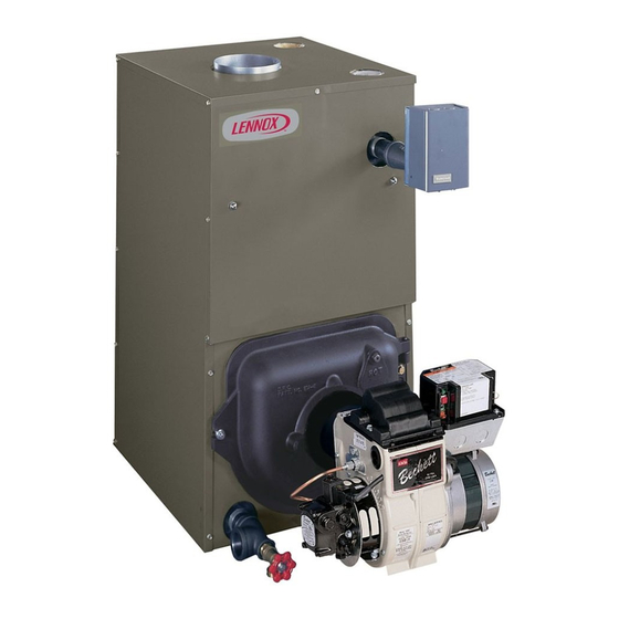
OIL FIRED BOILER
RETAIN THESE INSTRUCTIONS FOR
FUTURE REFERENCE
These instructions must be affixed on
or adjacent to the boiler.
!
WARNING
Improper installation, adjustment, alteration,
service, or maintenance could result in death
or serious injury. Refer to this manual for
assistance. For additional information consult
a qualified installer, service agency, or the oil
supplier.
OIL FIRED BOILERS
These boilers are low pressure, sectional cast iron boilers
constructed and hydrostatically tested for a maximum
working pressure of psi in accordance with A.S.M.E.
(American society of Mechanical Engineers) Section IV
Standards for cast iron heating boilers.
P/N 240009550, Rev. E [12/2014]
Advertisement
Table of Contents

Related Manuals for Lennox COWB3


Summary of Contents for Lennox COWB3
- Page 1 INSTALLATION INSTRUCTIONS PRODUCT LITERATURE Lennox Industries Inc. COWB3 Dallas, Texas OIL FIRED BOILER RETAIN THESE INSTRUCTIONS FOR FUTURE REFERENCE These instructions must be affixed on or adjacent to the boiler. WARNING Improper installation, adjustment, alteration, service, or maintenance could result in death or serious injury.
-
Page 2: Table Of Contents
SAFETY NOTICES Safety Notices ............. 2 Introduction Conservator 2 water boiler is a natural draft oil fired hot Boiler Ratings And Capacities ......3 water boiler comprised of cast iron sections. Conservator 3 Safe Installation And Operation ......4 Water boiler is available with 3, 4, or 5 cast iron sections. These sections are held together by cast iron push nipples. -
Page 3: Boiler Ratings And Capacities
85.0 8” X 8” X 15” 17¾ 9⅝ COWB3-4-1.50 1.50 84.0 8” X 8” X 15” 17¾ 9⅝ » COWB3-5-1.20 1.20 86.5 8” X 8” X 15” 11½ COWB3-5-1.75 1.75 84.3 8” X 8” X 15” 11½ * Mbh = 1,000 BTU per hour... -
Page 4: Safe Installation And Operation
SAFE INSTALLATION AND OPERATION NOTICE WARNING This boiler has been designed for residential Burn and scald hazard. Safety relief valve could installations. If used for commercial applications, discharge steam or hot water during operation. all jurisdictional requirements must be met. This Install discharge piping per these instructions. -
Page 5: Locating The Boiler
LOCATING THE BOILER Complete Prior To Installing Boiler. Place boiler in location centralized with the piping system and as close to chimney as possible. A. Verify you have selected the right size boiler with Boiler must be level. If necessary use metal shims proper capacity. - Page 6 LOCATING THE BOILER Figure 3 - Boiler With Piping System...
-
Page 7: Fresh Air For Combustion
FRESH AIR FOR COMBUSTION EXAMPLE 2: Boiler Located in Confined Space WARNING Asphyxiation, fire hazard. Do not obstruct air All Air from Inside the Building: Confined space openings to combustion area. Follow instructions shall be provided with two permanent openings communi- below, to maintain adequate combustion air. - Page 8 FRESH AIR FOR COMBUSTION All Air from Outdoors: Confined space shall be pro- free area of one square inch per 2,000 Btu per vided with two permanent openings, one commencing hour of total input rating of all equipment in the within 12 inches of top and commencing within 12 enclosure.
-
Page 9: System Piping
SYSTEM PIPING Installation of boiler for new heating system, Low Design Water Temperature Systems (Below 140° F) And Large Water Content Systems Install all of radiation units (panels, radiators, baseboard, or tubing) and supply and return mains first. After all heating system piping and components •... - Page 10 SYSTEM PIPING Figure 7 - Bypass Piping Arrangement Diagram > LOW DESIGN WATER TEMPERATURE SYSTEMS > LARGE WATER CONTENT SYSTEMS > PIPING ARRANGED FOR “POWER PURGING” AIR OUT OF THE SYSTEM PIPING, REFER TO THIS MANUAL’S SECTION ON “FILLING THE SYSTEM WITH WATER”...
- Page 11 SYSTEM PIPING Figure 8 - System Piping Arrangement Zoning With Zone Valves > CIRCULATOR ON SUPPLY PIPING PUMPS AWAY FROM EXPANSION TANK NOTE: CIRCULATOR CAN ALSO BE INSTALLED ON RETURN PIPING. > PIPING ARRANGED FOR “POWER PURGING” AIR OUT OF SYSTEM PIPING, REFER TO THIS MANUAL’S SECTION ON “FILLING THE SYSTEM WITH WATER”...
- Page 12 SYSTEM PIPING Figure 9 - System Piping Arrangement Zoning With Circulators > CIRCULATOR ON SUPPLY PIPING PUMPS AWAY FROM EXPANSION TANK > PIPING ARRANGED FOR “POWER PURGING” AIR OUT OF SYSTEM PIPING, REFER TO THIS MANUAL’S SECTION ON “FILLING THE SYS- TEM WITH WATER”...
- Page 13 SYSTEM PIPING Figure 10 - System Piping Arrangement Alternate Near Boiler Piping > PER THIS MANUAL, USE OPTION #2 IN > DIAPHRAGM EXPANSION TANK MOUNTED “FILLING THE SYSTEM WITH WATER” OFF THE BOILER > THIS PIPING ARRANGEMENT CAN BE USED >...
- Page 14 Model (MBH) coil see figure below. Coil provides instantaneous heating Rate (gph) (gpm)‡ of water for domestic use if proper burner and water supply COWB3-3-.65 0.65 2.90 line controls are used. Tankless coils are meant to provide COWB3-3-.75 0.75 3.00 domestic hot water for intermittent draws, not continuous flow.
-
Page 15: System Piping Arrangement
SYSTEM PIPING ARRANGEMENT Antifreeze added to boilers must be nontoxic, and PIPING WATER VOLUMES must be of type specifically intended for use in closed COPPER PIPE STEEL PIPE hydronic heating systems. Under no circumstances PIPE SIZE FACTOR FACTOR should automotive antifreeze be used. Antifreeze used in any boiler may reduce capacity by 10% or more and ½”... -
Page 16: Chimney And Chimney Connections
CHIMNEY AND CHIMNEY CONNECTIONS For oil fired boilers for connections to vents or chimneys, WARNING vent installations shall be in accordance with requirements Fire Hazard. Maintain minimum vent pipe clearance of authority having jurisdiction, or in the absence of such of 18”... -
Page 17: Typical Chimney Connection
TYPICAL CHIMNEY CONNECTION Figure 12 - Typical Chimney Connection... -
Page 18: Electrical Connections
ELECTRICAL CONNECTIONS WARNING Electrical shock hazard. Turn OFF electrical power sup- ply at service panel before making electrical connections. Failure to do so could result in death or serious injury. Thermostat Install 24 Volt thermostat (not provided) in proper location. Location of thermostat has effect on boiler system operation. -
Page 19: Filling The Boiler
FILLING THE BOILER How A Hot Water System Operates OPTION #2 Entire heating system (boiler, piping, and radiation units) is filled with water. As water in the boiler is heated, it is • Close air vents on all radiation units. circulated from top of boiler through supply main to ra- •... -
Page 20: Operating The Boiler
OPERATING THE BOILER Air Supply For Combustion: Start: Fill entire system with water. Vent all air from sys- tem following section for Filling The Boiler. • Do not install boiler in rooms with insufficient air, unless corrective steps are taken. •... - Page 21 OPERATING THE BOILER Nozzles And Electrodes Oil Burner Maintenance : Use proper size, spray angle, : Perform following and spray pattern nozzle. Refer to recommended nozzle preventative maintenance annually, preferably prior to selection charts. heating season. To install nozzle, remove nozzle line electrode assembly, if necessary remove retention ring assembly, and install Fuel Filter Replace to prevent contaminated fuel from and tighten nozzle.
- Page 22 OPERATING THE BOILER Figure 13 -Burner Adjustments and Settings...
-
Page 23: Checking And Adjusting Controls
CHECKING AND ADJUSTING CONTROLS Check Thermostat Operation: WARNING Follow instructions included with your thermostat. Burn, scald hazard. Do not attempt to start the Locate thermostat five feet above the floor on inside wall. burner when excess oil has accumulated, when Locate thermostat to sense average room temperature, the unit is full of vapor, or when the combustion avoid the following:... -
Page 24: Maintenance
MAINTENANCE Annually Diaphragm Expansion Tank : Recommend flue passages, combustion cham- : Tank may become water ber area (target wall, fire door insulation, durablanket), logged. Frequent automatic opening of safety relief valve burner adjustment, control operation, and boiler seals (fire indicates water logging. -
Page 25: Oil Boiler / Burner Cleaning Instructions
OIL BOILER / BURNER CLEANING INSTRUCTIONS Oil Boiler Cleaning: Carefully vacuum soot accumulations from combus- tion chamber area, take care to not damage any of Shut off all electrical power to boiler / burner and shut refractory or blanket insulation. To gain access to off fuel oil supply. -
Page 26: Oil Burner Cleaning
OIL BURNER CLEANING These are general instructions for cleaning an oil burner. For specifics, consult burner manufac- turer’s instructions. WARNING Electrical shock hazard. Turn OFF electrical power sup- ply at service panel before making electrical connections. Failure to do so could result in death or serious injury. Verify all electrical power to boiler / burner and fuel supply to burner are shut off. -
Page 27: Service Hints
SERVICE HINTS You may avoid inconvenience and service calls by checking these points before you call for service: IF YOUR SYSTEM IS NOT HEATING OR NOT GIVING ENOUGH HEAT . . . POSSIBLE CAUSE WHAT TO DO Thermostat is not set correctly Reset thermostat Check flame. -
Page 28: Electrical Wiring
ELECTRICAL WIRING Figure 16 - Boiler Honeywell L7248L Control... - Page 29 ELECTRICAL WIRING Figure 17 - Honeywell L7248L Control With Reillo F5/F10 Burner...
- Page 30 ELECTRICAL WIRING Figure 18 - Honeywell L7248L Control Wiring with Zone Pumps and Argo ARM Switching Relay (With Tankless coil Shown)
-
Page 31: Equipment And Optional Accessories
EQUIPMENT AND OPTIONAL ACCESSORIES MAIN AIR VENT: for down flow systems or diaphragm CIRCULATOR (provided) type expansion tanks (not provided) Every forced hot water system requires circulator. Separate circulator or zone valve is required for each zone, if there Before system is filled with water, there is air in pipes and are two or more zones. - Page 32 PRODUCT LITERATURE Lennox Industries Inc. Dallas, Texas...
Need help?
Do you have a question about the COWB3 and is the answer not in the manual?
Questions and answers