Table of Contents
Advertisement
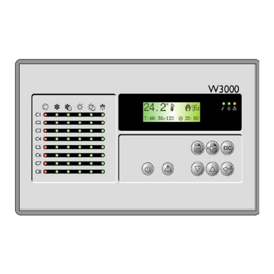
W3000
TECHNICAL MANUAL
C0240111-04-05-GB
Replaces C0240111-03-05-GB
CLIMAVENETA S.p.A
Via Sarson, 57C
36061 Bassano del Grappa(VI)-ITALY
Tel. (+39) 0424 509 500
G B
Fax. (+39) 0424 509 509
www.climaveneta.it
info@climaveneta.it
The information contained in this document may be modified without prior notice.
No part of this document may be reproduced and/or disclosed to third parties or competitors.
April 2005
Advertisement
Table of Contents

Related Manuals for CLIMAVENETA W3000


Summary of Contents for CLIMAVENETA W3000
- Page 1 W3000 TECHNICAL MANUAL C0240111-04-05-GB Replaces C0240111-03-05-GB CLIMAVENETA S.p.A Via Sarson, 57C 36061 Bassano del Grappa(VI)-ITALY Tel. (+39) 0424 509 500 Fax. (+39) 0424 509 509 www.climaveneta.it info@climaveneta.it The information contained in this document may be modified without prior notice. No part of this document may be reproduced and/or disclosed to third parties or competitors.
-
Page 2: Table Of Contents
“B” HARDWARE (for hermetic compressors)................90 EXPANSIONS ........................92 SYMBOLS ..........................105 Notice: The W3000 controller software is protected by a digital signature. This means that it can only work on cards supplied by Climaveneta and not on cards purchased from other dealers. -
Page 3: User Interface
[ALARM key]: displays the alarms and resets normal operating conditions. [SETPOINT key]: directly accesses the setpoint menu. [ON/OFF key]: switches the machine on and off. For each compressor, the following LED's are also located on the W3000 user interface: Symbol Colour Description... -
Page 4: Menu Structure
Manufacturer Manufacturer Selezione Factory Password Esc / Menù costruttore menu selection Menù costruttore costruttore Password menu Figure 2.1: menu tree for W3000-W3000 compact DISPLAY MASK Unit menu selection Unit menu Setpoint menu selection Setpoint menu Display I/O menu menu selection... - Page 5 C0240111-04-05-GB The menus are briefly described below: The “Unit Menu” contains information such as temperature, pressure and circuit states. The “Setpoint menu” is used to set the setpoints for the various available functions. The “I/O menu” shows the status of the digital inputs and values read from the analogue inputs. It also shows the status of the digital outputs and the voltage supplied to the analogue outputs.
-
Page 6: Setting The Connections
[annex 2] at the end of this manual. 3.1 Available hardware UNIT “S” Pro gramming K ey Clock card W3000 Anal o g Sele ctio n Serial Card Fuse UNIT “M”... - Page 7 C0240111-04-05-GB W3000 UNIT “XL” W3000 UNIT “B”...
- Page 8 C0240111-04-05-GB EXPANSION “E” W3000...
-
Page 9: Connecting More Than One Unit
C0240111-04-05-GB 3.2 Connecting more than one unit Caution: perform the following operations before touching the cards in order to prevent electrostatic discharge: wear the bracelet (connected to the earth circuit) and the heel strap the card should be closed inside an antistatic bag protecting it from electrostatic discharge: remove it from the bag and place it on the light-blue mat with the yellow edge or on the dark-blue mat. - Page 10 C0240111-04-05-GB Number of compressors for circuit 3 Chiller with 3 or 4 hermetic or 4 compressors per circuit EXPANSIONS FOR SEMI-HERMETIC COMPRESSORS: Additional function Function, chiller type Expansion Expansion address type Recovery enable Chiller with heat recovery Recovery enable Multi-use Heat pump with total heat recovery Freecooling enable Freecooling chiller...
- Page 11 C0240111-04-05-GB 3.2.2 “MASTER-SLAVE” CONNECTION Intelligence is distributed instead in the “master-slave” connections. Suppose we have a unit with 4 cooling circuits: t he master card manages circuits 1 and 2 while the slave card manages circuits 3 and 4 . In this case, the additional card is not simply an input/output expansion, but is fully involved managing part of the unit.
- Page 12 C0240111-04-05-GB Figure 3.3: “mixed” connection...
-
Page 13: Additional Connections
C0240111-04-05-GB 3.3 Additional connections CONFIGURING ANALOGUE INPUTS ON “S” OR “M” CARDS: On “S” or “M” cards, the analogue inputs must be configured with dipswitches. Analogue inputs B1, B2, B3 and B4 can be configured both as a temperature probe and as pressure transducers;... -
Page 14: Configuring The Terminals
The first operation to perform when a network is started up for the first time or an I/O card is replaced, is to activate the procedure for terminal configuration. This cannot be done with W3000 base. In this case, configure the terminals with a W3000 or W3000 compact terminal and then replace the display with a W3000 base. - Page 15 C0240111-04-05-GB pLan address: Set the required address (e.g.: 1 ) increase To do this, press [UP] or [DOWN]; press [ENTER] to confirm. DOWN: decrease ENTER: save & exit An “empty” mask appears because the address of the keyboard is 0 and that of the card is (for example) 1; the two devices therefore cannot communicate.
- Page 16 C0240111-04-05-GB 3.4.4 CONFIGURING THE PLAN NETWORK CONFIGURING THE PLAN NETWORK (local): For each unit with an on-board keyboard, perform the following procedure to create a “locale” plan network: Display address Press [UP], [DOWN] and [ENTER] together and hold down until Setting..:00 the mask shown to the side appears.
- Page 17 To connect several units together and remote control them, thereby forming a plan network (global), connect a remote keyboard controlling all the plans (local). The remove keyboard cannot be used with a W3000 base keyboard. If a W3000 keyboard is fitted to the unit, change it with a W3000 or W3000 compact.
- Page 18 In this case, the various machines of the network are switched by pressing [ESC] and [UP] together. If the plan network does not comprise just W3000 chillers, a 16-key keyboard must be used. In this case, press [UNIT] to switch between one card and another. In this case, however, the terminals must be given a special configuration as the 16-key keyboard is only recognised on “terminal 3”.
- Page 19 C0240111-04-05-GB Disconnect the connector J10 connecting the keyboard on the unit with the card, and connect it to connector “A” of the “T” shunt (see figure 3.5). Connect connector J10 on the card to connector “B” of the “T” shunt. The correct configuration is shown in figure 3.5: Figure 3.5 : connecting the remote keyboard (for distances less than 200 metres) 2.
- Page 20 C0240111-04-05-GB SHIELDED TWISTED Figure 3.6: connecting the remote keyboard (for distances between 200 and 500 metres)
-
Page 21: Switching The Unit On And Off
SWITCHING OFF: press the [ON-OFF] key. In the W3000, the message Com. : ON appears on the display In the W3000 base, the message “On” appears on the display with the LED on, or “OFF” with the LED off. using the On/Off parameter: Only in the W3000 and W3000 compact. - Page 22 In the W3000 base the following procedure is used: press [MENU] / select the User menu using the [UP] or [DOWN] keys / press [ENTER] to access the menu / press enter to type in the password / press [UP] or [DOWN] to choose the password and [ENTER] to confirm / use the [UP] or [DOWN] keys to choose the “SPr”...
-
Page 23: User Programming
In the W3000 base the key sequence is: switch off the unit using the [ON/OFF] key / press the [setpoint] key / select MODE with the [UP] or [DOWN] keys / press [Enter] / press [Enter]. At this point the cursor flashes. - Page 24 In the W3000 base press [ON/OFF] to switch the unit off. Access the “user menu” / press [UP] or [DOWN] to select “SV M”/ press [Enter] to view the set mode / press [Enter] to see the setting flashing / press [UP] or [DOWN] to modify the setting / press [Enter] to confirm the new setting.
-
Page 25: User Menu
C0240111-04-05-GB 5.2) USER MENU The “user menu” is used to display and set important operating, adjustment, setpoint and “recovery” parameters. The physical principles lying at the heart of some special functions are described below. 5.2.1 ) ADJUSTMENT Depending on the type of hardware and the type of compressor used, a choice may be made (for inlet or outlet temperature) between STEP and QUICK MIND adjustment. - Page 26 C0240111-04-05-GB Winter (n° steps = 2) proportional band Figure 5.2: T is the inlet variable, P is the percentage of delivered power (winter). = Set + proportional band/2 Table 5.1 and 5.2 show some typical values for the parameters in question. The theoretical maximum and minimum outlet temperature values refer to operation at nominal flow rates ( with a thermal head at the evaporator of 5 °C and sufficient water in the system to ensure a litre / KW ratio equal to or greater than 11).
- Page 27 C0240111-04-05-GB ESTATE SUMMER Compressors deactivated Compressors activated Disattivazione compressori Attivazione compressori DEAD AREA ZONA NEUTRA Tin/Tout Setpoint INVERNO WINTER Compressors activated Attivazione compressori Disattivazione compressori Compressors deactivated DEAD AREA ZONA NEUTRA Tin/Tout Setpoint Figure 5.3: QUICK MIND adjustment model (summer and winter) The setpoint remains within a dead area.
- Page 28 C0240111-04-05-GB Fase di avviamento controllato = Controlled starting phase Adattamento zona neutra = Adaptation to dead area Temperatura uscita evaporatore = Outlet temperature of evaporator Temperatura ingresso evaporatore = Inlet temperature of evaporator 1 compressore attivo = 1 compressor active 2 compressori attivi = 2 compressors active Figure 5.4: example of real data with quick-mind outlet adjustment (x-axis: time in [s];...
- Page 29 C0240111-04-05-GB ADJUSTMENT METHOD FOR CENTRIFUGE COMPRESSORS: The W3000 controller can manage units with centrifuge compressors. The units are combination-adjusted (steps and continuously), with steps for activating the compressors. Some diagrams outlining how this works are shown below. Suppose we have a single compressor unit (figure 5.5).
- Page 30 C0240111-04-05-GB s e t p o i n t T i n [ ° C ] P r o p o r t i o n a l b a n d s t a r t c o m p r e s s o r 1 s e t p o i n t t [ m i n ] O F F...
-
Page 31: Recovery
C0240111-04-05-GB S e t p o i n t T i n [ ° C ] s e t p o i n t p r o p o r t i o n a l b a n d b a n d a p r o p o r z i o n a l e s t a r t c o m p r e s s o r 2 °... - Page 32 C0240111-04-05-GB 100% Banda regolazione recupero Recovery adjustment band T.Rec [°C] Setpoint Recovery recupero setpoint Figure 5.10: recovery function of a 4-circuit unit...
-
Page 33: Setpoint Menu
“secondary setpoint” function is enabled in the “user menu”). 5.4) CLOCK MENU The clock menu is not enabled in the W3000 base. After enabling time bands from the “enable time bands” parameter in the “user menu”, time bands can be set and specific operating modes and different setpoints can be set according to requirements. -
Page 34: Manufacturer Programming
C0240111-04-05-GB MANUFACTURER PROGRAMMING The manufacturer menu is not present in the W3000 base. For the other user interfaces, instead, access the manufacturer menu by pressing [Menu] / selecting the manufacturer menu by pressing [UP] / entering the password. The tree diagram of the manufacturer menu is shown in figure 6.1. -
Page 35: Freecooling
C0240111-04-05-GB 6.1) FREECOOLING The “freecooling” function is applied to the efficient production of cold water by using external air. The operating principle is illustrated in figure 6.2. FREECOOLING EVAPORATOR COIL “3-way” valve water Figure 6.2: block diagram of the freecooling activation circuit If the external water is cold, the valve closes and the water passes through the coil which cool the water by the water-air heat exchange achieved thanks to the internal fans. -
Page 36: Condensation
C0240111-04-05-GB dem and Step speed adjustm ent n. step T. in D ynam ic Chiller Dynam ic freecooling band Setpoint Setpoint Figure 6.3c: fan adjustment in the step mode (example with 8 fans) demand Continuous speed adjustment 100% T. in Dynamic Chiller Dynamic freecooling band... - Page 37 C0240111-04-05-GB Active Step adjustment steps Step2 on Step1 on Step3 on Step4 on Set Point - Set Point Set Point Set Point Set Point Set Point - Set Point - Set Point - differential differential differential differential Pressure Figure 6.4b: “step” condensation adjustment Condensation Continuous adjustment 100%...
-
Page 38: Alarms
To reset the alarm press the [ALARM] key again and hold it down until the message “No Alarm Active” (for W3000 or W3000 compact) or “No A” (for W3000 base) appears. If the message does not appear it means that one or more alarm conditions are still active. - Page 39 Glycol pump thermal protection freecooling). Slave no-link Slave card unlinked (in units with 3 or 4 circuits). Master expansion 1 unlinked. Apart from W3000 Expansion 1 no-link base, the word master appears in units with 3 or 4 circuits. “as above, for expansion 2”...
- Page 40 C0240111-04-05-GB Compressor 7 maintenance “as above, for compressor 7” “as above, for compressor 8” Compressor 8 maintenance High pressure on cooling circuit 1 Circuit 1 high pressure “as above, for circuit 2” Circuit 2 high pressure “as above, for circuit 3” Circuit 3 high pressure “as above, for circuit 4”...
- Page 41 C0240111-04-05-GB Probe 6 error card 2 “analogue, as above” “analogue, as above” Probe 7 error card 1 “analogue, as above” Probe 7 error card 2 “analogue, as above” Probe 8 error card 1 “analogue, as above” Probe 8 error card 2 “analogue, as above”...
- Page 42 C0240111-04-05-GB Probe 3 error expansion 4 slave “analogue, as above” “analogue, as above” Probe 4 error expansion 4 slave “analogue, as above” Probe 1 error expansion 5 slave “analogue, as above” Probe 2 error expansion 5 slave “analogue, as above” Probe 3 error expansion 5 slave “analogue, as above”...
-
Page 43: Annex 1A : Table Of W3000 Masks
C0240111-04-05-GB ANNEX 1a : TABLE OF W3000 MASKS Press [UP] or [DOWN] to move from one mask to another inside the same menu. Press [ENTER] to access the parameter, press [UP] or [DOWN] to change the value of the parameter. - Page 44 C0240111-04-05-GB Access mask to user global parameters submenu. Press "Up" or "Down" to scroll Global. the other masks and "Esc" to return to the submenu. Neutral area (Only visible in the quick mind adjustment mode). Used to centre the neutral centre : 050 % zone with respect to the setpoint.
- Page 45 C0240111-04-05-GB High temp. pressure Enables setting of the pressure switch control of high temperatures by separating switch control active circuit power Enabled: High temp. pressure Enables the setpoint and differential for the pressure switch control of high switch control temperatures Setpoint: 23.5 bar Diff:...
- Page 46 C0240111-04-05-GB Power decr. impulse: Sets the period and duration of the power decrease impulse. Period: 001 s Min. dur.: 01.5 s Max. dur.: 03.0 s Compressor start Sets the start-up time of the compressor, that, is, the time the compressor time: 30 s remains in the no-load start mode before it starts adjusting.
- Page 47 C0240111-04-05-GB Compressor revs Sets the voltage and revs for converting the signal from the compressors. reading conversion 0-390mV - 0-48000rpm Access mask to valves submenu. Press "Up" or "Down" to scroll the other masks Valves and "Esc" to return to the submenu. Status configuration Status editor mask.
- Page 48 C0240111-04-05-GB Condensation control Selects between individual and contemporary condensation. Also sets linear fan operation. Type: Separate Mod.: Linear Condensation control Selects the type of valve for condensation in water-cooled chillers. Valve logic: direct Condensation control Enables pre-condensation (pre-ventilation), sets the duration and defines a value Precond.
- Page 49 C0240111-04-05-GB Direct valve Selects the type of control for the freecooling valve, direct or reverse. Also sets Fans the hysteresis of each fan and the start/stop delay for each fan. hysteresis 00.3 °C delay Access mask to defrost submenu. Press "Up" or "Down" to scroll the other Defrost masks and "Esc"...
- Page 50 C0240111-04-05-GB Low press. alarm Sets the parameters for activating the low pressure alarm. N° resets Number of times the alarm has triggered in the previous hour and been reset Start bypass 120 s automatically within the set period, the next time the alarm triggers it must be reset manually.
- Page 51 C0240111-04-05-GB Access mask to calibration submenu. Press "Up" or "Down" to scroll the other Calibration masks and "Esc" to return to the submenu. High pressure Mask for configuring the high pressure transducers. transducers Start Scale 00.0bar End Scale 30.0bar Low pressure Mask for configuring the low pressure transducers.
- Page 52 C0240111-04-05-GB Slave calibration Modifies the probe offsets. (Only present if required by the type of machine offset Value configured) 0.0°C 12.3°C 0.0°C 12.3°C Slave calibration Modifies the probe offsets. (Only present if required by the type of machine offset Value configured) 0.0°C 12.3°C...
- Page 53 C0240111-04-05-GB Hour counter Sets the threshold for programmed maintenance. Compressor 4: Threshold 010x1000 Reset N° 000000 Hour counter Sets the threshold for programmed maintenance. Compressor 5: Threshold 010x1000 Reset N° 000000 Hour counter Sets the threshold for programmed maintenance. Compressor 6: Threshold 010x1000 Reset N°...
- Page 54 C0240111-04-05-GB Temp. adjustment Sets the temperature and recovery adjustment band. band 02.5 °C Recovery adjustment band 03.0 °C Secondary setpoint Enables selection of the main or secondary setpoint via an external contact (only Enable displayed on compatible units). External setpoint Enables setpoint variation through an external input which can be configured at Enabled 4-20 mA...
- Page 55 C0240111-04-05-GB Mask showing that the clock card is missing or damaged. Clock card not installed Clock Current date and time settings. configuration: Date Time 01/01/04 08:00 Time bands Indicates that the time bands are set correctly but not enabled. To enable them, not enabled.
- Page 56 C0240111-04-05-GB An. In. master Display of analogue inputs 1 and 2. N° Value Master is only specified on units with 3 or 4 circuits. 07.3 bar 12.3 °C An. In. master Display of analogue inputs 3 and 4. N° Value Master is only specified on units with 3 or 4 circuits.
- Page 57 C0240111-04-05-GB An. In. master exp2 Displays analogue inputs 7 and 8 of expansion 2 (if present). N° Value Master is only specified on units with 3 or 4 circuits. 22.4 °C - °C Displays the state of the digital inputs of expansion 3 (if present) and specifies their state.
- Page 58 C0240111-04-05-GB An. In. slave Display of analogue inputs 3 and 4. N° Value 12.3 °C 12.3 °C An. In. slave Display of analogue inputs 5 and 6. N° Value 12.3 °C 07.3 bar An. In. slave Display of analogue inputs 7 and 8. N°...
- Page 59 C0240111-04-05-GB Displays the state of the digital outputs of expansion 3 (if present) and specifies Dig.Out. slave exp3 their state. 12345 67890 12345 C: Contact closed AAAAA AAAAA AAAAA AAAAA AAAAA AAAA O: Contact open An. In. slave exp3 Displays analogue inputs 1 and 2 of expansion 3 (if present). N°...
- Page 60 C0240111-04-05-GB Access mask to unit menu. Press "Up" or "Down" to scroll the other masks and Unit "Esc" to return to the submenu. Temp. Out. Displays inlet and outlet temperatures of the evaporator, recuperator and Evap. 12.5 07.0°C condenser (where fitted). Rec.
- Page 61 C0240111-04-05-GB Analogue outputs: Displays analogue outputs 3 and 4. Cond.3 adj.:000 % Cond.4 adj.:000 % Analogue outputs: Displays analogue outputs 5 and 6. --- % --- % Analogue outputs: 3 Displays analogue outputs 1 and 2 of expansion 3. Freecooling :000 % --- % Displays analogue outputs 1 and 2 of the slave card.
- Page 62 C0240111-04-05-GB Enable Selects/deselects compressors. compressors C1:Y C2:Y C3:Y C4:Y C5:Y C6:Y C7:Y C8:Y W 3000 This mask contains the reference information of the software [Code 07.00 ]. The closed padlock symbol shows that the card is provided with its propriety Code CA 07.00 GB software;...
-
Page 63: Annex 1B : Table Of W3000 Base Masks
C0240111-04-05-GB ANNEX 1b : TABLE OF W3000 base MASKS DISPLAY MASK Unit menu selection Unit menu Setpoint menu selection Setpoint menu Display I/O menu menu selection I/O menu Clock menu selection Clock menu User menu User selection password User menu... - Page 64 (If 2 condensers are present). The submask displays the outlet temperature of condenser 2 > > 22.4 temperature expressed in degrees centigrade The manufacturer menu is not available on this keypad >4H20 Only on the W3000 compact keypad USER User menu >REG The submask is used to set the adjustment type. >...
- Page 65 C0240111-04-05-GB > > 60 time expressed in seconds >P OF The submask is used to set the minimum pump switch-off time when the unit is switched off > > 60 time expressed in seconds >PURL The submask is used to enable power limiting >...
- Page 66 Volts SETP Setpoint menu >MODE The submask is used to set the operating mode (this depends on the machine type set in the manufacturer menu using the W3000-compact keypad) > > CH "CH"= Chiller, "HP"= heat pump >ACT The submask displays the percentage of active power of the thermoregulator >...
- Page 67 C0240111-04-05-GB > > 1 e.g.: "1"=1000 hours >LH 1 Displays compressor 1 operating hours expressed in units > > 50 e.g.: "50"=50 hours >HH 2 Displays compressor 2 operating hours expressed in thousands > > 1 e.g.: "1"=1000 hours >LH 2 Displays compressor 2 operating hours expressed in units >...
-
Page 68: Annex 1C : Parameters Table
C0240111-04-05-GB ANNEX 1c : PARAMETERS TABLE Para Description Default U.M. Min. Max. On/Off from parameter P901 Type of unit (0:chiller - 1:heat pump - 2:multi-use) P925 P902 Type of compressors (0:Centrifuge - 1:hermetic - 2:semi-hermetic - 3:screw) P903 N° circuits P904 N°... - Page 69 C0240111-04-05-GB Para Description Default U.M. Min. Max. Condenser pump enable (0:disabled - 1: enabled) Secondary circuit pump control enable for water/water units (0:disabled - 1: enabled) Flow switch alarm bypass time when starting pump on secondary circuit Flow switch alarm bypass time when stopping pump on secondary circuit Maximum acceptable continuous operating time of a pump before rotation is 1500 forced...
- Page 70 C0240111-04-05-GB Para Description Default U.M. Min. Max. P105 Off percentage for centrifuge compressor 2 P104 On percentage for centrifuge compressor 2 P107 Off percentage for centrifuge compressor 3 P106 On percentage for centrifuge compressor 3 P109 Off percentage for centrifuge compressor 4 P108 On percentage for centrifuge compressor 4 P111...
- Page 71 C0240111-04-05-GB Para Description Default U.M. Min. Max. Maximum condensation override differential in the chiller mode Enable maximum condensation override in the heat pump mode (0:No - 1:Yes) 15.0 Maximum condensation override setpoint in the heat pump mode Maximum condensation override differential in the heat pump mode 15.0 P253 Step 1 setpoint in chiller mode...
- Page 72 C0240111-04-05-GB Para Description Default U.M. Min. Max. P221 Forced defrosting pressure threshold P221 Minimum heatpump operating pressure for separating hermetic compressors P213 Restore pressure for separating the hermetic compressors Free defrost enable (0:disabled - 1:enabled) -10.0 10.0 Minimum external temperature for free defrost operation °C 28.0 P253...
- Page 73 C0240111-04-05-GB Para Description Default U.M. Min. Max. -9.9 Probe 2 expansion 1 calibration °C/bar -9.9 Probe 3 expansion 1 calibration °C/bar -9.9 Probe 4 expansion 1 calibration °C/bar -9.9 Probe 1 expansion 2 calibration °C/bar -9.9 Probe 2 expansion 2 calibration °C/bar -9.9 Probe 3 expansion 2 calibration...
- Page 74 C0240111-04-05-GB Para Description Default U.M. Min. Max. Compressor 5 hour counter threshold h x 1000 Compressor 6 hour counter threshold h x 1000 Compressor 7 hour counter threshold h x 1000 Compressor 8 hour counter threshold h x 1000 Adjustment type (0:step - 1:Quick Mind) Adjustment control type (0:inlet - 1:outlet) Start-up mode (0:standard - 1:rapid) Percentage inside the dead area in which the compressor is not modulated...
- Page 75 C0240111-04-05-GB Para Description Default U.M. Min. Max. P918 Monday time bands (0:not used - 1:A bands - 2:B bands) P918 Tuesday time bands (0:not used - 1:A bands - 2:B bands) P918 Wednesday time bands (0:not used - 1:A bands - 2:B bands) P918 Thursday time bands (0:not used - 1:A bands - 2:B bands) P918...
- Page 76 C0240111-04-05-GB Para Description Default U.M. Min. Max. Enable compressor 8 Maximum settable limit for configuring the machine type (depends on the type of hardware) Maximum settable limit for choosing the compressor type Maximum limit for the number of circuits (depends on the type of hardware) Maximum limit for the number of compressors (depends on the type of hardware) Maximum limit for the number of steps per compressor (depends on the type of hardware)
-
Page 77: Annex 2 : Input/Output Table
C0240111-04-05-GB ANNEX 2 : INPUT/OUTPUT TABLE “S” HARDWARE: WATER-AIR UNIT with “S” axial fans WATER-AIR UNIT with “S” centrifuge fans Digital inputs Digital inputs Circuit 1 high pressure switch ID1 Circuit 1 high pressure switch ID2 Circuit 2 high pressure switch Circuit 2 high pressure switch ID3 Circuit 1 low pressure switch ID3 Circuit 1 low pressure switch... - Page 78 C0240111-04-05-GB “S” WATER-WATER UNIT “S” EVAPORATING UNIT Digital inputs Digital inputs ID1 Circuit 1 high pressure switch ID1 Circuit 1 high pressure switch ID2 Circuit 2 high pressure switch ID2 Circuit 2 high pressure switch ID3 Circuit 1 low pressure switch ID3 Circuit 1 low pressure switch ID4 Circuit 2 low pressure switch ID4 Circuit 2 low pressure switch...
-
Page 79: M" Hardware
C0240111-04-05-GB “M” HARDWARE: WATER-AIR UNIT with “M” axial fans WATER-AIR UNIT with “M” centrifuge fans Digital inputs Digital inputs ID2 Phase sequence ID2 Phase sequence ID3 Circuit 1 low pressure switch ID3 Circuit 1 low pressure switch ID4 Circuit 2 low pressure switch ID4 Circuit 2 low pressure switch ID5 Compressor 1 thermal protection ID5 Compressor 1 thermal protection... - Page 80 C0240111-04-05-GB “M” WATER-WATER UNIT “M” EVAPORATING UNIT Digital inputs Digital inputs ID2 Phase sequence ID2 Phase sequence ID3 Circuit 1 low pressure switch ID3 Circuit 1 low pressure switch Circuit 2 low pressure switch ID4 Circuit 2 low pressure switch ID5 Compressor 1 thermal protection ID5 Compressor 1 thermal protection ID6 Compressor 2 thermal protection...
-
Page 81: L" Hardware
C0240111-04-05-GB “L” HARDWARE: a ) for hermetic compressors: WATER-AIR UNIT with “L” axial fans WATER-AIR UNIT with “L” centrifuge fans Digital inputs Digital inputs ID1 Circuit 1 low pressure switch ID1 Circuit 1 low pressure switch ID2 Compressor 1 thermal protection ID2 Compressor 1 thermal protection ID3 Compressor 2 thermal protection ID3 Compressor 2 thermal protection... - Page 82 C0240111-04-05-GB “L” WATER-WATER UNIT “L” CONDENSING UNIT Digital inputs Digital inputs ID1 Circuit 1 low pressure switch ID1 Circuit 1 low pressure switch ID2 Compressor 1 thermal protection ID2 Compressor 1 thermal protection Compressor 2 thermal protection ID3 Compressor 2 thermal protection ID4 Circuit 2 low pressure switch ID4 Circuit 2 low pressure switch ID5 Compressor 3 thermal protection...
- Page 83 C0240111-04-05-GB “L” EVAPORATING UNIT Digital inputs ID1 Circuit 1 low pressure switch ID2 Compressor 1 thermal protection ID3 Compressor 2 thermal protection ID4 Circuit 2 low pressure switch ID5 Compressor 3 thermal protection ID6 Compressor 4 thermal protection ID7 Circuit 1 fan thermal protection Circuit 2 fan thermal protection ID9 Evaporator flow switch ID10 Remote on/off...
- Page 84 C0240111-04-05-GB b ) for centrifuge compressors: WATER-AIR UNIT with “L” axial fans WATER-AIR UNIT with “L” centrifuge fans Digital inputs Digital inputs ID2 Compressor 1 thermal protection ID2 Compressor 1 thermal protection ID3 Compressor 2 thermal protection ID3 Compressor 2 thermal protection ID5 Compressor 3 thermal protection ID5 Compressor 3 thermal protection ID6 Compressor 4 thermal protection...
- Page 85 C0240111-04-05-GB “L” WATER-WATER UNIT “L” Digital inputs ID2 Compressor 1 thermal protection ID3 Compressor 2 thermal protection ID5 Compressor 3 thermal protection ID6 Compressor 4 thermal protection ID9 Evaporator flow switch ID10 Remote on/off ID11 Pump 1 thermal protection ID12 Pump 2 thermal protection ID13 Circuit 1 high pressure switch ID14 Circuit 2 high pressure switch ID15...
-
Page 86: Hl" Hardware
C0240111-04-05-GB “HL” HARDWARE: WATER-AIR UNIT with “HL” axial fans WATER-AIR UNIT with “HL” centrifuge fans Digital inputs Digital inputs ID1 Circuit 1 low pressure switch ID1 Circuit 1 low pressure switch ID2 Compressor 1 thermal protection ID2 Compressor 1 thermal protection ID3 Compressor 2 thermal protection ID3 Compressor 2 thermal protection ID4 Circuit 2 low pressure switch... - Page 87 C0240111-04-05-GB “HL” WATER-WATER UNIT “HL” CONDENSING UNIT Digital inputs Digital inputs ID1 Circuit 1 low pressure switch ID1 Circuit 1 low pressure switch ID2 Compressor 1 thermal protection ID2 Compressor 1 thermal protection ID3 Compressor 2 thermal protection ID3 Compressor 2 thermal protection ID4 Circuit 2 low pressure switch ID4 Circuit 2 low pressure switch ID5 Compressor oil 1...
- Page 88 C0240111-04-05-GB “HL” EVAPORATING UNIT Digital inputs ID1 Circuit 1 low pressure switch ID2 Compressor 1 thermal protection ID3 Compressor 2 thermal protection ID4 Circuit 2 low pressure switch ID5 Compressor oil 1 ID6 Compressor oil 2 ID7 Circuit 1 fan thermal protection ID8 Circuit 2 fan thermal protection ID9 Evaporator flow switch ID10 Remote on/off...
-
Page 89: B" Hardware (For Hermetic Compressors)
C0240111-04-05-GB “B” HARDWARE (for hermetic compressors) Water/air chiller with “B” axial fans Water/air chiller with “B” centrifuge fans Digital inputs Digital inputs ID1 Circuit 1 high pressure switch ID1 Circuit 1 high pressure switch ID2 Circuit 2 high pressure switch ID2 Circuit 2 high pressure switch ID3 Remote on/off ID3 Remote on/off... - Page 90 C0240111-04-05-GB “B” WATER-WATER UNIT Digital inputs ID1 Circuit 1 high pressure switch ID2 Circuit 2 high pressure switch ID3 Remote on/off ID4 Remote Summer/Winter ID5 Evaporator flow switch ID6 Circuit 1 low pressure switch ID7 Circuit 2 low pressure switch ID8 Compressor 1 thermal protection ID9 Compressor 2 thermal protection ID10 Pump 1 thermal protection...
- Page 91 C0240111-04-05-GB EXPANSIONS a ) for hermetic compressors “E” expansion for chiller with recovery. Expansion "E" – address 1 Digital inputs Digital inputs Recovery flow switch Recovery remote enable Analogue inputs Circuit 1 liquid temperature Circuit 2 liquid temperature Recovery inlet temperature ID10 Recovery outlet temperature ID11...
-
Page 92: Expansions
C0240111-04-05-GB “M” expansion for hermetic compressors. Air-cooled polyvalent units and heat pumps with total recovery. Expansion "M" – address 2 Digital inputs Digital inputs Recovery flow switch ID10 ID10 ID11 ID11 ID12 ID12 ID13 ID13 ID14 ID14 ID15 ID16 Analogue inputs ID17 Circuit 1 low pressure transducer ID18... - Page 93 C0240111-04-05-GB “M” expansion for hermetic compressors. Water-cooled polyvalent units and heat pumps with total recovery. Expansion "M" – address 2 Digital inputs Digital inputs Recovery flow switch Condenser flow switch Condenser pump thermal protection ID10 ID10 ID11 ID11 ID12 ID12 ID13 ID13 ID14...
- Page 94 C0240111-04-05-GB “E” expansion for hermetic compressors. Chiller with freecooling. Expansion "E" – address 3 Digital inputs Digital inputs Glycol pump thermal protection Analogue inputs Circuit 1 low pressure transducer Circuit 2 low pressure transducer Freecooling inlet temperature ID10 ID11 ID12 Digital outputs ID13 Hp relay circuit 1-1...
- Page 95 C0240111-04-05-GB “E” expansion for hermetic compressors. Units with more than 4 compressors. Expansion "E" – address 4 Digital inputs Digital inputs Compressor 5 thermal protection Compressor 6 thermal protection Compressor 7 thermal protection Compressor 8 thermal protection Analogue inputs Step 5 Step 6 Step 7 ID10...
- Page 96 C0240111-04-05-GB b ) for semi-hermetic compressors “E” expansions for chillers with heat pumps or two pumps. Expansion "E" – address 5 Digital inputs Digital inputs Remote Summer/Winter Pump 1 thermal protection Pump 2 thermal protection Analogue inputs Evap. 1 outlet water temperature Evap.
- Page 97 C0240111-04-05-GB “E” expansions for chillers with setpoint variation or secondary setpoint. Expansion "E" – address 3 Digital inputs Digital inputs Glycol pump thermal protection Dual setpoint Analogue inputs Setpoint variation (4-20mA) Recovery setpoint variation (4-20mA) Freecooling inlet temperature ID10 ID11 ID12 Digital outputs ID13...
- Page 98 C0240111-04-05-GB “E” expansions for chillers with recovery. Expansion "E" – address 1 Digital inputs Digital inputs Recovery flow switch Recovery remote enable Analogue inputs Circuit 1 liquid temperature Circuit 2 liquid temperature Recovery inlet temperature ID10 Recovery outlet temperature ID11 ID12 Digital outputs ID13...
- Page 99 C0240111-04-05-GB “M” expansion for semi-hermetic compressors. Air-cooled polyvalent units and heat pumps with total recovery. Expansion "M" – address 2 Digital inputs Digital inputs Recovery flow switch ID10 ID10 ID11 ID11 ID12 ID12 ID13 ID13 ID14 ID14 Analogue inputs Analogue inputs Evap.
- Page 100 C0240111-04-05-GB “M” expansion for semi-hermetic compressors. Water-cooled polyvalent units and heat pumps with total recovery. Expansion "M" – address 2 Digital inputs Digital inputs Recovery flow switch Condenser flow switch Condenser pump thermal protection ID10 ID10 ID11 ID11 ID12 ID12 ID13 ID13 ID14...
- Page 101 C0240111-04-05-GB “E” expansions for semi-hermetic compressors. Chiller with freecooling. Expansion "E" – address 3 Digital inputs Digital inputs Glycol pump thermal protection Dual setpoint Analogue inputs Setpoint variation (4-20mA) Recovery setpoint variation (4-20mA) Freecooling inlet temperature ID10 ID11 ID12 Digital outputs ID13 Hp relay circuit 1-1 ID14...
- Page 102 C0240111-04-05-GB “E” expansions for semi-hermetic compressors. Condensing unit or for alternative compressors. Unit with four compressors on two circuits. Expansion "E" – address 4 Digital inputs Digital inputs Compressor 3 thermal protection Compressor 4 thermal protection Compressor oil 3 Compressor oil 4 Analogue inputs Step 1 Step 2...
- Page 103 C0240111-04-05-GB b ) for centrifuge compressors: “E” expansion Chillers with setpoint variation or secondary setpoint. Expansion "E" – address 3 Digital inputs Digital inputs Dual setpoint Analogue inputs Setpoint variation (4-20mA) ID10 ID11 ID12 Digital outputs ID13 ID14 ID15 ID16 ID17 ID18 Analogue outputs...
-
Page 104: Symbols
C0240111-04-05-GB SYMBOLS The following symbols are used in the W3000 and W3000 compact masks. Symbol Description Unit/circuit off Ch nr Chiller circuit not demanded by thermoregulator Chiller circuit demanded by thermoregulator Ch+R Chiller circuit plus recovery demanded by thermoregulator Hp nr...
Need help?
Do you have a question about the W3000 and is the answer not in the manual?
Questions and answers
The compressor is blocked a compressor or circuit alarm
If the compressor is blocked or showing a circuit alarm, check the specific alarm code on the display. Depending on the code, the reset method may be:
- A (Automatic reset): The alarm will clear automatically once the issue is resolved.
- M (Manual reset): The alarm must be manually reset from the keypad after fixing the problem.
- A/M (Automatic/manual reset): The first few occurrences reset automatically; later ones require manual reset.
- S (Signal only): Informational, no reset needed.
Identify and resolve the cause, then reset the alarm if required.
This answer is automatically generated
The compressor is blocked by a compressor or circuit alarm
If the CLIMAVENETA W3000 compressor is blocked by a compressor or circuit alarm, first eliminate the condition that triggered the alarm. Then, depending on the alarm type:
- If the alarm is manual reset (M), reset it from the keypad after resolving the issue.
- If the alarm is automatic reset (A), it will reset itself once the issue is resolved.
- If marked A/M, it resets automatically for the first few events, then requires manual reset.
- For signal-only alarms (S), no reset is needed as they do not block operation.
Identify the specific alarm code to determine the reset type.
This answer is automatically generated