Table of Contents
Advertisement
G B
The information contained in this document may be modified without prior notice.
No part of this document may be reproduced and/or disclosed to third parties or competitors.
W3000
TECHNICAL MANUAL
C0240111-01-06-GB
Replaces C0240111-10-05-GB
CLIMAVENETA S.p.A
Via Sarson, 57C
36061 Bassano del Grappa(VI)-ITALY
Tel. (+39) 0424 509 500
Fax. (+39) 0424 509 509
www.climaveneta.it
HTU
info@climaveneta.it
HTU
UTH
UTH
January
2006
Advertisement
Table of Contents

Related Manuals for CLIMAVENETA W3000


Summary of Contents for CLIMAVENETA W3000
- Page 1 W3000 TECHNICAL MANUAL C0240111-01-06-GB Replaces C0240111-10-05-GB CLIMAVENETA S.p.A Via Sarson, 57C 36061 Bassano del Grappa(VI)-ITALY Tel. (+39) 0424 509 500 Fax. (+39) 0424 509 509 www.climaveneta.it info@climaveneta.it The information contained in this document may be modified without prior notice. No part of this document may be reproduced and/or disclosed to third parties or competitors.
-
Page 2: Table Of Contents
“B” HARDWARE (for hermetic compressors)................85 EXPANSIONS ........................87 Notice: The W3000 controller software is protected by a digital signature. This means that it can only work on cards supplied by Climaveneta and not on cards purchased from other dealers. -
Page 3: User Interface
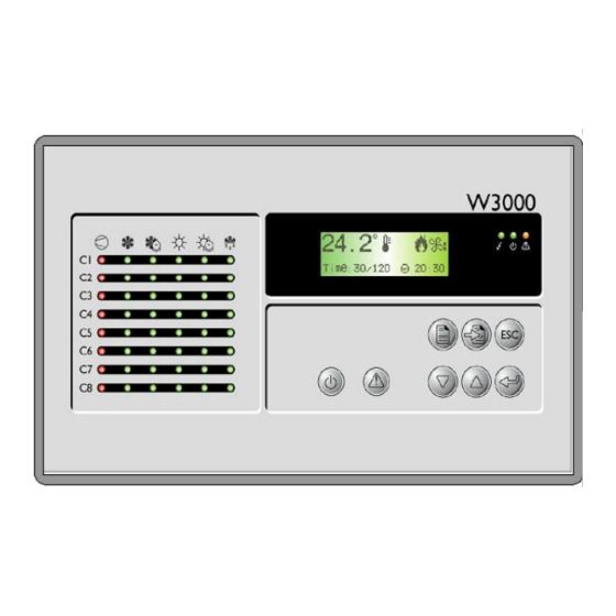
[SETPOINT key]: directly accesses the setpoint menu. [ON/OFF key]: switches the machine on and off. For each compressor, the following LED's are also located on the W3000 user interface: Symbol Colour Description If the LED shines steady the compressor is on, if it flashes the compressor... -
Page 4: Menu Structure
Password Selezione Password Manufacturer Factory Manufacturer Esc / Menù costruttore Menù costruttore costruttore menu selection Password menu Figure 2.1: menu tree for W3000-W3000 compact Setpoint Alarm Menu Tasto Tasto Tasto Power On Menù Setpoint Alarm Display Thermoregulator Termoregolatore Esc / Visual. - Page 5 C0240111-01-06-GB The menus are briefly described below: The “Unit Menu” contains information such as temperature, pressure and circuit states. The “Setpoint menu” is used to set the setpoints for the various available functions. The “I/O menu” shows the status of the digital inputs and values read from the analogue inputs. It also shows the status of the digital outputs and the voltage supplied to the analogue outputs.
-
Page 6: Setting The Connections
C0240111-01-06-GB SETTING THE CONNECTIONS Set the hardware connections before switching on the unit. The inputs/outputs table explaining the functions of the various connectors on the unit is contained in [annex 2] at the end of this manual. 3.1 Available hardware UNIT “B”... - Page 7 C0240111-01-06-GB UNIT “L” UNIT “XL”...
- Page 8 C0240111-01-06-GB EXPANSION “E” W3000...
- Page 9 C0240111-01-06-GB 3.2 Connecting more than one unit Caution: perform the following operations before touching the cards in order to prevent electrostatic discharge: wear the bracelet (connected to the earth circuit) and the heel strap the card should be closed inside an antistatic bag protecting it from electrostatic discharge: remove it from the bag and place it on the light-blue mat with the yellow edge or on the dark-blue mat.
- Page 10 C0240111-01-06-GB EXPANSIONS FOR HERMETIC COMPRESSORS: Additional function Function, chiller type Expansion Expansion address type Recovery enable Chiller with heat recovery Recovery enable Multi-use Heat pump with total heat recovery Freecooling enable Freecooling chiller HP relay enable Chiller with HP relay Low temperature control enable Low temperature chiller Low pressure transducer enable...
- Page 11 C0240111-01-06-GB 3.2.2 “MASTER-SLAVE” CONNECTION Intelligence is distributed instead in the “master- slave” connections. Suppose we have a unit with 4 cooling circuits: t he master card manages circuits 1 and 2 while the slave card manages circuits 3 and 4 .
- Page 12 C0240111-01-06-GB 3.2.3 “MIXED” CONNECTION: The “mixed” connection is used in units with 3/4 cooling circuits where an increase in inputs/outputs is required. The master card manages circuits 1 and 2 while the slave card manages circuits 3 and 4. Additionally, depending on the required functions or the type of machine, cards used simply as expansions can be connected.
- Page 13 C0240111-01-06-GB 3.3 Additional connections In this case set the card address with the following dip-switches: Cards “L”,”XL” Cards ”E” Table of possible combinations: (0 = off, 1= on) Address...
-
Page 14: Configuring The Terminals
The first operation to perform when a network is started up for the first time or a card is replaced, is to perform the procedure for terminal configuration. This cannot be achieved with the basic W3000 keypad. In this case, configure the terminals using the W3000 or W3000 compact keypad and then connect the W3000 basic display. - Page 15 C0240111-01-06-GB 3.4.2 SETTING CARD ADDRESSES The card address is set by the software using the keypad. Proceed as follows: Make sure the keypad address is set to 0 ( see para 3.4.1). Display address Setting..:00 I/O Card address: Disconnect the card from the power supply (turn off the general switch).
- Page 16 To connect several units together and remote control them, thereby forming a plan network (global), a remote keypad controlling all the units is required. The remote keypad cannot be used with a W3000 basic keypad. If a W3000 basic keypad is installed on the machine, replace it with a 3000 compact.
- Page 17 In this case, the various machines of the network are switched by pressing [ESC] and [UP] together. If the plan network does not comprise just W3000 chillers, a 16-key keypad must be used. In this case, press [UNIT] to switch between one card and another. In this case, however, the terminals must be given a special configuration as the 16-key keypad is only recognised on “terminal 3”.
- Page 18 C0240111-01-06-GB CONNECTING THE REMOTE KEYPAD: “T” SHUNT: Let us analyse a vital component for connecting several units in a network: the “T” shunt. This is a shunt with phone connectors (called A,B,C in figure 3.4b). CONFIGURATION: For our purposes, configure terminals J14 and J15 (see Figure 3.4b).
- Page 19 C0240111-01-06-GB SHIELDED TWISTED Figure 3.5 : connecting the remote keypad (for distances less than 200 metres) 2. If a remote keypad monitors more than one unit, the above configuration may only be used for the last card in the network (the nearest to the remote keypad). REMOTE KEYPAD FROM 200 metres UP TO 500 metres N.B.: The remote keypad cannot be installed more than 500 m away.
- Page 20 C0240111-01-06-GB SHIELDED TWISTED Figure 3.6: connecting the remote keypad (for distances between 200 and 500 metres)
-
Page 21: Switching The Unit On And Off
SWITCHING OFF: press the [ON-OFF] key. In the W3000, the message Com. : ON appears on the display In the W3000 base, the message “On” appears on the display with the LED on, or “OFF” with the LED off. using the On/Off parameter: Only in the W3000 and W3000 compact. - Page 22 In the W3000 base the following procedure is used: press [MENU] / select the User menu using the [UP] or [DOWN] keys / press [ENTER] to access the menu / press enter to type in the password / press [UP] or [DOWN] to choose the password and [ENTER] to confirm / use the [UP] or [DOWN] keys to choose the “SPr”...
-
Page 23: User Programming
In the W3000 base the key sequence is: switch off the unit using the [ON/OFF] key / press the [setpoint] key / select MODE with the [UP] or [DOWN] keys / press [Enter] / press [Enter]. At this point the cursor flashes. - Page 24 C0240111-01-06-GB In the W3000 base access the “user menu” / select “DI S” by pressing the [UP or DOWN] key/ press [Enter] to view the current setting / press [Enter] to see the current setting flashing and change it using the [UP or DOWN] key / press [Enter] to confirm the new setting.
-
Page 25: User Menu
C0240111-01-06-GB 5.2) USER MENU The “user menu” is used to display and set important operating, adjustment, setpoint and “recovery” parameters. The physical principles lying at the heart of some special functions are described below. 5.2.1 ) ADJUSTMENT Depending on the type of hardware and the type of compressor used, a choice may be made (for inlet or outlet temperature) between STEP and QUICK MIND adjustment. - Page 26 C0240111-01-06-GB summer ( n° steps=2 ) proportional band Figure 5.1: T is the inlet variable, P is the percentage of delivered power (summer). ▄ = Set + proportional band/2 Winter (n° steps = 2) proportional band Figure 5.2: T is the inlet variable, P is the percentage of delivered power (winter).
- Page 27 C0240111-01-06-GB N° Setpoint Proportional band Theoretical min. Theoretical max. steps (°C) (°C) outlet T outlet T 42.5 41.2 46.3 43.7 46.3 Table 5.2: normally used setpoint and proportional band values according to the number of steps (winter). QUICK MIND ADJUSTMENT METHOD: QUICK MIND adjustment is not available on chillers with recovery or freecooling or multi-purpose.
- Page 28 C0240111-01-06-GB 2 compressors - with maximum permitted number of start-ups per hour 8 Litres/kW 10.5 2 compressors - with maximum permitted number of start-ups per hour 12 Litres/kW 10.5 4 compressors - with maximum permitted number of start-ups per hour 8 Litres/kW 10.5 4 compressors - with maximum permitted number of start-ups per hour 12...
- Page 29 The example shows that outlet temperature varies by about 3.5 °C during regular operation. ADJUSTMENT METHOD FOR CENTRIFUGE COMPRESSORS: The W3000 controller can manage units with centrifuge compressors. The units are combination-adjusted (steps and continuously), with steps for activating the compressors.
- Page 30 C0240111-01-06-GB s e t p o i n t T i n [ ° C ] p r o p o r t i o n a l b a n d s t a r t c o m p r e s s o r 1 s e t p o i n t t [ m i n ] O F F...
- Page 31 C0240111-01-06-GB S e t p o i n t T i n [ ° C ] s e t p o i n t p r o p o r t i o n a l b a n d b a n d a p r o p o r z i o n a l e s t a r t c o m p r e s s o r 2 °...
- Page 32 C0240111-01-06-GB 100% Banda regolazione recupero Recovery adjustment band T.Rec [°C] Recovery Setpoint setpoint recupero Figure 5.10: recovery function of a 4-circuit unit...
- Page 33 “secondary setpoint” function is enabled in the “user menu”). 5.4) CLOCK MENU The clock menu is not enabled in the W3000 base. After enabling time bands from the “enable time bands” parameter in the “user menu”, time bands can be set and specific operating modes and different setpoints can be set according to requirements.
-
Page 34: Manufacturer Programming
C0240111-01-06-GB MANUFACTURER PROGRAMMING The manufacturer menu is not present in the W3000 base. For the other user interfaces, instead, access the manufacturer menu by pressing [Menu] / selecting the manufacturer menu by pressing [UP] / entering the password. The tree diagram of the manufacturer menu is shown in figure 6.1. - Page 35 C0240111-01-06-GB 6.1) FREECOOLING The “freecooling” function is applied to the efficient production of cold water by using external air. The operating principle is illustrated in figure 6.2. FREECOOLING EVAPORATOR COIL “3-way” valve water Figure 6.2: block diagram of the freecooling activation circuit If the external water is cold, the valve closes and the water passes through the coil which cool the water by the water-air heat exchange achieved thanks to the internal fans.
- Page 36 C0240111-01-06-GB dem and Step speed adjustm ent step n° T. in D ynam ic Chiller Dynam ic freecooling band setpoint setpoint Figure 6.3c: fan adjustment in the step mode (example with 8 fans) demand Continuous speed adjustment 100% T. in Dynamic Chiller Dynamic freecooling band...
- Page 37 C0240111-01-06-GB Active Step adjustment steps Step1 on Step2 on Step3 on Step4 on Set Point - Set Point Set Point Set Point Set Point Set Point - Set Point - Set Point - differential differential differential differential Pressure Figure 6.4b: “step” condensation adjustment Condensation Continuous adjustment 100%...
-
Page 38: Alarms
To reset the alarm press the [ALARM] key again and hold it down until the message “No Alarm Active” (for W3000 or W3000 compact) or “No A” (for W3000 base) appears. If the message does not appear it means that one or more alarm conditions are still active. - Page 39 C0240111-01-06-GB Glycol pump overheated (in units with Glycol pump thermal protection freecooling). Master expansion 1 unlinked. Apart from W3000 Expansion 1 no-link base, the word master appears in units with 3 or 4 circuits. Expansion 2 no-link “as above, for expansion 2”...
- Page 40 C0240111-01-06-GB Circuit 4 high pressure “as above, for circuit 4” One of the condensation fans in circuit 1 Circuit 1 fan thermal protection overheated and stopped. Circuit 2 fan thermal protection “as above, for circuit 2” Circuit 3 fan thermal protection “as above, for circuit 3”...
- Page 41 C0240111-01-06-GB Compressor 4 input current “as above, for compressor 4” Compressor 5 input current “as above, for compressor 5” Compressor 6 input current “as above, for compressor 6” “as above, for compressor 7” Compressor 7 input current Compressor 8 input current “as above, for compressor 8”...
- Page 42 C0240111-01-06-GB Exp 2 Probe 6 err “analogue, as above” Exp 2 Probe 7 err “analogue, as above” Exp 2 Probe 8 err “analogue, as above” “analogue, as above” Exp 3 Probe 1 err Exp 3 Probe 2 err “analogue, as above” Exp 3 Probe 3 err “analogue, as above”...
-
Page 43: Annex 1A : Table Of W3000 Masks
C0240111-01-06-GB ANNEX 1a : TABLE OF W3000 MASKS Press [UP] or [DOWN] to move from one mask to another inside the same menu. Press [ENTER] to access the parameter, press [UP] or [DOWN] to change the value of the parameter. - Page 44 C0240111-01-06-GB Enables freecooling control. Freecooling: Enabled: Y 01.15 Access mask to user global parameters submenu. Press "Up" or "Down" to scroll the other masks and "Esc" to return to the submenu. Global. Sets a new password. Enter another ATTENTION: THE PASSWORD ENTERED IN THIS FIELD IS THE ONLY ONE THAT manufacturer password ALLOWS ACCESS TO THE MANUFACTURER MENU!!
- Page 45 C0240111-01-06-GB Sets end pumpdown setpoint and pumpdown timeout. Pumpdown The pumpdown procedure is interrupted… Setpoint 02.5bar - when low pressure falls below the setpoint (if there are transducers on the low pressure 05.25 Max. time section) 05.26 - when the low pressure switch trips (if there are no transducers) - after the timeout (if the procedure is not interrupted by pressure) Sets the cyclical pumpdown time.
- Page 46 C0240111-01-06-GB Sets the period and duration of the power increase impulse. Power incr. impulse: 09.14 Period: 020 s 09.15 Min. dur.: 01.5 s 09.16 Max. dur.: 03.0 s Sets the period and duration of the power decrease impulse. Power decr. impulse: 09.17 Period: 001 s...
- Page 47 C0240111-01-06-GB Sets the enable and disable percentage for each centrifuge compressor. 09.54 Centrifuge Comp. 09.55 off: 09.56 Comp. 7 000% 040% 09.57 Comp. 8 000% 040% Access mask to valves submenu. Press "Up" or "Down" to scroll the other masks and "Esc"...
- Page 48 C0240111-01-06-GB Selects between individual and contemporary condensation. Also sets linear fan Condensation control 17.04 operation. 17.05 Type: Separate Mod.: Linear Selects the type of valve for condensation in water-cooled chillers. Condensation control 17.06 Valve logic: direct Enables pre-condensation (pre-ventilation), sets the duration and defines a value at which Condensation control 17.07 the fans (or condensation valve) run during this phase.
- Page 49 C0240111-01-06-GB Selects the type of control for the freecooling valve, direct or reverse. Also sets the Direct valve 19.04 hysteresis of each fan and the start/stop delay for each fan. Fans 19.05 hysteresis 00.3 °C 19.06 delay Access mask to defrost submenu. Press "Up" or "Down" to scroll the other masks and "Esc"...
- Page 50 C0240111-01-06-GB Sets the parameters for activating the low pressure alarm. Low press. alarm Number of times the alarm has triggered in the previous hour and been reset N° resets 23.03 Start bypass 120 s automatically within the set period, the next time the alarm triggers it must be reset 23.04 manually.
- Page 51 C0240111-01-06-GB Chooses whether, with high/low inlet water temperature, the unit must continue to work (giving a signal) or stop the compressors to prevent them from suffering damage High/Low temp. 23.35 (automatic reset alarm). unit inlet 23.36 Sets the delay before activating the high inlet water temperature (summer mode) / low Type: signal temperature inlet water (winter mode) alarm/signal.
- Page 52 C0240111-01-06-GB Modifies the probe offsets of expansion 2. (Only present if required by the type of machine Master calibr. exp2 27.27 configured) offset Value 27.28 0.0°C 22.4°C The word "master" only appears on units with more than 2 circuits. Modifies the probe offsets of expansion 3. (Only present if required by the type of machine Master calibr.
- Page 53 C0240111-01-06-GB Modifies the probe offsets of expansion 5. (Only present if required by the type of machine Slave calibr. exp5 31.53 configured) offset Value 31.54 0.0°C 00.0°C 0.0°C 00.0°C Access mask to assistance submenu. Press "Up" or "Down" to scroll the other masks and "Esc"...
- Page 54 C0240111-01-06-GB Defines the type of adjustment. (only visible in the step inlet adjustment mode) Input adjustment: 39.05 Type PROPORTIONAL Sets integration time and correction limit (displayed in the step inlet adjustment mode with Integral time: 39.06 proportional + integral adjustment type) 0600 s 39.07 Integral correction...
- Page 55 C0240111-01-06-GB Allows the devices connected to the serial interface card to be enabled and selected ( Serial line "0"=disabled, "1"= supervision, "2"= sequencer). N.B.: the Service software does not need configuration: 39.42 Supervision to be enabled. Allows the on/off status of the unit to be selected from a supervision system. Also En.
- Page 56 C0240111-01-06-GB Setting band A, fourth daily time band. 53.19 Time band 4A Adj. 53.20 Time 13:30 / 19:30 Sp S 07.0°C W 45.0°C 53.21 Sp R 45.0°C 53.22 53.23 53.24 Setting band A, fifth daily time band. 53.25 Time band 5A Off 53.26 Time 19:30 / 19:30 Sp S 08.0°C W 40.0°C...
- Page 57 C0240111-01-06-GB Setting band B, sixth daily time band. 55.31 Time band 6B Off 55.32 Time 19:30 / 19:30 Sp S 09.0°C W 40.0°C 55.33 Sp R 40.0°C 55.34 55.35 55.36 Setting band B, seventh daily time band. 55.37 Time band 7B Off 55.38 Time 19:30 / 19:30 Sp S 09.0°C W 40.0°C...
- Page 58 C0240111-01-06-GB Setting band C, eighth daily time band. 57.43 Time band 8C Off 57.44 Time 19:30 / 19:30 Sp S 09.0°C W 40.0°C 57.45 Sp R 40.0°C 57.46 57.47 57.48 Setting band C, ninth daily time band. 57.49 Time band 9C Off 57.50 Time 19:30 / 19:30 Sp S 09.0°C W 40.0°C...
- Page 59 C0240111-01-06-GB Access mask to In/Out menu. Press "Up" or "Down" to scroll the other masks and "Esc" to return to the submenu. In/Out Displays the state of the digital inputs and specifies their state. C: Contact closed O: Contact open Dig.In.
- Page 60 C0240111-01-06-GB Displays the state of the digital outputs of expansion 2 (if present) and specifies their state. Dig.Out. master exp2 C: Contact closed 12345 67890 12345 O: Contact open AAAAA AAAAA AAAAA Master is only specified on units with 3 or 4 circuits. AAAAA AAAAA AAAA Displays analogue inputs 1 and 2 of expansion 2 (if present).
- Page 61 C0240111-01-06-GB Displays the state of the digital inputs and specifies their state. C: Contact closed Dig.In. slave O: Contact open 12345 67890 12345 The number of inputs displayed depends on the type of unit. (the figures on the second CCCCC CCCCC CCCCC row are for reference purposes) Displays the state of the digital outputs and specifies their state.
- Page 62 C0240111-01-06-GB Displays analogue inputs 3 and 4 of expansion 2 (if present). An. In. slave exp2 N° Value 35.6 °C 40.5 °C Displays analogue inputs 5 and 6 of expansion 2 (if present). An. In. slave exp2 N° Value 22.3 °C 24.2 °C Displays analogue inputs 7 and 8 of expansion 2 (if present).
- Page 63 C0240111-01-06-GB Sets the chiller and heat pump setpoint for inlet adjustment. Chiller setpoint 43.02 07.0 °C 43.03 Heatpump setpoint 43.04 42.5 °C Sets the chiller and heat pump setpoint for outlet adjustment. Chiller setpoint 43.05 11.0 °C 43.06 Heatpump setpoint 45.0 °C Sets the secondary setpoint (only displayed if the secondary setpoint is enabled).
- Page 64 C0240111-01-06-GB Displays the defrosting status of circuits 3 and 4, the delay before defrosting starts and Circ3 Circ4 the time taken to defrost. defr Delay 0904 0000 T.def 0000 0028 Displays the discharge temperature (if probes are present) of compressors 1 and 2. Discharge time Comp.1 105.3°C...
- Page 65 C0240111-01-06-GB Displays the operating status of the centrifugal compressors, the request and effective Work activation, the rpm and the percentage delivered. Req 077 << 082 Act 082% 30850rpm CR 02.88 Displays the operating status of the centrifugal compressors, the request and effective Work activation, the rpm and the percentage delivered.
-
Page 66: Annex 1B : Table Of W3000 Base Masks
C0240111-01-06-GB ANNEX 1b : TABLE OF W3000 base MASKS DISPLAY MASK Unit menu selection Unit menu Setpoint menu selection Setpoint menu Display I/O menu menu selection I/O menu Clock menu selection Clock menu User menu User selection password User menu... - Page 67 C0240111-01-06-GB >CDO1 The submask displays the outlet temperature of condenser 1 > > 22.3 temperature expressed in degrees centigrade >CDO2 (If 2 condensers are present). The submask displays the outlet temperature of condenser 2 > > 22.4 temperature expressed in degrees centigrade The manufacturer menu is not available on this keypad >SALI Evaporator antifreeze alarm setpoint...
- Page 68 C0240111-01-06-GB > > N "N"=disabled, "Y"=enabled 39.35 >PURS (If the "power limiting" parameter is enabled). The submask is used to set the power limitation percentage in the summer mode > > 50 value expressed in percent 39.36 >PURU (If the "power limiting" parameter is enabled). The submask is used to set the power limitation percentage in the winter mode >...
- Page 69 Volts SETP Setpoint menu >MODE The submask is used to set the operating mode (this depends on the machine type set in the manufacturer menu using the W3000-compact keypad) > > CH "CH"= Chiller, "HP"= heat pump 43.01 >ACT...
-
Page 70: Annex 1C : Parameters Table
C0240111-01-06-GB ANNEX 1c : PARAMETERS TABLE N.par. Description of parameter Default U.M. Min. Max. 01.01 Type of unit (0:chiller - 1:heat pump - 2:multi-use) P 99.01 01.02 Type of compressors (0:Centrifuge - 1:hermetic - 2:semi-hermetic - 3:screw) P 99.25 P 99.02 01.03 N°... - Page 71 C0240111-01-06-GB N.par. Description of parameter Default U.M. Min. Max. adjustment) 09.04 Minimum time between start-ups of the same compressor (with step adjustment) 09.05 Maximum number of compressor starts per hour (with Quick Mind adjustment) 09.06 Minimum compressor start-up time (with Quick Mind adjustment) 09.07 Enables 100% screw compressor forcing (0:disabled - 1:enabled) 09.08...
- Page 72 C0240111-01-06-GB N.par. Description of parameter Default U.M. Min. Max. 13.08 Valve configuration in status 7 13.09 Valve configuration in status 8 13.10 Valve configuration in status 9 13.11 Valve configuration in status 10 13.12 Valve configuration in status 11 13.13 Valve configuration in status 12 13.14 Valve 1 release time...
- Page 73 C0240111-01-06-GB N.par. Description of parameter Default U.M. Min. Max. 19.02 Temperature offset for deactivating freecooling -9.0 °C -10.0 P 99.21 19.03 Temperature delta for deactivating freecooling °C P 99.22 19.04 Type of freecooling valve control (0:direct - 1:reverse) 19.05 Hysteresis temperature of individual fans °C 19.06 Start/stop delay for each fan...
- Page 74 C0240111-01-06-GB N.par. Description of parameter Default U.M. Min. Max. 23.34 Maximum pump operation time in alarm mode 23.35 High/low inlet temperature (0:signal - 1:alarm) 23.36 High/low inlet temperature alarm delay 23.37 High inlet water temperature alarm setpoint 30.0 °C P 99.12 40.0 23.38 Low inlet water temperature alarm setpoint...
- Page 75 C0240111-01-06-GB N.par. Description of parameter Default U.M. Min. Max. 31.31 Expansion 3 Slave Probe 1 calibration °C/bar -9.9 31.32 Expansion 3 Slave Probe 2 calibration °C/bar -9.9 31.33 Expansion 3 Slave Probe 3 calibration °C/bar -9.9 31.34 Expansion 3 Slave Probe 4 calibration °C/bar -9.9 31.51...
- Page 76 C0240111-01-06-GB N.par. Description of parameter Default U.M. Min. Max. only) 39.33 Minimum delay between pump start-up and compressor start-up 39.34 Pump shutdown delay 39.35 Enable power limitation (0:No - 1:Yes) 39.36 Power limitation in summer mode (%) 39.37 Power limitation in winter mode (%) 39.38 Power limitation in recovery mode (%) 39.39...
- Page 77 C0240111-01-06-GB Maximum settable limit for configuring the machine type (depends on the type of 99.01 hardware) 99.02 Maximum settable limit for choosing the compressor type 99.03 Maximum limit for the number of circuits (depends on the type of hardware) Maximum limit for the number of compressors (depends on the type of 99.04 hardware) Maximum limit for the number of steps per compressor (depends on the type of...
-
Page 78: Annex 2 : Input/Output Table
C0240111-01-06-GB ANNEX 2 : INPUT/OUTPUT TABLE “L” HARDWARE: a ) for hermetic compressors: WATER-AIR UNIT with “L” axial fans WATER-AIR UNIT with “L” centrifuge fans Digital inputs Digital inputs ID1 Circuit 1 low pressure switch ID1 Circuit 1 low pressure switch ID2 Compressor 1 thermal protection ID2 Compressor 1 thermal protection ID3 Compressor 2 thermal protection... - Page 79 C0240111-01-06-GB “L” WATER-WATER UNIT “L” CONDENSING UNIT Digital inputs Digital inputs ID1 Circuit 1 low pressure switch ID1 Circuit 1 low pressure switch ID2 Compressor 1 thermal protection ID2 Compressor 1 thermal protection ID3 Compressor 2 thermal protection ID3 Compressor 2 thermal protection ID4 Circuit 2 low pressure switch ID4 Circuit 2 low pressure switch ID5 Compressor 3 thermal protection...
- Page 80 C0240111-01-06-GB “L” EVAPORATING UNIT Digital inputs ID1 Circuit 1 low pressure switch ID2 Compressor 1 thermal protection ID3 Compressor 2 thermal protection ID4 Circuit 2 low pressure switch ID5 Compressor 3 thermal protection ID6 Compressor 4 thermal protection ID7 Circuit 1 fan thermal protection ID8 Circuit 2 fan thermal protection ID9 Evaporator flow switch ID10 Remote on/off...
- Page 81 C0240111-01-06-GB b ) for centrifuge compressors: WATER-AIR UNIT with “L” axial fans WATER-AIR UNIT with “L” centrifuge fans Digital inputs Digital inputs ID7 Circuit 1 fan thermal protection ID7 Circuit 1 fan thermal protection ID8 Circuit 2 fan thermal protection ID8 Circuit 2 fan thermal protection ID9 Evaporator flow switch ID9 Evaporator flow switch...
- Page 82 C0240111-01-06-GB “L” WATER-WATER UNIT “L” Digital inputs ID9 Evaporator flow switch ID10 Remote on/off ID11 Pump 1 thermal switch ID12 Pump 2 thermal switch ID13 Circuit 1 high pressure switch ID14 Circuit 2 high pressure switch ID15 ID16 ID17 Compressors enable ID18 Analogue inputs B1 Circuit 1 high pressure transducer...
- Page 83 C0240111-01-06-GB “XL” HARDWARE: WATER-AIR UNIT with “XL” axial fans WATER-AIR UNIT with “XL” centrifuge fans Digital inputs Digital inputs ID1 Circuit 1 low pressure switch ID1 Circuit 1 low pressure switch ID2 Compressor 1 thermal protection ID2 Compressor 1 thermal protection ID3 Compressor 2 thermal protection ID3 Compressor 2 thermal protection ID4 Circuit 2 low pressure switch...
- Page 84 C0240111-01-06-GB “XL” WATER-WATER UNIT “XL” CONDENSING UNIT Digital inputs Digital inputs ID1 Circuit 1 low pressure switch ID1 Circuit 1 low pressure switch ID2 Compressor 1 thermal protection ID2 Compressor 1 thermal protection ID3 Compressor 2 thermal protection ID3 Compressor 2 thermal protection ID4 Circuit 2 low pressure switch ID4 Circuit 2 low pressure switch ID5 Compressor oil 1...
- Page 85 C0240111-01-06-GB “XL” EVAPORATING UNIT Digital inputs ID1 Circuit 1 low pressure switch ID2 Compressor 1 thermal protection ID3 Compressor 2 thermal protection ID4 Circuit 2 low pressure switch ID5 Compressor oil 1 ID6 Compressor oil 2 ID7 Circuit 1 fan thermal protection ID8 Circuit 2 fan thermal protection ID9 Evaporator flow switch ID10 Remote on/off...
-
Page 86: B" Hardware (For Hermetic Compressors)
C0240111-01-06-GB “B” HARDWARE (for hermetic compressors) Water/air chiller with “B” axial fans Water/air chiller with “B” centrifuge fans Digital inputs Digital inputs ID1 Circuit 1 high pressure switch ID1 Circuit 1 high pressure switch ID2 Circuit 2 high pressure switch ID2 Circuit 2 high pressure switch ID3 Remote on/off ID3 Remote on/off... - Page 87 C0240111-01-06-GB “B” WATER-WATER UNIT Digital inputs ID1 Circuit 1 high pressure switch ID2 Circuit 2 high pressure switch ID3 Remote on/off ID4 Remote Summer/Winter ID5 Evaporator flow switch ID6 Circuit 1 low pressure switch ID7 Circuit 2 low pressure switch ID8 Compressor 1 thermal protection ID9 Compressor 2 thermal protection ID10 Pump 1 thermal protection...
-
Page 88: Expansions
C0240111-01-06-GB EXPANSIONS a) for hermetic compressors “E” expansion for chiller with recovery. Expansion "E" – address 1 Digital inputs Digital inputs Recovery flow switch Recovery remote enable Analogue inputs Circuit 1 liquid temperature Circuit 2 liquid temperature Recovery inlet temperature ID10 Recovery outlet temperature ID11... - Page 89 C0240111-01-06-GB “M” expansion for hermetic compressors. Air-cooled polyvalent units and heat pumps with total recovery. Expansion "M" – address 2 Digital inputs Digital inputs Recovery flow switch ID10 ID10 ID11 ID11 ID12 ID12 ID13 ID13 ID14 ID14 ID15 ID16 Analogue inputs ID17 Circuit 1 low pressure transducer ID18...
- Page 90 C0240111-01-06-GB “M” expansion for hermetic compressors. Water-cooled polyvalent units and heat pumps with total recovery. Expansion "M" – address 2 Digital inputs Digital inputs Recovery flow switch Condenser flow switch Condenser pump thermal protection ID10 ID10 ID11 ID11 ID12 ID12 ID13 ID13 ID14...
- Page 91 C0240111-01-06-GB “E” expansion for hermetic compressors. Chiller with freecooling. Expansion "E" – address 3 Digital inputs Digital inputs Glycol pump thermal protection Analogue inputs Circuit 1 low pressure transducer Circuit 2 low pressure transducer Freecooling inlet temperature ID10 ID11 ID12 Digital outputs ID13 Hp relay circuit 1-1...
- Page 92 C0240111-01-06-GB “E” expansion for hermetic compressors. Units with more than 4 compressors. Expansion "E" – address 4 Digital inputs Digital inputs Compressor 5 thermal protection Compressor 6 thermal protection Compressor 7 thermal protection Compressor 8 thermal protection Analogue inputs Step 5 Step 6 Step 7 ID10...
- Page 93 C0240111-01-06-GB b) for semi-hermetic compressors “E” expansions for chillers with heat pumps or two pumps. Expansion "E" – address 5 Digital inputs Digital inputs Remote Summer/Winter Pump 1 thermal protection Pump 2 thermal protection Analogue inputs Evap. 1 outlet water temperature Evap.
- Page 94 C0240111-01-06-GB “E” expansions for chillers with setpoint variation or secondary setpoint. Expansion "E" – address 3 Digital inputs Digital inputs Glycol pump thermal protection Dual setpoint Analogue inputs Setpoint variation (4-20mA) Recovery setpoint variation (4-20mA) Freecooling inlet temperature ID10 ID11 ID12 Digital outputs ID13...
- Page 95 C0240111-01-06-GB “E” expansions for chillers with recovery. Expansion "E" – address 1 Digital inputs Digital inputs Recovery flow switch Recovery remote enable Analogue inputs Circuit 1 liquid temperature Circuit 2 liquid temperature Recovery inlet temperature ID10 Recovery outlet temperature ID11 ID12 Digital outputs ID13...
- Page 96 C0240111-01-06-GB “M” expansion for semi-hermetic compressors. Air-cooled polyvalent units and heat pumps with total recovery. Expansion "M" – address 2 Digital inputs Digital inputs Recovery flow switch ID10 ID10 ID11 ID11 ID12 ID12 ID13 ID13 ID14 ID14 Analogue inputs Analogue inputs Evap.
- Page 97 C0240111-01-06-GB “M” expansion for semi-hermetic compressors. Water-cooled polyvalent units and heat pumps with total recovery. Expansion "M" – address 2 Digital inputs Digital inputs Recovery flow switch Condenser flow switch Condenser pump thermal protection ID10 ID10 ID11 ID11 ID12 ID12 ID13 ID13 ID14...
- Page 98 C0240111-01-06-GB “E” expansions for semi-hermetic compressors. Chiller with freecooling. Expansion "E" – address 3 Digital inputs Digital inputs Glycol pump thermal protection Dual setpoint Analogue inputs Setpoint variation (4-20mA) Recovery setpoint variation (4-20mA) Freecooling inlet temperature ID10 ID11 ID12 Digital outputs ID13 Hp relay circuit 1-1 ID14...
- Page 99 C0240111-01-06-GB “E” expansions for semi-hermetic compressors. Condensing unit or for alternative compressors. Unit with four compressors on two circuits. Expansion "E" – address 4 Digital inputs Digital inputs Compressor 3 thermal protection Compressor 4 thermal protection Compressor oil 3 Compressor oil 4 Analogue inputs Step 1 Step 2...
- Page 100 C0240111-01-06-GB b ) for centrifuge compressors: Expansion “E” Chiller with bypass valves. Expansion "E" – address 1 Digital inputs Digital inputs Analogue inputs ID10 ID11 ID12 Digital outputs ID13 Injection 1 ID14 Injection 2 ID15 Injection 3 ID16 Injection 4 ID17 ID18 Analogue outputs...
- Page 101 C0240111-01-06-GB SYMBOLS The following symbols are used in the W3000 and W3000 compact masks. Symbol Description Unit/circuit off Ch nr Chiller circuit not demanded by thermoregulator Chiller circuit demanded by thermoregulator Ch+R Chiller circuit plus recovery demanded by thermoregulator Hp nr...
Need help?
Do you have a question about the W3000 and is the answer not in the manual?
Questions and answers