Table of Contents
Advertisement
Quick Links
Download this manual
See also:
User Manual
Advertisement
Table of Contents

Subscribe to Our Youtube Channel
Related Manuals for Uniclass HX120T


Summary of Contents for Uniclass HX120T
- Page 1 User's Manual HX120T/R/W HDMI AV Matrix Extender & Video Wall Version : 0.77...
-
Page 2: Table Of Contents
Introduction ........................ 3 Features ........................3 Specification ....................... 4 Package contents ...................... 4 Product overview ...................... 5 Connection ........................6 Connecting the local unit (Transmitter) ............6 Connecting the remote unit (Receiver) ............7 Connecting the local (Transmitter) and remote (Receiver) unit ....7 Point to point ....................... -
Page 3: Introduction
Support Digital Video resolution of 1920x1200 @60Hz Bi-directional IR pass-through for added convenience Complaint to HDMI 1.3 CEC specification Support 7.1 audio channel Support A/V Matrix up to 256x256 (HX120T/HX120R Combo) Support RS232/UART Extension function Support 8x8 Video Wall (HX120T/HX120W Combo) -
Page 4: Specification
Specification Model No. HX120T HX120R HX120W Product Description HDMI AV Matrix Extender & HDMI AV Matrix Extender - HDMI AV Matrix Extender & Video Wall - Transmitter Receiver Video Wall - Receiver Console USB Hub Ports 2 x USB 2.0 Type A Female 2 x USB 2.0 Type A Female... -
Page 5: Product Overview
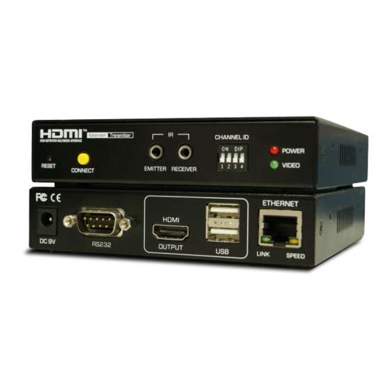
Product overview Transmitter Front panel Rear panel Receiver Front panel Rear panel Video Wall Front panel Rear panel No. Item Description Reset Press to re-start the unit. Connect Press to re-connect the Transmitter/Receiver if the DIP switch has been reset. ■... -
Page 6: Connection
Connection Before connecting the HDMI AV Matrix Extender with an Ethernet Hub/Switch, please read the notices mentioned below 1. When grouping the network of HDMI AV matrix Extender/Video wall, a Gigabit Ethernet Hub/Switch is necessary due to the requirement of bandwidth. The required bandwidth for each channel may up to 200mb/sec. -
Page 7: Connecting The Remote Unit (Receiver)
Connecting the remote unit (Receiver) Connect the power adapter to a wall outlet. Connect a display to HDMI output of Receiver using a HDMI cable. Connect a USB device to USB type A connector of Receiver using a USB cable. Connecting the local (Transmitter) and remote (Receiver) unit Point to point USB devices... -
Page 8: Point To Multipoint
Point to multipoint USB devices Receiver Receiver Receiver Receiver Transmitter Gigabit Ethernet Switch A/V source or PC ■ Except the point to point connection, the Transmitter can be extended to several Receivers using a gigabit Ethernet switch. Video Wall With the combination of Transmitter and Video Wall, the HDMI signal can be sent to one or multi HDMI display up to 8x8 using a single Cat5 cable. -
Page 9: Bi-Directional Ir Connection
Note: For the better performance of video and matrix display, using the same brand, size and model monitors are strongly recommended. Note: The lag of displays may occur sometimes. The image quality is depending on the speed of network or the equipments, such as the grade of hub. -
Page 10: Remote Control
Remote control HDMI CEC remote CEC (Consumer Electronics Control) is one of features of HDMI that allows HDMI devices to control each other using only one remote control. To achieve the HDMI CEC remote by the HDMI AV Matrix Extender, please refer to the notes below. -
Page 11: Rs-232 Control
RS-232 control The HDMI AV Matrix Extender not only extends HDMI signal but also RS-232, and allows user to control from local PC remotely. Receiver (remote unit) RS232 device Transmitter (loacl unit) Connect RS232 connector to a PC, and plug the other end of connector into the female connector of Transmitter. -
Page 12: Operation
Operation To operate the HDMI AV Matrix Extender, two ways are provided. 1. Operate by adjusting the DIP manually. 2. Setup from web user interface. Control manually With the convenient push button and DIP Switch on the front panel, user can quickly and easily to operate the HDMI AV Matrix Extender directly. -
Page 13: Identify The Unit
MAC address which labeled on the bottom of the devices. For example, if the MAC address of Transmitter is 00:11:AA:CB:00:01, the device will be named to HX120T-CB0001. T is for Transmitter, R is for Receiver and W is for Video Wall. IP address assignment 4. - Page 14 6. Click Internet Protocol Version 4 (TCP/IPv4), and then click Properties. 7. Click Use the following IP address to specify an IP address that is on the same subnet as Transmitter/Extender Receiver/VideoWall Receiver.
-
Page 15: Web Ui
Web UI ■ To configure each unit of HDMI AV Matrix AV Extender , open a browser and type the IP address which you got from Bonjour Browser. The corresponding web page will appear on the screen as following. ■ Click Apply once you have changed the settings. Transmitter Item Sub-item... - Page 16 Item Sub-item Option Description Function Serial over IP Baudrate setting Setup the baudrate settings. Baudrate settings ■ This option allows to set the baudrate of Transmitter, Extender Receiver/VideoWall Receiver manually. Make sure the settings must match with the RS-232 device you have connected. By default, the system settings are as following: Baudrate: 115200 Data bits: 8...
- Page 17 Item Sub-item Option Description Channel Select a desired channel from the Transmitters. Pairing the Transmitter and Receiver ■ When grouping the network of HDMI AV Matrix Extender/Video Wall using multipoint to multipoint, the channel selections may be complicated. This option allows user to select the channel more intuitively.
- Page 18 Item Sub-item Option Description Function Video over IP Enable/disable the copy function from EDID compliant monitors automatically. Serial over IP Baudrate setting Setup the baudrate settings. Baudrate settings ■ This option allows to set the baudrate of Transmitter, Extender Receiver/VideoWall Receiver manually. Make sure the settings must match with the RS-232 device you have connected.
- Page 19 Item Sub-item Option Description Video Wall Bezel and Gap Adjust the compensation for bezel between panels. Compensation Wall Size and Position Setup the display quantities, and specify the positions for each display. Layout...
- Page 20 Bezel and Gap Compensation Outline Width Visible Width ■ Enter the values to the outline width, visible height, outline height and visible width respectively according to the bezels of monitors. ■ Click the Apply once the values have been set. ■...
- Page 21 1x2 Video Wall (example) To extend the display on the Video Wall, setup the Wall Size and Position Layout by following the table below: Monitor 1 Numbers of Row Numbers of Column Row Position Column Position Monitor 2 Numbers of Row Numbers of Column Row Position Column Position...
- Page 22 Item Sub-item Option Description Channel Select a desired channel from the Transmitters. Item Sub-item Option Description Network IP Setup DHCP/Static Select DHCP to obtain IP address automatically or select Static to assign an IP manually. Device Mode Matrix/Extender Select the operation mode depending on the connection requirements.
- Page 23 Item Sub-item Option Description Function Video over IP Enable/disable the copy function from EDID compliant monitors automatically. Serial over IP Baudrate setting Setup the baudrate settings. EDID configuration ■ To copy the EDID information, tick the option of Copy EDID from this Video Output. The EDID information will be copied each time power on the Receiver.
-
Page 24: Osd Control
HX120W-D0001C Select Channel Select Channel Scan node About HX120T-C80006 HX120T-C80007 [HX120T-C80008] HX120T-C80009 2. The device ID will appear on the screen. To specify the desired device, press Left or Right button. Once the device has been confirmed, press OK to bring up more options. -
Page 25: Additional Options
Additional options ■ Select Scan node to refresh if more devices have been connected. ■ Select About to show the firmware version. HDMI CEC Except the remote control (optional), remote the device through HDMI CEC is supported as well. The operation is similar with the remote control described above. -
Page 26: Technical Support
Technical support Please contact with your local distributor for more information or technical support. FCC / CE Statements FCC Statement : This equipment has been tested and found to comply with the regulations for a Class B digital device, pursuant to Part 15 of the FCC Rules. These limits are designed to provide reasonable protection against harmful interference when the equipment is operated in a commercial environment.
Need help?
Do you have a question about the HX120T and is the answer not in the manual?
Questions and answers