Philips DVP3140 Service Manual
Hide thumbs
Also See for DVP3140:
- Service manual (55 pages) ,
- User manual (45 pages) ,
- Specifications (2 pages)
Advertisement
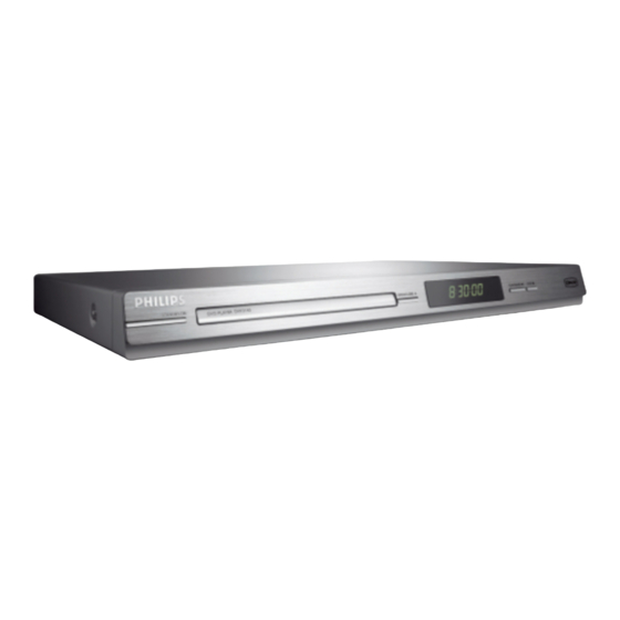
DVD Player
Service
Service Manual
TABLE OF CONTENTS
. Technical Specifications........................................................1-2
. Safety Instruction, Warning & Notes.......................................
. Mechanical and Dismantling Instructions....................................2-1
. Region Code, Software Version& Upgrades.............................
. Trouble Shooting Chart...................................................... .. 4-1
. Wiring Diagram..................................................................,5-1
. Electrical Diagrams and Print-layouts.......................................6-1
. Set Mechanical Exploded view..................................................
. Revision List.........................................................................8-1
©Copyright 2007 Philips Consumer Electronics B.V. Eindhoven, The Netherlands
All rights reserved. No part of this publication may be reproduced, stored in aretrieval system or
transmitted, in any form or by any means, electronic, mechanical, photocopying, or otherwise
without the prior permission of Philips.
Published by KC-0747 Service Audio
Version 1.3
Printed in The Netherlands
Subject to modification
DVP3140,DVP3142(K),DVP3144
DVP3140/37
DVP3142/12/51/55
DVP3142K/55/77/78
DVP3142KM/78
DVP3144/12/75
DVP3144K/55
Page
1-3
.
.
3-1
.. .
7-1
.
LASER PRODUCT
GB
PHILIPS
CLASS 1
3139 785 32452
Advertisement

Related Manuals for Philips DVP3140


Summary of Contents for Philips DVP3140
-
Page 1: Table Of Contents
. Set Mechanical Exploded view....…………………..….….. . Revision List…..………………………………………..…..…..8-1 CLASS 1 ©Copyright 2007 Philips Consumer Electronics B.V. Eindhoven, The Netherlands LASER PRODUCT All rights reserved. No part of this publication may be reproduced, stored in aretrieval system or transmitted, in any form or by any means, electronic, mechanical, photocopying, or otherwise without the prior permission of Philips. -
Page 2: Technical Specifications
Technical Specifications Audio performance TV standard (PAL/50Hz) (NTSC/60Hz) DA converter 24bits, 192KHz Number of lines fs 96kHz 4Hz----44kHz Playback Multi standard (PAL/NTSC) fs 48kHz 4Hz----22kHz SVCD fs 48kHz 4Hz----22kHz Video performance fs 44.1kHz 4Hz----20kHz CD/ VCD fs 44.1kHz 4Hz----20kHz Video DAC 12 bit, 108MHz Signal-Noise (1kHz) >90dB... -
Page 3: Safety Instruction, Warning & Notes
Safety instruction, Warning & Notes Safety instruction 2.Laser safety 1. General safety This unit employs a laser. Only qualified service personnel Safety regulations require that during a repair: may remove the cover, or attempt to service this device . Connect the unit to the mains via an isolation transformer. (due to possible eye injury). - Page 4 Warning 2. Laser 1.General . All ICs and many other semiconductors are susceptible to . The use of optical instruments with this product, will electrostatic discharges (ESD). Careless handing during increase eye hazard. repair can reduce life drastically. Make sure that, during .
- Page 5 - lead free BGA-ICs will be delivered in so-called respected by the workshop during a repair: ‘dry-packaging’ (sealed pack including a silica gel Use only lead-free solder alloy Philips SAC305 with pack) to protect the IC against moisture. After order code 0622 149 00106. If lead-free solder-paste is...
-
Page 6: Mechanical And Dismantling Instructions
Mechanical and Dismantling Instructions Dismantling Instruction The following guidelines show how to dismantle the player. Step1: Remove 5 screws around the Top Cover, then remove the Top Cover (Figure 1). Figure 1 Step2: If it is necessary to dismantle Loader or Front Panel, It should be remove the Front door assembly first. (Figure 2) Note: Make sure to operate gently otherwise the guider would be damaged. - Page 7 Mechanical and Dismantling Instructions Dismantling Instruction Step3: If the tray can’t open in normal way, you can make it through the instruction as below (Figure 3). Note: Make sure to operate gently otherwise the guider would be damaged. Push the guider until the tray out. Make sure to operate gently to Figure 3 avoid damage happening.
- Page 8 Mechanical and Dismantling Instructions Dismantling Instruction Step5: Dismantling Front Panel, disconnect the 1 connector, then release the snaps on the both sides of Front Panel and bottom cabinet , then gently pull the Panel out from the set. (Figure 5 & 6 & 7) CON 5 CON 4 Figure 5...
- Page 9 Mechanical and Dismantling Instructions Dismantling Instruction Step6: Dismantling Main Board, first disconnect the connector, and then remove 4 screws. (Figure 8) CON 6 Figure 8 Step7: Remove the 2 screws on Power Board to dismantle the Power Board. (Figure 9) Figure 9...
-
Page 10: Software Upgrade
Software upgrade Preparation to upgrade software B. Read out the software versions to confirm upgrading Start the CD Burning software and create a new CD Power up the set and open the tray door. project (Data Disc) with the following setting: Press <9><6><6>... -
Page 11: Trouble Shooting Chart
Trouble shooting chart Spindle motor does not move Remark: Trouble shooting chart for DVP3140/XX Motor no move Check the FFC connection Correct connection between 24P and the loader. Check whether “RFA5V” Check the RFA5V power (+5V) voltage is normal. supply Check whether laser voltage Check/Replace Q2 Q3.
Need help?
Do you have a question about the DVP3140 and is the answer not in the manual?
Questions and answers