Table of Contents
Advertisement
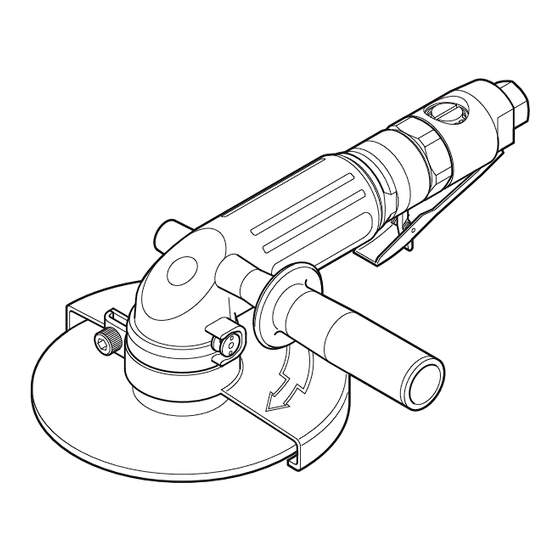
PNEUMATIC ANGLE GRINDER
Please read this manual carefully before you attempt to use
your tool so that you may use it properly and safely.
MYTON
PROFESSIONAL TOOL
Model
Maximum Operating Pressure
Air Consumption
(No Load)
Maximum Power
Rated Speed (No Load)
Diameter
Depressed Center
Grinding Wheel
Hole
Mass (Weight)
Sound Pressure Level
Sound Power Level
Body
Vibration Level
[Uncertainty K]
Handle
Thread Size of Air Inlet
Due to continuous product development/improvement the specifications and
configurations in this document are subject to change without prior notice.
Keep the manual handy – so you can use it whenever necessary.
Model MLG-25, MLG-40, MLG-50, MLG-70
MLG-25
MLG-50
Specifications
MLG-25
MPa
3
m
/min
0.42
W
210
-1
r/min(min
)
19,000
mm(inch) 58 (2-9/32)
mm(inch)
9.6 (3/8)
kg
0.6
dB(A)
90
dB(A)
95
2.5
2
2
m/s
[m/s
]
(1.8 [0.83])
2
2
m/s
[m/s
]
Rc1/4
MLG-40
MLG-70
MLG-40
MLG-50
MLG-70
0.6
0.45
0.7
710
1,100
13,000
11,000
100 (4)
125 (5)
16 (5/8)
22 (7/8)
1.4
2.5
88
89
99
100
6.3 [1.10]
3.6 [0.85]
3.8 [0.87]
4.1 [0.90]
6.2 [1.10]
Rc3/8
Rc3/8
Manufactured by :
NITTO KOHKI Co., Ltd.
2-9-4, Nakaikegami, Ohta-ku,
Tokyo, 146-8555, Japan
TEL
: (81)-3-3755-1111
FAX
: (81)-3-3753-8791
E-mail : overseas@nitto-kohki.co.jp
URL : www.nitto-kohki.co.jp
Original Instructions
0.7
1,100
7,600
180 (7)
22 (7/8)
2.5
89
100
Rc3/8
Advertisement
Table of Contents

Related Manuals for Nitto MYTON MLG-25


Summary of Contents for Nitto MYTON MLG-25
- Page 1 Rc3/8 Rc3/8 Due to continuous product development/improvement the specifications and configurations in this document are subject to change without prior notice. Manufactured by : NITTO KOHKI Co., Ltd. 2-9-4, Nakaikegami, Ohta-ku, Tokyo, 146-8555, Japan : (81)-3-3755-1111 : (81)-3-3753-8791 E-mail : overseas@nitto-kohki.co.jp URL : www.nitto-kohki.co.jp...
-
Page 2: Table Of Contents
Thank you very much for your purchase of this CONTENTS page IMPORTANT SAFETY INSTRUCTIONS …………………… 2 Nitto Kohki product. GENERAL: TOOLS …………………………………………… 2 Before using your tool, please read this manual GENERAL: PNEUMATIC TOOLS ………………………… 3 carefully so that you may use it properly to get INSTRUCTIONS FOR THIS TOOL …………………………... -
Page 3: Important Safety Instructions
IMPORTANT SAFETY BEFORE OPERATION INSTRUCTIONS Inspect tool before use. Before using, check that screws are securely When using the tool, please observe the safety tightened, that any protective cover or guard is precautions below to prevent possible accident or securely in place, other parts are free from damage injury. -
Page 4: General: Pneumatic Tools
Handle tool carefully. occurrence. Abusive use of tool could invite failure or accident. To obtain a Nitto genuine part, consult this Manual Do not throw, drop or shock the tool. or contact the sales agent from which you have Handle connecting hose carefully. -
Page 5: Instructions For This Tool
Wheels to make sure there is no problem on the any wheels wet or without labels. grinder. Use Nitto Kohki’s Wheel Flanges only. However, Grind slowly until the Grinding Wheels get do not use any of them which have cracks, chips warmer in case Wheels seem cold at the start. -
Page 6: Usage
1set Hex. Socket Screw Key 6 MLG-25 Hex. Socket Screw Key 4 Package Contents Check Pin Face Wrench MYTON MLG-25 1set Bushing R3/8×NPT3/8 Grinding Wheel GS #80 Instruction Manual Hex. Socket Screw Key 5 Declaration of Conformity Single Ended Spanner 19 Caution for Use Bushing R1/4×NPT1/4... -
Page 7: Air Supply
4. AIR SUPPLY 5. PREPARATION (MLG-50, MLG-70) Mounting the Handle Ass’y CAUTION Screw the Handle Ass’y into the Housing Sub Ass’ y. It can be mounted on either right or left side of the Draw off drainage before starting operation. If Housing Sub Ass’y. -
Page 8: Mounting And Removing Grinding Wheel
MLG-50 Spindle Spanner Grinding Wheel Fig. 6 Outer Flange MLG-70 Hex. Socket Screw Key 5 Fig. 8 7-2. MLG-40, MLG-70 Mounting 1. Insert the Outer Flange into the center hole of the Fig. 7 Grinding Wheel. 2. While depressing the Spindle Lock Button lightly, place the Driving Flange on the Spindle and MLG-25 MLG-40... -
Page 9: How To Operate The Tool
7-3. MLG-50 8. HOW TO OPERATE THE TOOL Mounting 8-1. Start and Stop 1. Hold the Spindle with pushing the Lock Button. To start, release the lock lever and grasp the throttle 2. Insert the Driving Flange into the Spindle to fit lever. -
Page 10: Storage
2. Remove E haust Cover E haust Port E haust Plate Spacer Grease Port (M4 Screw) Packing Cover 1. Loosen Screw 4 12 Toothed Washer CW-4 Fig. 14 Fig. 13 9. STORAGE CAUTION: When tool is not used, store it out of reach of children. -
Page 11: Ordering Service Parts
For further operational and handling information or for replacement of parts and components, contact the company from whom you purchased the tool or an authorized dealer. In ordering parts and components give each part number, part name and quantity required. Use only NITTO genuine parts. -
Page 12: Exploded Diagram : Mlg-25
This diagram is for your reference only. Do not attempt to service or repair the Tool. Do not take the Tool apart. Contact an authorized Nitto dealer for all service and repair of the Tool. Improper service and repair can cause accidents and service injuries. -
Page 13: Exploded Diagram : Mlg-40
This diagram is for your reference only. Do not attempt to service or repair the Tool. Do not take the Tool apart. Contact an authorized Nitto dealer for all service and repair of the Tool. Improper service and repair can cause accidents and service injuries. -
Page 14: Exploded Diagram : Mlg-50
This diagram is for your reference only. Do not attempt to service or repair the Tool. Do not take the Tool apart. Contact an authorized Nitto dealer for all service and repair of the Tool. Improper service and repair can cause accidents and service injuries. -
Page 15: Exploded Diagram : Mlg-70
This diagram is for your reference only. Do not attempt to service or repair the Tool. Do not take the Tool apart. Contact an authorized Nitto dealer for all service and repair of the Tool. Improper service and repair can cause accidents and service injuries. - Page 16 Printed in KOREA TQ12673-6...
Need help?
Do you have a question about the MYTON MLG-25 and is the answer not in the manual?
Questions and answers