Table of Contents
Advertisement
Quick Links
Service Manual
Supplement
The construction of model DC-DA180 is similar to model DC-DA170. The differences between these models require the bellow
specified items. Please also refer to the original service manual DC-DA170 (SM5810187) for other items.
Contents
Exploded View (Cabinet & Chassis ) .......................................... 1
Parts List ..................................................................................... 2
Memo .......................................................................................... 5
Schematic Diagram (FRONT) ..................................................... 6
Wiring Diagram (FRONT & CD) .................................................. 8
Schematic Diagram (AMP) ......................................................... 10
Wiring Diagram (AMP) ................................................................ 12
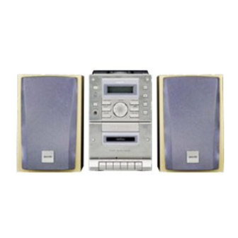
This service manual consists of "DC-DA180U"(Main unit: 129 631 03) and "SX-DA180/SP" (Speaker model: 165 055 00).
May. / '02
BB
Printed in Japan.
Micro Component System
OFF
ON
TUNER/ BAND
FUNCTION
PRESET
PHONES
MEMORY
REC
PLAY
SANYO Electric Co., Ltd.
Osaka, Japan
FILE NO.
DC-DA180
VOLUME
SURROUND
TU UP
/
BASS
XPANDER
TU DOWN
/
SOUND PRESET
DOWN
UP
PUSH TO CLOSE
REW
F FWD
STOP/ EJECT
PAUSE
/
PRODUCT CODE No.
129 632 03
REFERENCE No. SS5810307
(AU)
Advertisement
Table of Contents

Related Manuals for Sanyo DC-DA180


Summary of Contents for Sanyo DC-DA180
- Page 1 F FWD STOP/ EJECT PAUSE The construction of model DC-DA180 is similar to model DC-DA170. The differences between these models require the bellow specified items. Please also refer to the original service manual DC-DA170 (SM5810187) for other items. PRODUCT CODE No.
- Page 2 EXPLODED VIEW (CABINET & CHASSIS) - 1 -...
-
Page 3: Parts List
PARTS LIST PRODUCT SAFETY NOTICE EACH PRECAUTION IN THIS MANUAL SHOULD BE FOLLOWED DURING SERVICING. COMPONENTS IDENTIFIED WITH THE IEC SYMBOL IN THE PARTS LIST AND THE SCHEMATIC DIAGRAM DESIGNATED COMPONENTS IN WHICH SAFETY CAN BE OF ! ! ! SPECIAL SIGNIFICANCE. - Page 4 PARTS LIST REF.NO. PART NO. DESCRIPTION FRONT P.W.BOARD SSSY SE601 407 217 1101 PHOTO DIODE SPS-442-1G REF.NO. PART NO. DESCRIPTION X6001 645 032 6424 OSC,CRYSTAL 4.5MHZ 614 323 4111 ASSY,PWB FRONT (Only initial) 645 051 7587 OSC,CRYSTAL 4.5MHZ BR601 614 314 1204 HOLDER,LCD,HOLDER_LCD 614 324 1317 SHIELD,CUSHION BR602 614 315 7038 COVER,LED,COVER_LED...
- Page 5 PARTS LIST REF.NO. PART NO. DESCRIPTION Q4106 405 109 9204 TR KRC102M-A 405 000 3103 TR DTC114ES Q4107 405 146 2206 TR KTC3875-GR 405 146 2107 TR KTC3875-Y 405 011 1006 TR 2SC1623-L6 405 014 4509 TR 2SC2412K-R Q4108 405 146 2206 TR KTC3875-GR 405 146 2107 TR KTC3875-Y 405 011 1006 TR 2SC1623-L6 405 014 4509 TR 2SC2412K-R...
- Page 6 MEMO - 5 -...
Need help?
Do you have a question about the DC-DA180 and is the answer not in the manual?
Questions and answers