Table of Contents
Advertisement
Quick Links
Service Manual
CONTENTS
Laser Beam Safety Precaution ........................................ 1
Tuner Adjustment ............................................................. 2
Tape eck Adjustment ....................................................... 3
Exploded View (Accessories & Packing) ......................... 4
Exploded View (Cabinet & Chassis) ................................ 5
Parts List .......................................................................... 6
Wiring Connection ............................................................ 9
Schematic Diagram .......................................................... 10
Wiring Diagram ................................................................ 18
All manuals and user guides at all-guides.com
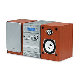
Micro Component System
FILE NO.
DC-DA1400M
(AU)
PRODUCT CODE No.
129 716 01
SM
5810776
REFERENCE No.
Advertisement
Table of Contents

Related Manuals for Sanyo DC-DA1400M


Summary of Contents for Sanyo DC-DA1400M
-
Page 1: Table Of Contents
All manuals and user guides at all-guides.com FILE NO. DC-DA1400M Service Manual (AU) Micro Component System PRODUCT CODE No. CONTENTS 129 716 01 Laser Beam Safety Precaution ........1 Tuner Adjustment ............. 2 Tape eck Adjustment ............3 Exploded View (Accessories & Packing) ......4 Exploded View (Cabinet &... -
Page 2: Laser Beam Safety Precaution
All manuals and user guides at all-guides.com LASER BEAM SAFETY PRECAUTION • Pickup that emits a laser beam is used on this CD section. CAUTION : USE OF CONTROLS OR ADJUSTMENTS OR PERFORMANCE OF PROCEDURES OTHER THAN THOSE SPECIFIED HEREIN MAY RESULT IN HAZARDOUS RADIATION EXPOSURE. -
Page 3: Tuner Adjustment
All manuals and user guides at all-guides.com TUNER ADJUSTMENTS Use a plastic screw driver for adjustments. Adjust the intermediate frequency of AM to the frequency of ceramic filter. Set of unit Supply voltage AC 230V speaker impedance 4 ohms standard output 50 mW Function select: TUNER... -
Page 4: Tape Eck Adjustment
All manuals and user guides at all-guides.com TAPE DECK ADJUSTMENTS 1. HEAD REPLACEMENT After replacement, demagnetize. The heads by using a degausser. Be sure to clean the heads before attempting to make any adjustments. All wiring should be returned to the original position after work is completed. 2. -
Page 5: Exploded View(Accessories & Packing)
All manuals and user guides at all-guides.com EXPLODED VIEW(ACCESSORIES & PACKING) - 4 -... -
Page 6: Exploded View(Cabinet & Chassis)
All manuals and user guides at all-guides.com EXPLODED VIEW(CABINET & CHASSIS) - 5 -... -
Page 7: Parts List
645 080 4953 SPEAKER 1.5",SMALL 645 069 7357 POLY BAG,SPEAKER 645 080 4960 SPEAKER 3.5",LARGE 645 027 2080 POLY BAG,AM LOOP ANT 645 076 1515 SANYO LOGO 645 061 6297 ANTENNA LOOP 645 080 5721 ASSY SPEAKER BOX L,LEFT 645 080 5714 REMOTE CONTROL,... - Page 8 All manuals and user guides at all-guides.com PARTS LIST CONTROL P.W.BOARD ASSY REF.NO. PART NO. DESCRIPTION L0101 645 023 6297 VHF COIL REF.NO. PART NO. DESCRIPTION L0102 645 023 6280 FM COIL 614 334 4285 ASSY,PWB CONTROL(Only initial) L0104 645 027 0352 CHOKE COIL 100UH C0744 645 055 6784 GOLD CAP DX-5R5H104 Q0107...
- Page 9 All manuals and user guides at all-guides.com PARTS LIST REF.NO. PART NO. DESCRIPTION Q0408 645 023 6129 TR 9014C Q0409 645 023 6129 TR 9014C Q0410 645 023 6129 TR 9014C Q0411 645 055 6883 TR KSA928A Q0412 645 027 0420 TR 8050C Q0414 645 023 6129 TR 9014C Q0601...
-
Page 10: Wiring Connection
All manuals and user guides at all-guides.com WIRING CONNECTION AM ANT FM ANT AC CORD POWER TRANSFORMER This is a basic wiring connection. - 9 -... -
Page 11: Schematic Diagram
All manuals and user guides at all-guides.com SCHEMATIC DIAGRAM (AUDIO) This is a basic schematic diagram. - 10 - - 11 -... - Page 12 All manuals and user guides at all-guides.com SCHEMATIC DIAGRAM (CD) This is a basic schematic diagram. - 12 - - 13 -...
- Page 13 All manuals and user guides at all-guides.com SCHEMATIC DIAGRAM (CONTROL) This is a basic schematic diagram. - 14 - - 15 -...
- Page 14 All manuals and user guides at all-guides.com SCHEMATIC DIAGRAM (TUNER) SCHEMATIC DIAGRAM (STD RECORDING) - 16 - - 17 -...
-
Page 15: Wiring Diagram
All manuals and user guides at all-guides.com WIRING DIAGRAM (CD) - 18 - - 19 -... - Page 16 All manuals and user guides at all-guides.com WIRING DIAGRAM (CONTROL) - 20 - - 21 -...
- Page 17 All manuals and user guides at all-guides.com WIRING DIAGRAM (TUNER) - 22 - - 23 -...
- Page 18 All manuals and user guides at all-guides.com WIRING DIAGRAM (STDS RECORDING) WIRING DIAGRAM (AUIDIO) SANYO Electric Co., Ltd. Osaka, Japan Sep./ '05 / Printed in Japan - 24 - - 25 -...
Need help?
Do you have a question about the DC-DA1400M and is the answer not in the manual?
Questions and answers