Table of Contents
Advertisement
Advertisement
Table of Contents

Related Manuals for Unimig RAZOR 320 AC/DC


Summary of Contents for Unimig RAZOR 320 AC/DC
- Page 1 RAZOR 320 AC/DC KUMJRRW320ACDC | Operating Manual...
-
Page 3: Table Of Contents
CONTENTS SAFETY TECHNICAL DATA WHAT’S IN THE BOX MACHINE LAYOUT CONTROL PANEL LAYOUT SETUP FOR TIG TIG CONTROL PANEL OPERATION TIG WELDING GUIDE SETUP FOR STICK (MMA) WELDING MMA CONTROL PANEL OPERATION MMA (STICK) ADDITIONAL NOTES MMA (STICK) WELDING GUIDE TORCH BREAKDOWN &... -
Page 4: Safety
SAFETY Welding and cutting equipment can be dangerous to both the operator and people in or near the surrounding working area if the equipment is not correctly operated. Equipment must only be used under the strict and comprehensive observance of all relevant safety regulations. Read and understand this instruction manual carefully before the installation and operation of this equipment. - Page 5 SAFETY Fire hazard. Welding/cutting on closed containers, such as tanks, drums, or pipes, can cause them to explode. Flying sparks from the welding/cutting arc, hot workpiece, and hot equipment can cause fires and burns. Accidental contact of the electrode to metal objects can cause sparks, explosion, overheating, or fire. Check and be sure the area is safe before doing any welding/cutting.
- Page 6 SAFETY CAUTION 1. Working Environment. The environment in which this welding/cutting equipment is installed must be free of grinding dust, corrosive chemicals, flammable gas or materials etc., and at no more than a maximum of 80% humidity. ii. When using the machine outdoors, protect the machine from direct sunlight, rainwater and snow, etc.; the temperature of the working environment should be maintained within -10°C to +40°C.
- Page 7 SAFETY ATTENTION! - CHECK FOR GAS LEAKAGE At initial set up and at regular intervals we recommend to check for gas leakage Recommended procedure is as follows: 1. Connect the regulator and gas hose assembly and tighten all connectors and clamps. 2.
-
Page 8: Technical Data
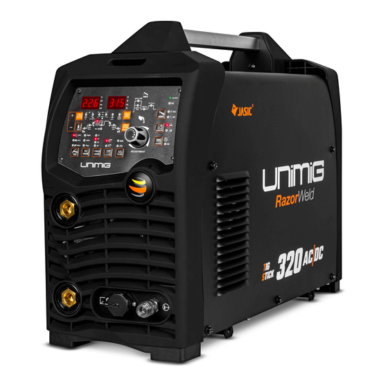
TECHNICAL DATA RAZOR™ 320 AC/DC TIG/STICK Welder Key Features: • AC/DC High-Frequency TIG • Pulse TIG Function • AC TIG Waveforms - Square, Trapezoidal, Sine • Mixed Arc AC/DC • Foot Control Ready • 2T/4T Torch Modes • Remote Control Module TECHNICAL DATA DC TIG SETTINGS SKU KUMJRRW320ACDC... -
Page 9: What's In The Box
(Mix) SPOT TORCH ADJUSTMENT WAVE MODE PULSE LIFT ARC RAZOR 320 AC/DC TIG/STICK Welder 4m T3 TIG Torch 4m Electrode Holder RAZOR 320 AC/DC KUMJRRW320ACDC | Operating Manual 4m 500 AMP Earth Clamp Argon Flowmeter Regulator Operating Manual Optional Accessories... -
Page 10: Machine Layout
MACHINE LAYOUT Ignition AMP Arc Force AMP Set Front Panel Layout Ignition Time Pulse JOB # JOB # SAVE SELECT SPOT AC Balance Base Peak JOB # RECALL Start Finish Spot DELETE Test REMOTE (DC) (AC) WATER 1. Digital control panel (Mix) SPOT ADJUSTMENT... - Page 11 MACHINE LAYOUT Ignition AMP Ignition AMP Arc Force Arc Force AMP Set AMP Set Ignition Ignition Time Time Pulse Pulse JOB # JOB # JOB # JOB # SELECT SELECT SAVE SAVE SPOT SPOT AC Balance AC Balance Base Base Peak Peak JOB #...
-
Page 12: Control Panel Layout
CONTROL PANEL LAYOUT Ignition AMP Arc Force AMP Set Ignition Time Pulse JOB # JOB # SAVE SELECT SPOT AC Balance Base Peak JOB # RECALL Start Finish Spot DELETE Test REMOTE (DC) (AC) WATER (Mix) SPOT ADJUSTMENT TORCH WAVE MODE PULSE LIFT ARC... -
Page 13: Setup For Tig
SETUP FOR TIG Connect the TIG torch to the negative (-) dinse Connect the earth clamp to the positive (-) connection, twist to lock in place. dinse connection, twist to lock in place. Ignition AMP Ignition AMP Arc Force Arc Force AMP Set AMP Set Ignition... - Page 14 SETUP FOR TIG Connect gas hose to the flowmeter outlet, and Adjust gas glow to 6-10L/min. crimp in place. Set parameters according to TIG Control Panel Connect earth clamp to your workpiece. Operation (Page 16). Ignition AMP Arc Force AMP Set Ignition Time Pulse...
- Page 15 SETUP FOR LIFT ARC TIG Initiate arc by pressing the button on the TIG Torch. IMPORTANT! - We strongly recommend that you check for gas leakage prior to operation of your machine. We recommend that you close the cylinder valve when the machine is not in use. Welding Guns Of Australia PTY LTD, authorised representatives or agents of Welding Guns Of Australia PTY LTD will not be liable or responsible for the loss of any gas.
-
Page 16: Tig Control Panel Operation
TIG CONTROL PANEL OPERATION Ignition AMP Adjustment Knob Arc Force Provides digital adjustment of welding parameters and provides step by step AMP Set Ignition motion through the weld cycle parameters. Time Pulse JOB # • Turn the knob to increase or decrease the desired value displayed on the JOB # SAVE SELECT... - Page 17 Ignition AMP TIG CONTROL PANEL OPERATION AMP Se Ignition Time Pulse JOB # JOB # SAVE SELECT SPOT AC Balance Base Peak JOB # RECALL Start Finish Spot DELETE Test (DC) 1. Pre Gas Timer 8. Post Gas Timer (AC) Provides selection for gas flow time prior to the arc Provides selection for continued gas flow time at the starting (0.5-10s).
- Page 18 Ignition AMP TIG CONTROL PANEL OPERATION Arc Force AMP Set Ignition Time Pulse JOB # SAVE SPOT AC Balance Base Peak JOB # PULSE MODE RECALL Start Finish Spot DELETE REMOTE 1. Pulse Hz Provides selection and adjustment of the pulse frequency of the output welding current. Allows adjustment of frequency that the output current transistions from Peak Amp to Base Amp.
- Page 19 This will prevent the Water Cooled torch cable from over heating and burning out. When using RAZOR 320 AC/DC machine with a Water Cooled TIG Torch ensure: 1. The water cooler is plugged into the power supply at the rear of the Power Source.
-
Page 20: Tig Welding Guide
TIG WELDING GUIDE AC TIG Welding - AC Wave Forms Razor 32OAC/DC TIG-MMA AC WAVE FORMS AC Square Wave: Allows the current to change from electrode + positive to electrode - negative very quickly. This produces high voltage as the current switches polarities allowing the arc to re- start easily. - Page 21 TIG WELDING GUIDE Razor AC TIG Welding - AC Wave Balance Control 32OAC/DC TIG-MMA AC (alternating current) enables us to TIG weld non ferrous alloys like Aluminium, Magnesium and Aluminium Alloys. These materials have an insulating surface oxide layer that melts at a higher temperature than the base metal making it difficult to weld the base metal if the oxides are not removed.
- Page 22 TIG WELDING GUIDE AC TIG Welding - AC Wave Balance Control Razor 32OAC/DC TIG-MMA In older machines, a balanced current output wave was achieved using a large number of capacitors in series or a battery in the welding circuit. Modern TIG power sources use electronics to create and maintain a balanced wave and now most AC TIG power sources produce a square wave current output.
- Page 23 TIG WELDING GUIDE Razor Set up and operation for AC PULSE TIG Welding 32OAC/DC TIG-MMA AC Pulse Welding Set Up Procedure EXAMPLE OF PULSE AC TIG WELDING - SETUP PARAMETERS: Material = Aluminium x 3.0mm / Tungsten Electrode = 2.4mm Zirconiated / Gas = Argon The following steps are a guide as a starting point for you to set the machine up in Pulse mode to give an ex- ample of welding in Pulse mode function.
- Page 24 TIG WELDING GUIDE Razor MIX ARC WELDING 32OAC/DC TIG-MMA MIX ARC WELDING MIX Arc is an innovative welding solution for high current AC welding applications, This function of MIX AC/DC makes it possible to modulate the welding current, alternating a period of TIG AC with a period of TIG DC-. This means that the efficiency of AC TIG welding can be combined with the high penetration of DC TIG welding, obtaining higher welding speeds, establishing the weld puddle quicker on cold workpieces, increase weld penetration and reduces tungsten tip temperature.
- Page 25 TIG WELDING GUIDE DC TIG Welding The DC power source uses what is known as DC (direct current) in which the main electrical component known as electrons flow in only one direction from the negative pole (terminal) to the positive pole (terminal). In the DC electrical circuit, there is an electrical principle at work which should always be taken into account when using any DC circuit.
- Page 26 TIG WELDING GUIDE Razor Razor 32OAC/DC TIG-MMA C Pulse TIG Welding DC Pulse TIG Welding 32OAC/DC TIG-MMA ulse TIG welding is when the current output (amperage) changes between high and low current. Pulse TIG welding is when the current output (amperage) changes between high and low current. DC TIG Welding lectronics within the welding machine create the pulse cycle.
- Page 27 TIG WELDING GUIDE Razor Set up and operation for DC PULSE TIG Welding 32OAC/DC TIG-MMA DC Pulse Welding Set Up Procedure EXAMPLE OF PULSE DC TIG WELDING - SETUP PARAMETERS: Material = Stainless Steel x 2.0mm / Tungsten Electrode = 1.6mm 2% Thoriated / Gas = Argon The following steps are a guide as a starting point for you to set the machine up in Pulse mode to give an example of welding in Pulse mode function.
- Page 28 TIG WELDING GUIDE TIG Welding Fusion Technique Manual TIG welding is often considered the most difficult of all the welding processes. Because the welder must maintain a short arc length, great care and skill are required to prevent contact between the electrode and the workpiece.
- Page 29 TIG WELDING GUIDE Tungsten Electrodes • Tungsten is a rare metallic element used for manufacturing TIG welding electrodes. The TIG process relies on tungsten’s hardness and high-temperature resistance to carry the welding current to the arc. Tungsten has the highest melting point of any metal, 3,410 degrees Celsius. •...
- Page 30 TIG WELDING GUIDE Tungsten Electrodes Rating for Welding Currents Tungsten Diameter (mm) Diameter at the Tip (mm) Constant Included Angle (°) Current Range (Amps) Current Range (Pulsed Amps) 1.0mm 0.25 5 - 30 5 - 60 1.6mm 8 - 50 5 - 100 1.6mm 10 - 70...
-
Page 31: Setup For Stick (Mma) Welding
SETUP FOR STICK (MMA) WELDING For DC+ electrodes, connect earth clamp to the For DC- electrodes, connect earth clamp to the negative (-) dinse connection, and electrode positive (+) dinse connection, and electrode holder to the positive (+) dinse connection. holder to the negative (-) dinse connection. - Page 32 SETUP FOR STICK (MMA) WELDING Place electrode into electrode holder. Twist electrode holder to tighten and securely grip electrode. Connect earth clamp to your workpiece. Strike electrode against workpiece to initiate arc.
- Page 33 SETUP FOR STICK (MMA) WELDING Drag along workpiece to weld. Pull the electrode away from the workpiece to finish weld.
-
Page 34: Mma Control Panel Operation
MMA CONTROL PANEL OPERATION Adjustment Knob Provides digital adjustment of welding parameters and provides step by step motion through the weld cycle parameters. • Turn the knob to increase or decrease the desired value displayed on the LED display. • Press the knob to cycle between each step of the weld cycle. Arc Force AMP Set MMA Mode Selector... -
Page 35: Mma (Stick) Additional Notes
MMA (STICK) ADDITIONAL NOTES DC MMA ELECTRODE POLARITY - What is the electrode polarity and why is it important. When using a DC power source, the question of whether to use electrode negative or positive polarity arises. Direct current flows in one direction in an electrical circuit and the direction of current flow and the composition of the elec-trode coating will have a definite effect on the welding arc and weld bead. -
Page 36: Mma (Stick) Welding Guide
MMA (STICK) WELDING GUIDE STICK (MMA / Manual Metal Arc) Welding One of the most common types of arc welding is manual metal arc welding (MMA) or MMA welding. An electric current is used to strike an arc between the base material and a consumable electrode rod or ‘stick’. The electrode rod is made of a material that is compatible with the base material being welded and is covered with a flux that gives off gaseous vapours that serve as a shielding gas and providing a layer of slag, both of which protect the weld area from atmospheric contamination. - Page 37 MMA (STICK) WELDING GUIDE Electrode Selection As a general rule, the selection of an electrode is straight forward, in that it is only a matter of selecting an electrode of similar composition to the parent metal. However, for some metals, there is a choice of several electrodes, each of which has particular properties to suit specific classes of work.
-
Page 38: Torch Breakdown & Spares
TORCH BREAKDOWN & SPARES ARC TORCHOLOGY® T3 TIG Torch Part No. Length UMT3F4M UMT3F8M TORCH SPARES TORCH SPARES UMCT3HG T3 HEAD GASKET See following page Ceramic Cup UMCT3SN T3 HEAT ISOLATOR TECHNICAL DATA UMCT3THF T3 TORCH HEAD FLEXIBLE HEAD UMCT3LBC T3 LONG BACK CAP COOLING METHOD Air Cooled UMCT3SBC... - Page 39 TORCH BREAKDOWN & SPARES T3 TIG Torch Consumables Part-No Description Bore Size UMCT3CB16 T3 Collet Body 1.6mm UMCT3CB24 T3 Collet Body 2.4mm UMCT3CB32 T3 Collet Body 3.2mm Part-No Description Bore Size UMCT3GL16 T3 Gas Lens Collet Body 1.6mm UMCT3GL24 T3 Gas Lens Collet Body 2.4mm UMCT3GL32 T3 Gas Lens Collet Body...
- Page 40 TORCH BREAKDOWN & SPARES ARC TORCHOLOGY® T3W TIG Torch Part No. Length T3W-3KHL-4M T3W-3KHL-8M TORCH SPARES TORCH SPARES UMCT2HG T2/T3W HEAD GASKET See following page Ceramic Cup UMCT2SN T2/T3W HEAT ZONE ISOLATOR TECHNICAL DATA UMCT2THF T2 TORCH HEAD "FLEXIBLE HEAD" UMCT2LBC T2/T3W LONG BACK CAP COOLING METHOD Air Cooled...
- Page 41 TORCH BREAKDOWN & SPARES T3W TIG Torch Consumables Part-No Description Bore Size UMCT2CB10 T2/T3W Collet Body 1.0mm UMCT2CB16 T2/T3W Collet Body 1.6mm UMCT2CB24 T2/T3W Collet Body 2.4mm UMCT2CB32 T2/T3W Collet Body 3.2mm Part-No Description Bore Size UMCT2GL10 T2/T3W Gas Lens Collet Body 1.0mm UMCT2GL16 T2/T3W Gas Lens Collet Body...
-
Page 42: Machine Parts Breakdown
MACHINE PARTS BREAKDOWN MACHINE SPARES MACHINE SPARES 10041712 Trademark cover 10066434 Cover bracket 10066345 Aviation outlet 10027249 EMC board 10042337 Gas fitting (front panel) 10066937 Switch power board 10066398 Front support 10058227 Handle bar 10066723 Reactor 10064706 Power frequency transformer 10050722 Ø30 coil 10066731... - Page 43 FAQ & TROUBLESHOOTING TIG TROUBLESHOOTING 1. Tungsten burning away quickly • Incorrect Gas or No Gas. Use pure Argon. Check cylinder has gas, connected, turned on and torch valve is open. • Inadequate gas flow. Check the gas is connected, check hoses, gas valve and torch are not restricted. •...
- Page 44 FAQ & TROUBLESHOOTING STICK (MMA) TROUBLESHOOTING 1. No arc. • Incomplete welding circuit. Check earth lead is connected. Check all cable connections. . • Wrong mode selected. Check the MMA selector switch is selected. • No power supply. Check that the machine is switched on and has a power supply. 2.
- Page 45 NOTES...
- Page 46 NOTES...
- Page 47 NOTES...
- Page 48 PH: (02) 9780 4200 PH: (07) 3333 2855 PH: (03) 8682 9911 PH: (08) 6363 5111 FAX: (02) 9780 4210 FAX: (07) 3274 5829 FAX: (03) 9333 7867 FAX: (08) 9417 4781 EMAIL: sales@unimig.com.au EMAIL: qld@unimig.com.au EMAIL: vicsales@unimig.com.au EMAIL: wasales@unimig.com.au...
Need help?
Do you have a question about the RAZOR 320 AC/DC and is the answer not in the manual?
Questions and answers