
Related Manuals for Power Designers PowerCharge iHF3 series


Summary of Contents for Power Designers PowerCharge iHF3 series
- Page 1 Series 480 V Models PCiHF-10kW-yyyA-zzV Installation & Operation Manual 4005 Felland Road, Suite 116 Madison, WI 53718 © Power Designers USA LLC MAN-230000-00 REV B...
-
Page 2: Table Of Contents
APPENDIX C – SHELF STAND DIMENSIONS AND CLEARANCES ....654 APPENDIX D – RECOVERY CYCLE FOR SULFATED BATTERY CURRENT AND TIMER SETTINGS ....................665 APPENDIX E – NOTE ON TEMPERATURE COMPENSATION ......676 CONTACTING POWER DESIGNERS USA LLC ..........687 MAN-230000-00 REV B... -
Page 3: Powercharge™ Ihf3 Series
POWERCHARGE™ iHF3 SERIES The PowerCharge™ iHF3 series of three-phase, high-frequency smart chargers incorporates Metal-Oxide Semiconductor Field-Effect Transistor (MOSFET), Insulated Gate Bipolar Transistor (IGBT) technology, and high-frequency transformers, providing high electrical efficiencies (92% charging efficiency and 96% power factor) in a compact package. PowerCharge™ iHF3 chargers are the lightest and most-efficient chargers available on the market. -
Page 4: Safety Precautions
SAFETY PRECAUTIONS BEFORE ATTEMPTING TO INSTALL AND OPERATE THE CHARGER, READ THIS MANUAL CAREFULLY This manual contains important instructions for the PowerCharge™ iHF3 series product line that shall be followed during installation and operation of the charger. Only qualified personnel should install, operate, or service this equipment. SAVE THESE INSTRUCTIONS WARNING ... - Page 5 Do not restrict fan inlets or exhaust outlets. Do not mount the charger in a confined space or where the exhaust air will recirculate. No User Serviceable Parts. If service is required, contact Power Designers USA LLC or its service representative. ...
- Page 6 Federal Codes 29CFR1926.441 Batteries and Battery Chargers 29CFR1910.305 (j) Wiring Methods, Components and Equipment for General OSHA Directive STD 01-08-002, including 29CFR1910.151(c) Medical Services and First Aid; 29CFR1926.50 and 29CFR1926.51, Medical Service and First Aid, and Sanitation, respectively; applicable to electric storage battery charging and maintenance areas.
-
Page 7: Powercharge™ Ihf3 Specifications
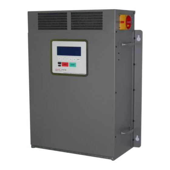
POWERCHARGE™ iHF3 SPECIFICATIONS 480 V Model Numbers PCiHF-10kW-250A-36V PCiHF-10kW-250A-48V PCiHF-10kW-120A-80V Knockout for input wiring Strain reliefs LCD/keypa disconnect switch output cables Optional Ethernet Lift handle Lift handles filter Figure 1: PowerCharge™ iHF3 10 kW Battery Charger features MAN-230000-00 REV B... - Page 8 Specifications for the PowerCharge™ iHF3 480 VAC 10 kW models. PCiHF10kW- PCiHF10kW- PCiHF-10kW - Specifications 250A-48V 250A-36V 120A- 80V 48 V / 250 A Nominal VA Ratings 36 V / 250 A 80 V / 120 A Input Specifications Voltage 400–480 VAC, ±...
-
Page 9: Installation Procedure
INSTALLATION PROCEDURE Charger Installation The following procedure describes proper installation of PowerCharge™ iHF3 series chargers. Charger Unpacking and Inspection Upon receipt of the PowerCharge™, ensure that there is no physical damage to the chassis, the Liquid Crystal Display (LCD)/keypad, the AC disconnect switch, or the DC cables. - Page 10 2. Charger Physical Installation Ensure that the charging area is well ventilated, dry, and clean. There must be at least one foot of spacing between the sides of the charger and any adjacent walls or barriers, and two feet of spacing between the bottom of the charger and the floor or any other obstruction.
- Page 11 b. Post Stand Option The post stand (Figure 4) provides a convenient floor-mount option. The charger mounts to the stand using 1/4-20 hardware provided with the post stand. It is also available with a pogo stick cable management system, providing easy connection to the battery and keeping cables off the floor when not connected.
- Page 12 The post stand should be bolted to the floor using the hole pattern shown (Figure 5). The post-stand base plate has four 0.55-inch diameter holes suitable for ½-inch mounting hardware. Note that the holes in the upper portion of the base plate section must be on the left and right sides of the installation (Figure 7).
- Page 13 The charger can now be lifted onto the mounting studs of the post stand and fastened with the supplied 1/4-20 nuts and flat washers. Figure 7: Assembled post-stand base c. Shelf Stand Option The shelf stand (Figure 8) provides another convenient mounting option. Complete dimensions and clearances are given in Appendix C, page 65 of this manual.
- Page 14 NOTE: Dimension A critical for open shelf mounting Figure 8: Shelf stand Figure 9: Shelf-stand mounting-bolt pattern MAN-230000-00 REV B...
- Page 15 3. Air Filter The charger is equipped with an air filter located in the bottom of the chassis. The air filter needs to be checked on a monthly basis and cleaned if needed. If the charger is mounted less than two feet from the floor or other obstruction, the air filter will need to be checked and cleaned more often.
-
Page 16: Charger Electrical Installation
Charger Electrical Installation WARNING DANGEROUS VOLTAGES AND CURRENTS ARE PRESENT IN THE AC MAINS WHEN ENERGIZED. ONLY TRAINED PERSONNEL SHOULD PERFORM THESE PROCEDURES, USING PROPER EQUIPMENT AND PROCEDURES. VERIFY THAT INPUT AND OUTPUT WIRING ADHERES TO ALL LOCAL SAFETY CODES AND STANDARDS. 1. - Page 17 disconnect switch Figure 12: AC disconnect switch 4. Open the top of the charger by loosening the four mounting screws and lifting the cover off. 5. Push out the knockout (Figure 13) and pass the 480 VAC input power wires through, using the appropriate conduit or strain relief fittings per local and national codes.
- Page 18 AC knockout 480 VAC 3 Figure 13: Charger electrical connection points 8. Verify the line and ground connections of the outlet or junction box/disconnect. 9. With the charger switch OFF, energize the source circuit and verify proper AC voltage at the line side of the charger switch. All line-to-line voltages should be 400–480 VAC ±...
-
Page 19: Operation Procedure
OPERATION PROCEDURE Charger Controls and User Interface Users operate the PowerCharge™ iHF3 series of chargers through each charger’s front panel LCD/keypad (Figure 14). This is the main user interface for viewing and displaying operation and fault messages. It also allows limited charger programming options. (For programming information, see CHARGER PROGRAMMING, page 42 of this manual.) Function keys... -
Page 20: Getting Started
Getting Started The LCD display on the PowerCharge™ iHF3 series presents various screens and SCREEN MESSAGES. 1. Powering the Charger a. Energize the AC mains. b. Turn the AC disconnect switch to the ON position. c. Verify that the LCD display is lit and displays the CONNECT BATTERY screen. - Page 21 2. Starting a Charge Cycle a. Connect the battery to the charger. Once the battery is detected, one of two messages appears on the LCD: The LCD displays the PUSH START TO BEGIN CYCLE screen. 0 4 8 2 0 0 0 4 / 1 5 / 2 0 1 1 1 2 : 0 0 : 0 0 P U S H...
- Page 22 b. If the charger is not set to start automatically, start the charge cycle by selecting the START button on the keypad. A STARTING CHARGE screen appears for a few seconds. S T A R T I N G C H A R G E c.
- Page 23 C Y C L E H H : M M C O M P L E T E D T E M P : X X X F A H R S : X X X X E X I T On this screen appears the elapsed charging time, battery temperature, and total returned amp-hours.
-
Page 24: Charger Main Menu
Charger Main Menu From the charger MAIN MENU screen, access is provided to the following list of items: Charge History Charge Profiles Lifetime Summary Charger Model Recovery Cycle for Sulfated Battery Finish/Equalize Next Cycle ... - Page 25 1. Charge Cycle History a. With either CONNECT BATTERY or PUSH START TO BEGIN CYCLE displayed on the LCD, select F. The CHARGE HISTORY screen appears. M A I N M E N U : C H A R G E H I S T O R Y E X I T E N T E R...
- Page 26 b. Selecting either of the left/right arrow (/) keys displays the second charger history screen. C H 1 9 9 0 4 / 1 5 / 1 1 0 4 : 2 0 A C T I V A T E D P R O F I L E S : S T A T E : X X X X X X X X X X X X X X This second screen lists the following additional information for the selected...
- Page 27 2. Charge Profiles a. While in MAIN MENU, select / until the CHARGE PROFILES screen appears. M A I N M E N U : C H A R G E P R O F I L E S E X I T E N T E R b.
- Page 28 b. Select ENT and a screen summarizing charger lifetime operation appears. F I R S T C H A R G : 0 2 / 0 1 / 1 2 C H R G H O U R S : 1 2 3 4 A M P H O U R S : 1 2 3 4 5 H O U R S : 1 2 3 4...
- Page 29 5. Recovery Cycle for Sulfated Batteries One of the unique features of this charger is the ability to run a safe, tailored recovery cycle for sulfated batteries. This can easily be done through the RECOVERY CYCLE FOR SULFATED BATTERY screen. a.
- Page 30 Selecting / sets the recovery charge current setting in the range of 10 A to 60 A in 5 A increments. Recommended recovery charge current setting is 5 A/100 Ahrs (5% of rated capacity). See Appendix D, page 66 of this manual, for instructions on how to determine the recovery charge current and timer setting.
- Page 31 6. Finish/Equalize Next Cycle a. While in MAIN MENU, select / until the FINISH/EQUALIZE NEXT CYCLE screen appears. M A I N M E N U : F I N I S H E Q U A L I Z E N E X T C Y C L E E X I T...
- Page 32 b. Select ENT to view the network settings. D H C P : E N A B L E P T : 2 0 2 0 I P : 0 . 0 . 0 . 0 M A S K : 2 5 5 . 2 5 5 . 2 5 5 . 2 5 5 G W : 0 .
- Page 33 9. Run PowerTrac™ Diagnostics NOTE: The PowerTrac™ diagnostics option is only valid when connected to a battery with a PowerTrac™ SP+ battery monitoring system installed. a. While in MAIN MENU, select / until the RUN POWERTRAC DIAGNOSTICS screen appears. M A I N M E N U : R U N P O W E R T R A C...
-
Page 34: Troubleshooting
DO NOT ATTEMPT TO SERVICE THE CHARGER! 2. Charger Fault During Operation A fault message is displayed. When contacting the dealer or Power Designers USA LLC, make sure to note the specific fault message that is displayed. This will aid in quick identification of the cause and the appropriate fix for the fault. - Page 35 Select STOP to revert to the IDLE screen. b. Verify the AC connections to the charger. c. Restart the charge cycle by selecting START. d. If the fault persists, contact the dealer or Power Designers USA LLC. MAN-230000-00 REV B...
- Page 36 Verify that the output cables are in good working condition and are properly connected to the battery. d. Restart the charge cycle by selecting START. e. If the fault persists, contact the dealer or Power Designers USA LLC. MAN-230000-00 REV B...
- Page 37 Make sure there are no airflow restrictions at the front or the rear of the charger chassis. d. Check the air filter and clean if necessary. e. Restart the charge cycle by selecting START. f. If the fault persists, contact the dealer or Power Designers USA LLC. MAN-230000-00 REV B...
- Page 38 A primary over current fault produces this message with earlier versions of the firmware Troubleshooting a. Select STOP to revert to the IDLE MODE screen. b. Restart the charge cycle by selecting START. c. If the fault persists, contact the dealer or Power Designers USA LLC. MAN-230000-00 REV B...
- Page 39 Fix, clean, or replace damaged or dirty contacts or cables. c. Select STOP to clear the fault message. d. Restart the charge cycle by selecting START. e. If the fault persists, contact the dealer or Power Designers USA LLC. MAN-230000-00 REV B...
- Page 40 Restart the charge cycle by selecting START. CAUTION g. If an elevated battery temperature is detected, do not restart the charge cycle, or if the fault persists, contact the dealer or Power Designers USA LLC. MAN-230000-00 REV B...
- Page 41 Verify that the programmed parameters values are correct. If not, reset as appropriate. f. Verify that the battery is in good working condition (i.e., no shorted cells). g. If the fault persists, contact the dealer or Power Designers USA LLC. MAN-230000-00 REV B...
-
Page 42: Return Material Process
Call Power Designers USA LLC with a description of the problem. Power Designers USA LLC will attempt to resolve the problem over the phone. If the issue cannot be resolved in this manner, a Return Material Authorization (RMA) form must be completed and submitted to Power Designers USA LLC. -
Page 43: Charger Programming
CHARGER PROGRAMMING Each charger ships preconfigured for the application. To change this programming, please follow these procedures. NOTE: Screens shown are typical of the Palm PDA application. Similarly organized screens, with the same functionality, are found on the Pocket PC and desktop applications. - Page 44 Two Programming Modes are available: Simple Programming can be used to quickly set the basic charge parameters and timers based on the battery voltage and capacity. Detailed Programming allows full use of the charger’s capabilities by manually programming any of the charger settings, parameters, and timers.
- Page 45 The Simple Programming screen contains five programming options. Select the appropriate arrow button to access the desired pull- down menu or type in the appropriate value. Detailed Programming Screen The DETAILED PROGRAMMING screen offers the following functions. Screen Name Programming Function Charger Settings Scan charger factory-set designations and ratings.
- Page 46 The Detailed Programming screen contains buttons for nine programming screens. Select the appropriate button to access the desired programming screen. Charger Settings Screen The CHARGER SETTINGS screen displays the following charger parameters. These parameters are not field-programmable. Parameter Description 1 Charger Model Charger model number.
- Page 47 To view Charger Settings: On the Palm desktop, select PCiHF10kw- the PwrChargeU icon. NOTE: This icon appears as 2311010001 Start PowerChargeUser on the Pocket PC, and PowerChargeUser on the 10000 desktop. Select the Detailed Standalone Programming button and then the Charger Settings button.
- Page 48 Increasing the value of any of the compensation values is rarely necessary. See Appendix E, page 67 of this manual, for a discussion of temperature compensation. Consult Power Designers USA LLC if you have questions. MAN-230000-00 REV B...
- Page 49 To view Battery Settings: On the Palm desktop, select the PwrChargeU icon. NOTE: This icon appears as Start PowerChargeUser on the Pocket PC, and PowerChargeUser on the desktop. Select the Detailed Programming button and then the Battery Settings button.
- Page 50 The following table describes charging modes. Parameter Description Trickle The Trickle charge is a low current charging mode used to recover sulfated or deeply discharged batteries. CV Mode The CV Mode is a constant voltage charging mode that sets the maximum charging voltage during CV operation. Finish Finish activates a finish charge cycle to top off the battery.
- Page 51 Figure 14 illustrates the various charge modes for a typical charge cycle. Equalization voltage Finish voltage Trickle voltage CC finish current Equalization Trickle current current Trickle Finish Equal. Figure 14: Typical charge cycle – charge modes MAN-230000-00 REV B...
- Page 52 Profile 0 Operation The PROFILE 0 OPERATION screen is used to view and program the finish charge operation in Profile 0. The finish mode must be selected on the CHARGE PROFILES screen to be able to select the Custom option. In Default, the finish charge mode is part of every charge cycle.
- Page 53 Profile 1 Operation The PROFILE 1 OPERATION screen is used to view and program the Profile 1 settings. When this profile is active, days of the week, start hour, and duration are selected. Profile 1 is typically set to run on weekends when finish and equalize charging can be conveniently implemented.
- Page 54 System Settings Screens SYSTEM SETTINGS screens are used to view and modify various charger options and system parameters. Parameter Description Defaults First screen Today’s date. Present Date Manuf. date Present Time Present time. Cells Autodetect Autodetect battery nominal voltage (# of cells)— YES or NO.
- Page 55 Notes: 1. Power Designers USA LLC recommends that the default values not be changed. 2. The Precharge High/Low voltage limits function is an optional feature that, if enabled, maintains the charger output voltage between the precharge low and precharge high voltage limits. This eliminates any inrush current or sparking that can result when connecting a battery to the charger.
- Page 56 There are two System Settings screens used to view/program system parameters and various charger options. To view System Settings: On the Palm desktop, select the PwrChargeU icon. NOTE: This icon appears as Start PowerChargeUser on the Pocket PC, and PowerChargeUser on the desktop.
- Page 57 Charge Parameters Screen The CHARGE PARAMETERS screen is used to view and modify the current and voltage settings for the charger. The following table shows typical values for a 500 Ahr fast charge battery. Parameter Recommended Value Example Trickle Current ~3 A /100 Ahrs (Range: 1–600 A) 15 A Trickle Voltage...
- Page 58 To view Charge Parameters: On the Palm desktop, select the PwrChargeU icon. NOTE: This icon appears as Start PowerChargeUser on the Pocket PC, and PowerChargeUser on the desktop. Select the Detailed Programming button and then the Charge Parameters button.
- Page 59 Charge Timers Screen The CHARGE TIMERS screen is used to view and modify the timers for each charge mode. Parameter Description Defaults Total Timer The total timer sets the maximum duration of 9:00 hrs a charge cycle. Range: 0–12:00 hrs Trickle Timer The trickle timer sets the maximum duration 12:00 hrs...
- Page 60 Finish When Volts Per Cell rises by Finish charge less than Finish dV value within time interval Finish dt, finish charging automatically terminates Finish dt Figure 15: Finish charge termination criteria MAN-230000-00 REV B...
- Page 61 To view Timers settings: On the Palm desktop, select the PwrChargeU icon. NOTE: This icon appears as Start PowerChargeUser on the Pocket PC, and PowerChargeUser on the desktop. Select the Detailed Programming button and then the Charge Timers button.
- Page 62 MODEL PowerCharge XP, PowerCharge iHF, REVOLUTION SERIES FOR INDUSTRIAL APPLICATIONS USED IN THE USA & CANADA Power Designers USA LLC (“PD”) hereby warrants each new PowerCharge XP, PowerCharge iHF and REVOLUTION Series battery charger (the “Product”) for industrial application shipped after April 1, 2014 pursuant to the following terms and conditions (the “Product”...
- Page 63 If a “component” or “components” failed due to any cause that the limited warranty does not cover, the owner (Dealer) will be informed of the charges of the repairs before any repairs are performed. If the repairs are approved, PD will repair said product with “new” or “reconditioned to new”...
-
Page 64: Software License Agreement
SOFTWARE LICENSE AGREEMENT This license agreement is a legal agreement between Power Designers USA LLC of Madison, Wisconsin, the author and licensor of the software, and the end user licensee of the software. Installation or other use of this software by the licensee constitutes agreement to all terms and conditions of this license. -
Page 65: Appendix A – Wall Mount Dimensions And Clearances
APPENDIX A – WALL MOUNT DIMENSIONS AND CLEARANCES MAN-230000-00 REV B... -
Page 66: Appendix B – Post Stand Dimensions And Clearances
APPENDIX B – POST STAND DIMENSIONS AND CLEARANCES MAN-230000-00 REV B... -
Page 67: Appendix C – Shelf Stand Dimensions And Clearances
APPENDIX C – SHELF STAND DIMENSIONS AND CLEARANCES MAN-230000-00 REV B... -
Page 68: Appendix D – Recovery Cycle For Sulfated Battery Current And Timer Settings
APPENDIX D – RECOVERY CYCLE FOR SULFATED BATTERY CURRENT AND TIMER SETTINGS When running a recovery cycle for a sulfated battery, use this table as a guide when setting currents and timers. Battery Capacity Current Setting Timer Setting HH:MM 16:45 18:45 20:00 18:45... - Page 69 APPENDIX E – NOTE ON TEMPERATURE COMPENSATION Temperature compensation is critical to maintaining battery life and performance. If the battery temperature is allowed to drift higher or lower than 77°F during normal operation, the charger constant voltage limit should be adjusted to compensate for temperature variations.
-
Page 70: Contacting Power Designers Usa Llc
CONTACTING POWER DESIGNERS USA LLC Power Designers USA LLC 4005 Felland Road, Suite 116 Madison, WI 53718 www.powerdesigners.com sales@powerdesigners.com service@powerdesigners.com Main Office Phone: 608.231.0450 Main Office Fax: 608.231.9979 Service Department: 608.216.9295 Phones are answered between 9 a.m. and 5 p.m., Monday through Friday Central Time.
Need help?
Do you have a question about the PowerCharge iHF3 series and is the answer not in the manual?
Questions and answers