Table of Contents
Advertisement
Quick Links
Advertisement
Table of Contents

Related Manuals for Power Designers REVOLUTION X RVX16


Summary of Contents for Power Designers REVOLUTION X RVX16
- Page 1 RVX16 and RVX24 Models Installation & Operation Manual MAN-000044-00 REV A...
-
Page 2: Table Of Contents
TABLE OF CONTENTS REVOLUTION X SERIES ..................... 1 SAFETY PRECAUTIONS ..................... 2 REVOLUTION SPECIFICATIONS ................5 REVOLUTION RVX16 480VAC ....... 8 PECIFICATIONS FOR THE MODELS 36V REVOLUTION X Chargers Dual Cable Chargers ..........8 48V REVOLUTION X Chargers Dual Cable Chargers ..........9 48V REVOLUTION X Single Cable Chargers ............ -
Page 3: Revolution X Series
REVOLUTION X SERIES The REVOLUTION X Series features very high charge cycle efficiencies and state-of-the-art MOSFET soft-switching technology resulting in lower energy costs, smaller sizes, and lighter weight units. The REVOLUTION X chargers maintain the charging efficiency greater than 90% over the entire charge cycle. -
Page 4: Safety Precautions
SAFETY PRECAUTIONS BEFORE ATTEMPTING TO INSTALL AND OPERATE THE CHARGER, READ THIS MANUAL CAREFULLY This manual contains important instructions for the REVOLUTION series product line that shall be followed during installation and operation of the charger. Only qualified personnel should install, operate, or service this equipment. SAVE THESE INSTRUCTIONS WARNING High Voltages. - Page 5 Do not restrict fan inlets or exhaust outlets. Do not mount the charger in a confined space or where the exhaust air will recirculate. No User Serviceable Parts. If service is required, contact Power Designers Sibex or ...
-
Page 6: Emc Compliance
• Federal Codes 29CFR1926.441 Batteries and Battery Chargers 29CFR1910.305 (j) Wiring Methods, Components and Equipment for General Use OSHA Directive STD 01-08-002, including 29CFR1910.151(c) Medical Services and First Aid; 29CFR1926.50 and 29CFR1926.51, Medical Service and First Aid, and Sanitation, respectively; applicable to electric storage battery charging and maintenance areas. -
Page 7: Revolution Specifications
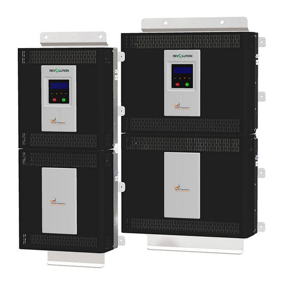
REVOLUTION SPECIFICATIONS Model Numbers (CEC compliant versions add –CEC suffix) RVX16 Model Numbers X16-450A-36V X16-408A-48V-SC X16-495A-36V X16-425A-48V-SC X16-540A-36V X16-585A-36V X16-240A-80V X16-630A-36V X16-260A-80V X16-675A-36V X16-280A-80V X16-700A-36V X16-300A-80V X16-320A-80V X16-340A-48V X16-374A-48V X16-240A-80V-SC X16-408A-48V X16-260A- 80V-SC X16-442A-48V X16-280A-80V-SC X16-476A-48V X16-300A- 80V-SC X16-510A-48V X16-320A-80V-SC X16-544A-48V RVX24 Model Numbers X24-612A-48V... - Page 8 LCD/keypad Output Cables Dual Single Cable Cable Knockout for input wiring Figure 1: RVX16 and RVX24 Battery Charger Features MAN-000044-00 REV A...
-
Page 9: Specifications For The Revolution Rvx16 480Vac Models
Specifications for the REVOLUTION RVX16 480VAC models 36V REVOLUTION X Chargers Dual Cable Chargers X16-450A- X16-495A- X16-540A- X16-585A- X16-630A- X16-675A- X16-700A- SPECIFICATIONS UL Model Number RVX-31.7-700-36 Nominal Volt (V) / 36 V / 450 A 36 V / 495 A 36V / 540A 36V / 585A 36V / 630A... -
Page 10: Revolution X Chargers Dual Cable Chargers
48V REVOLUTION X Chargers Dual Cable Chargers X16-340A- X16-374A- X16-408A- X16-442A- X16-476A- X16-510A- X16-544A- SPECIFICATIONS UL Model Number RVX-32.6-544-48 Nominal Volt (V) / 48 V / 340 A 48 V / 374 A 48 V / 408 A 48 V / 442 A 48 V / 476 A 48 V / 510 A 48 V / 544 A... -
Page 11: Revolution X Single Cable Chargers
48V REVOLUTION X Single Cable Chargers SPECIFICATIONS X16-408A-48V-SC X16-425A-48V-SC UL Model Number RVX-25.5-425-48-SC Nominal Volt (V) / 48 V / 408 A 48 V / 425 A Maximum Current (A) 480VAC, 3-phase±10% Voltage 33.7A rms/ph 35.1A rms/ph Current >0.94 Power Factor Breaker Rating 48V nom. -
Page 12: Revolution X Dual Cable Chargers
80V REVOLUTION X Dual Cable Chargers SPECIFICATIONS X16-240A-80V X16-260A-80V X16-280A-80V X16-300A-80V X16-320A-80V UL Model Number RVX-32.6-320-80 Nominal Volt (V) / 80V /240A 80V /260A 80V /280A 80V /300A 80V /320A Maximum Current (A) INPUT SPECIFICATIONS Voltage 480 VAC, ± 10%, 3-phase 33.7A rms/ph 36.5A rms/ph 39.3A rms/ph... -
Page 13: Revolution X Single Cable Chargers
80V REVOLUTION X Single Cable Chargers X16-240A- X16-260A- X16-280A- X16-300A- X16-320A- SPECIFICATIONS 80V-SC 80V-SC 80V-SC 80V-SC 80V-SC UL Model Number RVX-32.6-320-80-SC Nominal Volt (V) / 80V /240A 80V /260A 80V /280A 80V /300A 80V /320A Maximum Current (A) INPUT SPECIFICATIONS Voltage 480 VAC, ±... -
Page 14: Specifications For The Revolution Rvx24 480Vac Models
Specifications for the REVOLUTION RVX24 480VAC models 48V REVOLUTION X Dual Cable Chargers SPECIFICATIONS X24-612A-48V X24-646A-48V X24-680A-48V UL Model Number RVX-40.8-680-48 Nominal Volt (V) / 48V / 612A 48V /646A 48V / 680A Maximum Current (A) INPUT SPECIFICATIONS 480 VAC, 3-phase ± 10% Voltage 50.6A rms/ph 53.4A rms/ph... -
Page 15: Revolution X Dual Cable Chargers
80V REVOLUTION X Dual Cable Chargers X24-360A- X24-380A- X24-400A- X24-420A- X24-440A- X24-460A- X24-480A- SPECIFICATIONS UL Model Number RVX-49.0-480-80 Nominal Volt (V) / 80V / 360A 80V /380A 80V / 400A 80V / 420A 80V / 440A 80V / 460A 80V / 480A Maximum Current (A) INPUT SPECIFICATIONS 480 VAC, 3-phase ±... -
Page 16: Revolution X Dual Cable Chargers
80V REVOLUTION X Dual Cable Chargers SPECIFICATIONS X24-360A-80V-CN X24-380A-80V-CN X24-400A-80V-CN UL Model Number RVX-40.8-400-80 Nominal Volt (V) / 80V / 360A 80V /380A 80V / 400A Maximum Current (A) INPUT SPECIFICATIONS 480 VAC, 3-phase ± 10% Voltage 50.6A rms/ph 53.4A rms/ph 56.2A rms/ph Current >0.94... -
Page 17: Revolution X Single Cable Chargers
80V REVOLUTION X Single Cable Chargers SPECIFICATIONS X24-320A-80V-SC X24-340A-80V-SC X24-350A-80V-SC UL Model Number RVX-35.7-350-80-SC Nominal Volt (V) / 80V / 320A 80V /340A 80V / 350A Maximum Current (A) INPUT SPECIFICATIONS 480 VAC, 3-phase ± 10% Voltage 45.0A rms/ph 47.8A rms/ph 49.2A rms/ph Current >0.94... -
Page 18: Revolution X Single Cable Chargers
80V REVOLUTION X Single Cable Chargers SPECIFICATIONS X24-320A-80V-SC0 X24-400A-80V-SC0 X24-480A-80V-SC2 UL Model Number RVX-40.8-400-80-SC RVX-49.0-480-80-SC2 Nominal Volt (V) / 80V / 320A 80V /400A 80V / 480A Maximum Current (A) INPUT SPECIFICATIONS 480 VAC, 3-phase ± 10% Voltage 45.0A rms/ph 56.2A rms/ph 67.4A rms/ph Current... -
Page 19: Installation Procedure
INSTALLATION PROCEDURE Charger Installation The following procedure describes proper installation of the REVOLUTION series of chargers. Charger Unpacking and Inspection Upon receipt of a REVOLUTION charger, ensure that there is no physical damage to the chassis, the Liquid Crystal Display (LCD)/keypad, or the DC cables. If any damage is apparent, contact the shipping carrier. -
Page 20: Rv16 Models Installation
RV16 Models Installation • Mount the charger vertically, observing the minimum spacing shown below: Figure 2: RV16 NEC minimum spacing • Ensure that the charging area is well ventilated, dry, and clean. • Do not expose the charger to rain or snow. The charger is NOT designed for outdoor use. - Page 21 • There must be at least 12” of spacing between the sides of the charger and any adjacent walls or barriers, and 12” of spacing between the bottom of the charger and the floor or any other obstruction. This is to allow for service and tool access to the Charger.
- Page 22 1. Preparing the Mounting Area: • The Charger must be mounted vertically as illustrated, using 5/16” hardware. (User provided) The Charger may be directly mounted to masonry or concrete, structural framing channels, or onto the Floor Stand. (purchased separately; see Appendix B) Figure 4: RV16 mounting height Charger should be fastened to the mounting surface using 5/16”...
- Page 23 2. Unpacking the Charger: • Move the Charger’s pallet to the installation area. DO NOT remove Charger from pallet until at the installation area. The Charger IS NOT designed to be transported in any position other than horizontal! • Remove the cardboard box cover from the pallet. DO NOT REMOVE the Shipping Spacer;...
- Page 24 • Remove the 8 screws securing the Charger to the pallet: (Figure 6) Figure 6: RV16 Shipping Screw Removal • Using a hoist, forklift, or other appropriate lifting equipment, attach a chain or strap to the lifting eyes at the top of the charger and pick it up off the pallet. Position the Charger on the installation location and fasten the charger permanently.
-
Page 25: Rv24 Models Installation
RV24 Models Installation • Mount the charger vertically, observing the minimum spacing shown below: Figure 8: RV24 NEC minimum spacing • Ensure that the charging area is well ventilated, dry, and clean. • Do not expose the charger to rain or snow. The charger is NOT designed for outdoor use. - Page 26 • There must be at least 12” of spacing between the sides of the charger and any adjacent walls or barriers, and 12” of spacing between the bottom of the charger and the floor or any other obstruction. This is to allow for service and tool access to the Charger.
- Page 27 1. Preparing the Mounting Area: • The Charger must be mounted vertically as illustrated, using 5/16” hardware. (User provided) The Charger may be directly mounted to masonry or concrete, structural framing channels, or onto the Floor Stand. (purchased separately; see Appendix B) Figure 10: RV24 mounting height •...
- Page 28 2. Unpacking the Charger: • Move the Charger’s pallet to the installation area. DO NOT remove Charger from pallet until at the installation area. The Charger IS NOT designed to be transported in any position other than horizontal! • Remove the cardboard box cover from the pallet. DO NOT REMOVE the Shipping Spacer;...
- Page 29 • Remove the 8 screws securing the Charger to the pallet: (Figure 12) Figure 12: RV24 Shipping Screw Removal • Using a hoist, forklift, or other appropriate lifting equipment, attach a chain or strap to the lifting eyes at the top of the charger and pick it up off the pallet. Position the Charger on the installation location and fasten the charger permanently.
-
Page 30: Charger Electrical Installation
Charger Electrical Installation WARNING DANGEROUS VOLTAGES AND CURRENTS ARE PRESENT IN THE AC MAINS WHEN ENERGIZED. ONLY TRAINED PERSONNEL SHOULD PERFORM THE INSTALLATION, USING PROPER EQUIPMENT AND PROCEDURES. VERIFY THAT INPUT AND OUTPUT WIRING ADHERES TO ALL LOCAL SAFETY CODES AND STANDARDS. 1. -
Page 31: Rv16 & Rv24 Electrical Instructions
RV16 & RV24 Electrical Instructions 3. With a #2 Phillips screwdriver, remove the four 10-32 screws securing the Charger hinge: (Figure 15) Figure 15: RV16 Hinge Screw Locations and Detail 4. Open the Charger hinge. Determine whether the ½” or ¾” conduit hole will be utilized; if ¾”... -
Page 32: Field Wiring Terminals
Figure 16: Hinge Open 5. Pass the 480 VAC input power wires through, using the appropriate conduit or strain relief fittings per local and national codes. Field Wiring GND Stud Terminals Figure 17: RV16 Electrical Connections 6. Crimp a #10 ring tongue terminal to the ground (GND) wire and connect it to the GND terminal (Figure 17). -
Page 33: Operation Procedure
THE CHARGER IS NOW READY FOR OPERATION OPERATION PROCEDURE Charger Controls and User Interface Users operate the REVOLUTION series of chargers through each charger’s front panel LCD/keypad (Figure 18). This is the main user interface for viewing operation and fault messages. It also allows limited charger programming options. -
Page 34: Basic Charge Cycle Operation
Basic Charge Cycle Operation Figure 19: Typical charge cycle – charge modes The typical charge cycle for conventional and opportunity chargers consists of the first four modes (TR, CC, CV, FI) on a daily basis, with all five modes (TR, CC, CV, FI, EQ) occurring on a weekly basis. - Page 35 Finish dv (typically ~5mv/cell) over the length of time defined by the Finish dt (typically ~20 minutes). (Figure 30) Equalize: The equalize mode ensures that all cells of the battery are equally charged. During charge/discharge, the inner and outer cells of the battery will tend to be at slightly different voltage. The equalize mode charges at a low fixed current (~3% of Ahr capacity) for a fixed amount of time (Typically ~3-6 hr), and ensures that all cells are fully and equally charged.
-
Page 36: Getting Started
(AC mains line-to-line) is 480V ± 10%, and matches to within 10VAC or better between phases. • Restart the charger; if the problem persists, contact the Dealer or Power Designers Sibex. MAN-000044-00 REV A... - Page 37 2. Starting a Charge Cycle • Connect the battery to the charger. REVOLUTION Chargers incorporate a detection circuit that distinguishes between a PowerTrac Battery Monitor and a thermistor. If a PowerTrac is detected when the battery is connected, the LCD will momentarily display a screen similar to this: If the Charger has been set up to accept the PowerTrac battery charge parameters, charging of the battery will proceed using the displayed values.
- Page 38 • The charge cycle begins and a screen similar to one of the following, showing the charging operation, appears: The Charging … (XX) field in the upper left corner indicates the active charging mode, the XX will indicate TR for trickle, CC for constant current, CV for constant voltage, FI for finish, or EQ for equalize.
- Page 39 Selecting STOP for the second time stops the charger completely and defaults to the PUSH START screen. Selecting START from the CHARGING STOPPED screen starts a new charge cycle and the screen will again display the charging operation display. • Once the charge cycle has completed, the charger displays the CYCLE COMPLETED screen.
-
Page 40: Charger Main Menu
Charger Main Menu From the charger MAIN MENU screen, access is provided to the following list of screens: • Manual Equalize • Desulfation Cycle • Charge History • Lifetime Summary • Model & SN • Network Settings These screens may only be accessed when the charger is in idle mode (i.e., when either the CONNECT BATTERY or the PUSH START screens are displayed). - Page 41 d. Press ENTER key to save selection and return to the main menu. The LCD display now indicates the Equalization charge is activated with an “E” in the upper right corner of the display, and one of the following displays will be observed, depending on the setup of the Charger.
- Page 42 b. While in MAIN MENU, press / until the DESULFATION CYCLE screen appears. c. Press ENTER to access the recovery cycle set-up screens. The first screen selects the appropriate battery voltage. Pressing / toggles the battery voltage setting. Select the correct voltage and select ENTER.
- Page 43 Pressing / allows adjustment of the charge timer setting in 15-minute increments. The charge timer setting can be set up to 18 hours. Select the desired value, then select ENTER. Next, the START DESULFATION CYCLE screen appears. e. Push START to initiate the desulfation cycle. Once the cycle is complete, a CYCLE COMPLETED message appears.
- Page 44 3. Charge Cycle History a. While in MAIN MENU, press / until the CHARGE HISTORY screen appears. Press the ENTER to access the Charge History screens. b. The first screen that appears is the Charge Cycle history screen as shown below. Users can access the charge history for up to 400 charge cycles, beginning with the most recent charge cycle.
- Page 45 PROFILES lists the profiles activated during the charge cycle. Trickle charge appears as TR, constant current as CC, constant voltage as CV, finish as FI, and equalize as EQ. 4. Lifetime Summary a. While in MAIN MENU, press / until the LIFETIME SUMMARY screen appears. b.
- Page 46 5. Charger Model a. While in MAIN MENU, press / until the MODEL & SN screen appears. b. Pressing the ENTER key displays the charger model number, manufacturing ID, and firmware revision for reference. 6. Network Settings (Ethernet Option Only) a.
-
Page 47: Module Replacement
MODULE REPLACEMENT In the event a module needs to be replaced follow the instructions below. 1. Note the serial number of the module that needs to be replaced from the Main Screen under the Charge History. 2. De-energize and lock out the incoming AC line from the charger. Follow all local safety procedures and PPE guidelines. -
Page 48: Enumerating Installed Modules
ENUMERATING INSTALLED MODULES After a new module is installed into the charger, the charger must be programmed (enumerated) to communicate properly. From the Idle screen, press the Enter key to enter the menu. While in Main Menu, press / until the Model & SN screen appears. 3. - Page 49 6. Press the Up Arrow to select “Yes”. 7. Press the ENTER key to enumerate the modules. The serial numbers of the modules will be displayed; verify the correct number of serial numbers are listed per installed modules. 8. Press the STOP key to exit the menu. MAN-000044-00 REV A...
-
Page 50: Troubleshooting
(AC mains line-to-line) is 480 V ± 10%, and matches to 10 VAC or better. d. If the fault persists, contact the Dealer or Power Designers Sibex. WARNING DANGEROUS VOLTAGES AND CURRENTS ARE PRESENT IN THE AC MAINS WHEN ENERGIZED. - Page 51 The Serial Number of the faulted module is displayed, along with a fault code. When contacting the Dealer or Power Designers Sibex, make sure to note the specific fault message that is displayed. This will aid in quick identification of the cause and the appropriate fix for the fault.
- Page 52 Remove power, disconnect the battery, and verify the AC supply and connections to the charger. c. Restart the charge cycle by connecting the battery and selecting START. d. If the fault persists, contact your dealer or Power Designers Sibex. 2. Output Over-Voltage Fault Possible Causes Battery disconnected while charging.
- Page 53 Verify that the output cables are in good working condition and are properly connected to the battery. c. Restart the charge cycle by selecting START. d. If the fault persists, contact the Dealer or Power Designers Sibex. 4. Charger Over-Temperature Possible Causes Blocked air flow to the charger.
- Page 54 Make sure there are no airflow restrictions to the intake or exhaust of the charger. d. Restart the charge cycle by selecting START. e. If the fault persists, contact the Dealer or Power Designers Sibex. 5. Charger Timeout Faults The screen indicates which timer has caused the problem: TRICKLE CHARGE, CC CHARGE, or CV CHARGE.
- Page 55 Select STOP to revert to the Connect Battery or Push START screens. b. Allow the battery to cool down. c. Restart the charge cycle by selecting START. d. If the fault persists, contact the Dealer or Power Designers Sibex. MAN-000044-00 REV A...
- Page 56 Inspect connections on both charger and battery sides of the battery connector. Verify auxiliary Wire #1 is connected on the positive (red) side of the battery connector. b. If the fault persists, contact the Dealer or Power Designers Sibex. MAN-000044-00 REV A...
-
Page 57: Return Material Process
B. Call Power Designers Sibex with a description of the problem. Power Designers Sibex will attempt to resolve the problem over the phone. If the issue cannot be resolved in this manner, a Return Material Authorization (RMA) form must be completed and submitted to Power Designers Sibex. -
Page 58: Appendix A - Wall Mount Dimensions & Clearances
Appendix A – Wall Mount Dimensions & Clearances RV16 Models Recommended mounting hardware: 5/16”. MAN-000044-00 REV A... -
Page 59: Rv24 Models
RV24 Models Recommended mounting hardware: 5/16”. MAN-000044-00 REV A... -
Page 60: Appendix B - Post Stand Dimensions And Assembly Instructions
Appendix B – Post Stand Dimensions and Assembly instructions RV16 Models MAN-000044-00 REV A... -
Page 61: Rv24 Models
RV24 Models MAN-000044-00 REV A... - Page 62 MAN-000044-00 REV A...
-
Page 63: Appendix C - Note On Temperature Compensation
Appendix C – Note on Temperature Compensation Temperature compensation is critical to maintaining battery life and performance. If the battery temperature deviates from 77 deg. F during normal operation, the charger voltage regulation levels can be automatically adjusted to compensate for temperature variations. The REVOLUTION charger (when used with an optional thermistor) implements two temperature compensation factors expressed in mv/ deg C/cell. -
Page 64: Contact Information
CONTACT INFORMATION Power Designers Sibex 430 N. Suncoast Blvd Crystal River, FL 34429 Tel: 352.795.0101 Fax: 352.564.0772 www.powerdesigners.com sales@powerdesigners.com service@powerdesigners.com Phones are answered between 8 a.m. and 4 p.m., Monday through Friday Eastern Time. After- hours calls are answered by voice mail and returned on the next business day. Questions and comments can also be submitted via fax or email.
Need help?
Do you have a question about the REVOLUTION X RVX16 and is the answer not in the manual?
Questions and answers