Table of Contents
Advertisement
Advertisement
Table of Contents

Related Manuals for FLYGT APP 541


Summary of Contents for FLYGT APP 541
- Page 1 User manual Reset Autamatic Pump Pilot APP 541 APP 541...
-
Page 3: Table Of Contents
Estimate Overflow Flow and Volume..................... 33 Read Operational Data........................36 Read Operational Data........................36 Monitor Status and Alarms......................... 38 Monitor Status on Front Panel......................38 Monitor Alarms in the RTU....................... 40 Monitor Alarms Sent as SMS......................41 Special Alarms........................... 41 APP 541 User manual... - Page 4 Appendix A: RTU Descriptions......................45 List of Alarms .............................45 List of Menus ............................. 47 Appendix B: Tag List..........................60 Appendix B: Tag List.........................60 Appendix C: SCADA Systems......................66 Flygt SCADA System (Aquaview) ....................66 Other SCADA Systems........................68 APP 541 User manual...
-
Page 5: Read This First
Product Overview APP 541 is a pump controller that consists of an I/O module and an operator panel. APP 541 can use a PSTN, GSM, GPRS or radio modem to communicate with a SCADA system, for example AquaView. A special communication module is available for this purpose. - Page 6 The system allows logging, trending and remote commands as well as presenting process data as significant digits, staples, curves, trends, or as symbols varying in colors and sizes. APP 541 User manual...
-
Page 7: Shortguides
2. Repeat for P1 Start counter (7_1), and P1 Run hour (7_2) to P4 Start counter (7_3) and P4 Run hour (7_4) respectively. View and delete alarms 1. Display the Alarm log (1) menu and press OK. 2. Browse the log by repeatedly pressing the Down button. APP 541 User manual... - Page 8 To show menus that are used only during installation or service, select “Yes” in the Show more menus menu (18). The backlight is switched off when the display has been idle for ten minutes. Menu reference chart Legend (Flygt default settings): Always shown: Normally hidden: Shown depending on configuration: APP 541 User manual...
- Page 9 Shortguides (Reference: For a detailed menu list, refer to Appendix A). APP 541 User manual...
-
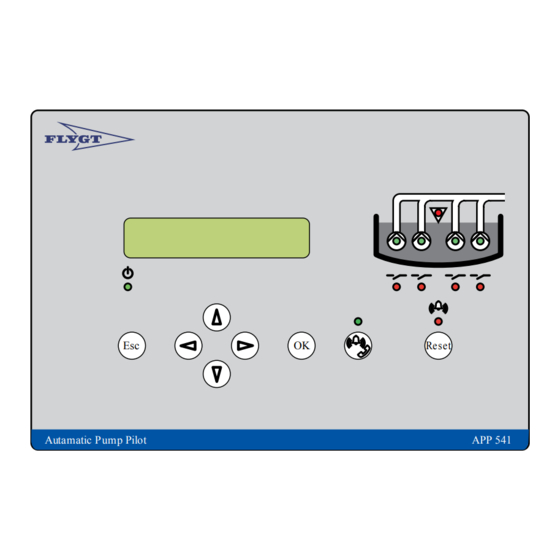
Page 10: Front Panel
Viewing a menu Use the Up arrow to scroll backwards one menu at a time. Use Down arrow to advance one menu at a time. Press OK to display the first menu in a submenu group. APP 541 User manual... - Page 11 Show installation and service menus To show menus that are used only during installation or service: • Select "Yes" in the Show more menus menu (18). • If the password function is in use, enter the password instead. APP 541 User manual...
- Page 12 The display language is changed in the Language menu (20_). Look for the symbol. It is shown in the top-left corner of the Language menu. To show parameter values in U.S. units, select the language "English US". APP 541 User manual...
-
Page 13: Configure Basics
Keep in mind: If the modules form a local network, the default Base IP address is sufficient. 2. If necessary, specify a new IP communication timeout in the IP timeout menu (17_6_3). Keep in mind: the default value is appropriate for most installations. APP 541 User manual... -
Page 14: Configure Analogue Level Sensor
2. Stop level 1 3. Stop level 2 4. Stop level 3 5. Stop level 4 6. Start level 1 7. Start level 2 8. Start level 3 9. Start level 4 10. High level Function: Analogue levels APP 541 User manual... - Page 15 • High level menu (2_9). • Low level menu (2_10). Disable a pump 1. Set a start level to "0". 2. Set the corresponding stop level to "0". Disable low level block Set low level alarm limit to "0". APP 541 User manual...
-
Page 16: Configure I/O
• The pump is blocked. It remains blocked as long as the thermal contact remains open. • A high temperature alarm is generated. Exception: EX-mode In EX-mode, General purpose input 1–4 are automatically assigned as manual mode inputs for pump 1–4. (Reference: “EX-classified Environment”). Exception: Three pumps or less APP 541 User manual... -
Page 17: Other Inputs
Not connected Controlled automatically Motor Protection A pump can use motor protection. Before using this function This function requires that the motor protection is connected to the Motor protector input for the pump. Function: Motor protection APP 541 User manual... -
Page 18: Configure Outputs
When an alarm is generated, alarm equipment such as a lamp or a siren can be turned on as well. Before using this function This function requires that the alarm equipment is connected to the common alarm output. Function: Common alarm output APP 541 User manual... -
Page 19: Other Outputs
Select “Flushing valve” in the Function output 4 menu (17_7_1). 1. Specify the number of pump cycles between each flushing in the Flushing interval menu (13_17). 2. Specify how long time to flush in the Flushing time menu (13_18). Disable flushing APP 541 User manual... - Page 20 Function: Automatic reset 1. RTU waits three minutes for the protection to cool. 2. RTU tries to reset the motor protection once.Result: The table shows possible results. If reset... Then... is successful. pump can now restart. APP 541 User manual...
- Page 21 Configure motor protection reset 1. Select “Motorprotect. reset” in the Function output 4 menu (17_7_1). 2. In the Auto reset menu (16_3), select: • "Yes" to enable automatic reset. • "No" to disable automatic reset. APP 541 User manual...
-
Page 22: Extended Configuration
This function should be enabled when the RTU is used in an EX-classified environment. Function: EX-mode When no liquid is detected in the sump, all pumps are blocked. The starting method will not matter, that is, any manual start attempt, maintenance run, or remote start command will be blocked. APP 541 User manual... -
Page 23: Trim Pump Control
Set maximum runtime to "0". Maintenance run A pump that stands still for a long time can be run automatically with regular intervals. This is useful to keep the mechanical seals in the pump in shape. Function: Maintenance run APP 541 User manual... - Page 24 No pump No pump Pump 4 Pump 4 Pump 4 Configure pump alternation 1. Select "On" in the Pump alternation menu (13_7). 2. Specify number of alternating pumps in the Alternating pumps menu (13_8). Disable pump alternation APP 541 User manual...
-
Page 25: Configure Extra Functions
2. Specify the rain alarm limit for a 5 minute period in the Rain alarm 5min menu (9_1). 3. Specify the rain alarm limit for a 24 hour period in the Rain alarm 24h menu (9_2). APP 541 User manual... -
Page 26: Configure Communication
4. Type in the initialization string: E.g. AT&F E0V0 &K3 &D2\\N3 %E0 S36=3 S0=0 and press Enter. NOTICE: The initialization string must be permanently stored in the modem. Either: • Append "&W" to the initialization string, • Type "AT&W" after entering the initialization string. APP 541 User manual... -
Page 27: Configuration
In the SCADA system, the station number is a unique number for the RTU. When fixed communication is used, the station number and fixed line id both have the same value in Aquaview. (15_1) GPRS modem Communication using a GPRS modem APP 541 User manual... - Page 28 Otherwise set this value to the same as the value used in the pre- configuration of the modem. Parity COM1 (15_1 None, Even or Use the same setting as in the communication equipment. APP 541 User manual...
- Page 29 1200-115200 bps If your modem supports autobauding, set this as high as possible to get the best communication performances. Otherwise set this value (15_13) to the same as the value used in the initialization string for the modem. APP 541 User manual...
- Page 30 Only applicable when alarm handling using SMS is selected. Telephone no. SMS 5 Telephone number to SMS receiver. The telephone number is required for alarm handling to more than one SMS receiver. (15_7) Only applicable when alarm handling using SMS is selected. APP 541 User manual...
-
Page 31: Configure Alarm Handling
Alarm is only local in the RTU. Alarm is sent to: SCADA system according to its D-alarm time frame, SMS receivers according to the D-alarm time frame in the RTU. Alarm is not recorded. For future use. APP 541 User manual... -
Page 32: Alarms Sent To Scada System
The RTU can send SMS with alarms to one recipient at a time or to all at once. Function: Alarm acknowledgement time Phase Description RTU sends an SMS with an alarm to a recipient. Result: RTU receives an acknowledgement Result: RTU receives no acknowledgement within within specified time. specified time. APP 541 User manual... -
Page 33: Special Alarms
Before using this function Configure a General purpose input as personnel alarm input. Restriction NOTICE: The personnel alarm always has alarm priority A and cannot be prevented from being sent. Function: Personnel alarm APP 541 User manual... - Page 34 • Work time is restarted. • Common alarm outputs are set to passive. Configure the personnel alarm: 1. Enter a time in the Work time menu (14_5). 2. Enter a time in the Warning time menu (14_6). APP 541 User manual...
-
Page 35: Measure Flow Rate And Capacity
Types of overflow monitoring Overflow calculations starts when: • Overflow activates the overflow sensor, • Sump level exceeds a specified overflow level. Keep in mind: Overflow level is only relevant if an analogue level sensor is used. APP 541 User manual... - Page 36 3. Specify the weir discharge coefficient in the Discharge coeff. menu (8_3). Reference: Spillway supplier.Example. A typical value is 0.58. 4. Specify a range in the Overflow range menu (8_4) 5. Specify a width in the Weir width menu (8_5). APP 541 User manual...
- Page 37 3. Specify a range in the Overflow range menu (8_4). 4. Specify overflow 1 in the Overflow segment 1 menu (8_6). 5. Repeat Step 4 for any other known overflow flow. Keep in mind. Enter "0" not to use a level. APP 541 User manual...
-
Page 38: Read Operational Data
Calc. capacity P1 – P4 12_1 – Capacity for Pump 1–4. 12_4 Reset operational data 1. View the relevant operation menu. Example: P1 start counter menu. 2. Press OK. Result: Menu window shows "Reset value? No". APP 541 User manual... - Page 39 Read Operational Data 3. Press the Up arrow. Result: Menu window shows "Reset value? Yes". 4. Press OK. Result: Data is reset. APP 541 User manual...
-
Page 40: Monitor Status And Alarms
High level switch, High level alarm limit for analogue sensor There is feedback from the pump The pump is running. relay. Green There is a pump fault. Possible causes: High temperature in pump Motor protection has tripped. APP 541 User manual... - Page 41 The alarm is acknowledged. No active alarms An alarm is being sent to: SCADA system, SMS receivers. Flashing green RTU is set to send alarms to: SCADA system, SMS receivers. Green No alarm is sent outside the RTU. APP 541 User manual...
-
Page 42: Monitor Alarms In The Rtu
2. Press the Up or Down arrow to select either: • "Current" – only the current alarm will be deleted. • "All" – all alarms will be deleted. 3. Press OK. Result: The text "Log cleared" is displayed. Close the Alarm log Press Esc. APP 541 User manual... -
Page 43: Monitor Alarms Sent As Sms
• Reply to the SMS Keep in mind: No text is required. Special Alarms Acknowledge Presence The personnel alarm function is activated by a selector switch, usually a light switch in the pump station. Function: Personnel alarm APP 541 User manual... - Page 44 You can try to reset a tripped motor protection manually. Reset motor protection manually • Press Reset on the RTU front panel, • Use remote control from the SCADA system. Keep in mind: Reset can only be done when the pumps are stopped. APP 541 User manual...
-
Page 45: Miscellaneous
• After 10 minutes the RTU will automatically revert to normal operation. Menu value Function Result None The RTU is in normal operation. Digital inputs The states of the digital inputs are displayede.g. 1001100100000000 LED output Flashes at 1 second interval. Common alarm output APP 541 User manual... - Page 46 Select the program in the Diagnostic program menu (17_8). Reset RTU to default settings 1. Select "Yes" in the Flygt default menu (17_9). Result: RTU restarts, and the text "Restart" is shown in the display. 2. Wait until the restart is complete, and the text have disappeared.
-
Page 47: Appendix A: Rtu Descriptions
There is no response signal from pump 2. The pump has probably not started despite activation of the power relay. No response P3 No response P3 There is no response signal from pump 3. The pump has probably not started despite activation of the power relay. APP 541 User manual... - Page 48 The pump 4 has exceeded the maximum allowed run time. The pump is time blocked by this alarm.See also the Max run time set-point. 8505 Sensor Fault Sensor Fault An error in the analogue sensor has been detected. The measured level is outside the sensor range. APP 541 User manual...
-
Page 49: List Of Menus
High rainfall 24 h The RTU has calculated a rainfall higher than the rain alarm limit for 24 hours. List of Menus Menu name Specification Description Alarm log Writable Alarm log. Level ft Read only Level indication. APP 541 User manual... - Page 50 High current alarm limit for second pump. current (A) P2 low current A WritableCentral System TextP2 low Low current alarm limit for second pump. current (A) Current range P2/P4 Writable Current transformer range for pump 2 and 4 APP 541 User manual...
- Page 51 Overflow segment 2 used by the manual calculation method to TextOverflow segment 2 (GPM) calculate overflow flow and overflow volume. Overflow segment 3 WritableCentral System Overflow segment 3 used by the manual calculation method to TextOverflow segment 3 (GPM) calculate overflow flow and overflow volume. APP 541 User manual...
- Page 52 Enter the nominal capacity of P1. Used for capacity alarms. P1GPM TextNominal capacity P1 (GPM) 12_1_2 Capacity div. P1GPM WritableCentral System Divergation limit for high and low capacity alarms. Uses nominal TextCapacity divergation limit P1 capacity +/- this channel. (GPM) APP 541 User manual...
- Page 53 Writable Alternative0 = Off The Alternation menu specifies the pump operating sequence. 1 = OnCentral System TextPump alternation 13_8 Alternating pumps WritableCentral System Specifies the number of pump to use in the alternation. TextNumber of alternating pumps APP 541 User manual...
- Page 54 14_9 D-alarm start time Writable Interval0 - 0 The start time for dialling out alarms with priority D. 14_10 D-alarm end time Writable Interval0 - 0 The stop time for dialing out alarms with priority D. APP 541 User manual...
- Page 55 Alarm text input 4 WritableCentral System TextAlarm Alarm text to use for general input 4. text input 4 14_15_ Alarm text input 5 WritableCentral System TextAlarm Alarm text to use for general input 5. text input 5 APP 541 User manual...
- Page 56 Telephone no. SMS 3 WritableCentral System Telephone number to SMS receiver. The telephone number is TextTelephone SMS 3 required for alarm handling to more than one SMS receiver.Only applicable when alarm handling using SMS is selected. APP 541 User manual...
- Page 57 Access point name. (part 2)Applies to communication with GPRS only 15_21 Max buffer sizebytes Writable Limits the data size when collecting trend. General... Read only Menu group for general set-points 16_1 Date and time Writable Setting of date and time. APP 541 User manual...
- Page 58 516 = General input 617 = General input 718 = General input 17_4 Common alarm... Read only Menu group for common alarm output 17_4_1 Common alarm Writable Alternative0 = Type of common alarm output.Continuous or pulsating. Continuous1 = Intermittent APP 541 User manual...
- Page 59 P1 manual2 = Power failure3 = External alarm4 = Blocking5 = Personnel6 = Rain meter7 = Overflow8 = Low level float9 = High level float10 = High temp. P111 = P1 Spare alarmCentral System TextFunction general input APP 541 User manual...
- Page 60 P3 auto2 = Power failure3 = External alarm4 = Blocking5 = Personnel6 = Rain meter7 = Overflow8 = Low level float9 = High level float10 = High temp. P311 = P3 Spare alarmCentral System TextFunction general input APP 541 User manual...
- Page 61 ¤ Language Writable Alternative0 = English1 = Select display language. Deutsch2 = Nederlands3 = Français4 = Dansk5 = Svenska6 = Norsk7 = Español8 = Magyar9 = Suomi10 = Italiano11 = PycckNN12 = Polski13 = English APP 541 User manual...
-
Page 62: Appendix B: Tag List
Appendix B: Tag List Appendix B: Tag List Appendix B: Tag List APP 541 User manual... - Page 63 Appendix B: Tag List APP 541 User manual...
- Page 64 Appendix B: Tag List APP 541 User manual...
- Page 65 Appendix B: Tag List APP 541 User manual...
- Page 66 Appendix B: Tag List APP 541 User manual...
- Page 67 Appendix B: Tag List APP 541 User manual...
-
Page 68: Appendix C: Scada Systems
9. Overflow flow 10. Overflow volume 11. Max level 12. High level 13. Start level 14. Stop level 15. Low level 16. Alarm handling (local/remote) 17. P1 capacity 18. P1 current 19. P1 starts 20. P1 run time APP 541 User manual... - Page 69 • 9:00 AM - 4:00 PM • 4:00 PM - 12:00 AM Available data is listed in the table below. The RTU stores this data for 31 days. Text1 Text2 Text3 Description Run time h:min Running time pump 1. APP 541 User manual...
-
Page 70: Other Scada Systems
• Keep in mind: Use the same trend resolution in the RTU as in AquaView. Other SCADA Systems The figure on next page shows a status view example using Citect. Communication Methods The RTU supports several communication methods for communicating with other SCADA systems: APP 541 User manual... - Page 71 Block all pumps Reset Reset motor protection Resume to auto Functions will no longer be controlled remotely Keep in mind: If communication to the RTU is lost, the pump will return to automatic mode after 30 seconds. APP 541 User manual...
- Page 72 Caller id field in the SCADA system must correspond to the caller id sent from the RTU. If caller id is not supported by the SCADA system, it will request a PLC_ID from the RTU. Polls the RTU for active alarms. Acknowledges the alarms. APP 541 User manual...
- Page 73 When a GSM modem is used, GSM-network delays may cause the SCADA system to timeout. To solve this: • Increase the timeout setting in the SCADA system, • Decrease the number of registers/IO in each request. APP 541 User manual...
- Page 76 Xylem |’zīləm| 1) The tissue in plants that brings water upward from the roots 2) A leading global water technology company We're 12,000 people unified in a common purpose: creating innovative solutions to meet our world's water needs. Developing new technologies that will improve the way water is used, conserved, and re-used in the future is central to our work.
Need help?
Do you have a question about the APP 541 and is the answer not in the manual?
Questions and answers