Table of Contents
Advertisement
Advertisement
Table of Contents

Related Manuals for FLYGT APP700


Summary of Contents for FLYGT APP700
- Page 1 Installation Hardware for APP700 and APX700...
-
Page 3: Table Of Contents
Modem types ............................17 General instruction..........................17 Communication status LED......................18 Test the Connections...........................19 Test communication..........................19 Test level sensor signal........................19 Test digital inputs..........................19 Test supply voltage........................... 19 Technical Data............................20 Hardware Data...........................20 Electrical Data............................ 21 Standards............................23 Hardware for APP700 and APX700 Installation... -
Page 4: General Safety Information
24VDC signal wire separate from high voltage wire (120VAC and above) in wire trays, shielding cable that must remain in the same cable trays as high voltage wire, and always using shielded cable for analog signals. Hardware for APP700 and APX700 Installation... -
Page 5: Warranty
The use of other parts can invalidate any claims for warranty or compensation. Warranty claim For warranty claim, contact your Xylem representative. Support Xylem only supports products that have been tested and approved. Xylem will not support unapproved equipment. Hardware for APP700 and APX700 Installation... -
Page 6: Warning Symbols
• considerable damage to property Caution! Risk of causing • injury to people, or • damage to property On the product This symbol may occur on Xylem electric products, warning for presence of a dangerous voltage. Hardware for APP700 and APX700 Installation... -
Page 7: Mount The Unit
Make an opening for the operator panel in the panel door using a jigsaw . Place the operator panel in the opening. Fit the washers and nuts, and tighten them firmly. Dimensional drawing: Operator panel This is a dimensional drawing of the operator panel. 10.08 in Figure 1 Hardware for APP700 and APX700 Installation... -
Page 8: Mount The I/O Unit
• Hang the I/O unit on the screws. • Tighten the screws firmly. • Connect the cable supplied between the operator panel and the I/O unit. • Secure the cable so that it will not be crimped. Hardware for APP700 and APX700 Installation... -
Page 9: Dimensional Drawing: I/O Unit
This is a dimensional drawing of the I/O unit. 11.65 in 10.87 in 11.65 in Figure 3 Mount the level sensor For instructions on how to mount the level sensor, see separate level sensor manual. Hardware for APP700 and APX700 Installation... -
Page 10: Avoid Electric And Magnetic Field Disturbances
The overvoltage protection for the mains power supply should be connected in series with the mains power supply connection. The overvoltage protection for the telecommunications cable should be in series with the telecommunications cable. Hardware for APP700 and APX700 Installation... -
Page 11: Illustration
Avoid Electric and Magnetic Field Disturbances Illustration The picture to the right in this illustration shows how to avoid electric and magnetic disturbances when installing the RTU system. Figure 4 Hardware for APP700 and APX700 Installation... -
Page 12: Detailed Connection Drawing
Detailed Connection Drawing Detailed Connection Drawing Illustration This is a detailed connection drawing of the terminals. Figure 5 Hardware for APP700 and APX700 Installation... -
Page 13: Connect Inputs And Outputs
Connect the analog inputs according to • Connection drawings, and • Terminals Connect the functional earth (ground). Connection drawings These are the connection drawings for analog inputs. Passive sensor: Figure 6 Active sensor: Figure 7 Hardware for APP700 and APX700 Installation... -
Page 14: Connect Digital Inputs
Connect the digital inputs according to the following instructions: • Connect active sensor,or • Connect passive sensor,and • Terminals Connect active sensor Follow this connection drawing to connect active sensors to the digital inputs. Figure 8 Hardware for APP700 and APX700 Installation... - Page 15 This table gives an overview of the terminals for digital inputs. Table 7 Terminal Input signal no./Description +01/–02 Internal 24V DC power supply to digital input signals. +03/–04 +05/–06 +07/–08 +09/–10 +11/–12 +13/–14 +15/–16 +17/–18 +19/–20 +21/–22 +23/–24 +25/–26 +27/–28 +29/–30 +31/–32 Hardware for APP700 and APX700 Installation...
-
Page 16: Connect Digital Outputs
This table gives an overview of the terminals for digital outputs. Table 8 Terminal Output signal no. Type/Rated for 53/54 Relay output 2A, 250V, AC/DC 55/56 57/58 59/60 61/62 63/64 65/66 Semiconductor output 100 mA, 250V AC/DC 67/68 Hardware for APP700 and APX700 Installation... -
Page 17: Connect Remote I/O
Remove the cover of the I/O Panel and install a SIOX Expansion Card inside the I/O Panel, making sure all pins from the SIOX Expansion Card are connected to the header on the I/O Panel. Reinstall the cover. Connect external I/O units to terminals 37–38. Figure 11 Hardware for APP700 and APX700 Installation... -
Page 18: Connect The Power Supply
(ground) bus bar in the panel. The conductor area of the cable between the overvoltage protection and earth (ground) should be 6-10 mm Hardware for APP700 and APX700 Installation... -
Page 19: Connect The Modem
Table 12 Step Action Connect the modem to COM port 1, 3 or 4. Connect the modem power supply. Reference: See respective modem manual for more information on how to connect the specific modem. Hardware for APP700 and APX700 Installation... -
Page 20: Communication Status Led
Table 13: This table shows the different lights of the communication status led and what the colors mean. Color Description Green The RTU has received data from the COM port The RTU has sent data to the COM port Hardware for APP700 and APX700 Installation... -
Page 21: Test The Connections
Follow these steps to test supply voltage. Table 16 Step Action Check OK Check the power supply unit connections. Measure the supply voltage at the terminal block and check that it is within the specified range. Hardware for APP700 and APX700 Installation... -
Page 22: Technical Data
Specification Size (L x W x H) 11.65 x 10.67 x 2.44 in Weight (total) 4.41 lb Mounting Wall Connectors 1 pc. DB 37 Wire terminals 68 pc., screw locked Unit standard IP 20 Hardware for APP700 and APX700 Installation... -
Page 23: Electrical Data
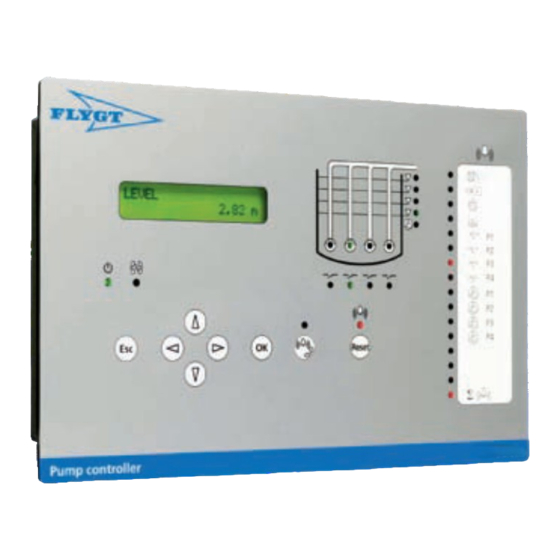
This table shows the electrical data of the digital outputs. Table 22 Type Item Specification Isolation Individually isolated Total number Relay Number Type Normally open, unprotected Max load 2 A, 250V AC/DC Solid state Number Hardware for APP700 and APX700 Installation... - Page 24 Table 25: This table shows the number of push buttons and indications of the interface for the different versions. Version Push buttons Alarm indications Pump well RTU status indications indications APP 721 Pump controller APP 731 Pump controller APP 741 Pump controller Hardware for APP700 and APX700 Installation...
-
Page 25: Standards
Table This table shows the approved standards for the unit. Table 27 Standard Number EMC Emission Standard EN 61000-6-4 EMC Immunity Standard EN 61000-6-2 EN 60947-1 C22.2 No. 14-95 UL Recognized File Number E302902 Hardware for APP700 and APX700 Installation... - Page 28 Xylem |’zīləm| 1) The tissue in plants that brings water upward from the roots 2) A leading global water technology company We're 12,000 people unified in a common purpose: creating innovative solutions to meet our world's water needs. Developing new technologies that will improve the way water is used, conserved, and re-used in the future is central to our work.
Need help?
Do you have a question about the APP700 and is the answer not in the manual?
Questions and answers