
Subscribe to Our Youtube Channel
Related Manuals for Adlee Powertronic Adleepower AS1


Summary of Contents for Adlee Powertronic Adleepower AS1
-
Page 1: Instruction Manual
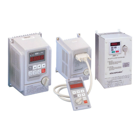
ADLEEPOWER INSTRUCTION MANUAL GENERAL-PURPOSE INVERTER THANK YOU VERY MUCH FOR YOUR PURCHASE OF ADLEE INVERTER AS SERIES. PLEASE READ THIS INSTRUCTION MANUAL BEFORE INSTALLATION OF THE INVERTER. - Page 2 PREFACE This general-purpose inverter made by ADLEE Powertronic., Ltd. Read this instruction manual throughly before operation. This manual will be helpful in the installation, parameter setting, troubleshooting, and daily maintenance of the AC motor drives. To guarantee safe operation of the equipment, read the following safety guidelines before connecting power to the AC drives.
- Page 3 RECEIVING CAUTION * Do not install or operate the driver which is damaged or has missing parts. Failure to observe this caution may result in personal injury or equipment damage. INSTALLATION CAUTION * Lift the cabinet by the base. When moving the unit, never lift by the front cover.
- Page 4 CAUTION * Verify that the driver rated voltage coincides with the AC power supply voltage. Failure to observe this caution can result in personal injury or a fire. * Do not perform a withstand voltage test of the driver. It may cause semi-conductor elements to be damaged. * To connect a braking resistor, follow in APPENDIX A.
-
Page 5: Maintenance And Inspection
CAUTION * Since it is easy to change. operation speed from low to high speed, verify the safe working range of the motor and machine before op- eration. Failure to observe this caution can resuit in personal injury and machine damage. * Do not change signals during operation. - Page 6 CAUTION * The control PC board employs CMOS ICs. Do not touch the CMOS elements by hand. They are easily damaged by static electricity. * Do not connect or disconnect wires or connectors while power is applied to the circuit. Failure to observe this caution can result in personal injury.
-
Page 7: Table Of Contents
CONTENTS 1. RECEIVING 2. SPECIFICATIONS 3. DIMENSION DRAWINGS 4. INSTALLATION 5. DESCRIPTION OF TERMINALS 6. DIGITAL OPERATION PANEL 7. FUNCTIONS DESCRIPTION 8. DISPLAY ERROR CODES 9. HARDWARE PROTECTIVE FUNCTIONS 10. PRECAUTIONS 11. TROUBLESHOOTING 12. APPLICATION 13. INVERTER SELECTION 14. APPENDIX A. -
Page 8: Receiving
1. RECEIVING This AS series AC drive has gone through rigorous quality control tests at the factory before shipment. After receiving the AC drive, please check for the following : (1) No damage is found on each product after shipping. (2) The product is as ordered (check the nameplate, voltage and fre- quency). -
Page 9: Specifications
2. SPECIFICATIONS (1) Single phase input port M o d e l Voltage 1£p110VAC ¡Ó10% 1£p220VAC ¡Ó10% Model No AS1-104 AS1-107 AS2-104 AS2-107 AS2-115 AS2-122 AS2-137 Input Frequency 50HZ ~ 60HZ ¡Ó 10% Output Voltage 3£p 220VAC Output Frequency 0.5 ~ 400HZ / 0.5 ~ 2000HZ (High frequency) O u t p u t 11 A 17 A... - Page 10 (2) 3 Phase input port Model Voltage 3£p 220VAC ¡Ó 10% 3£p 380/440VAC ¡Ó10% Model No AS2-304 AS2-307 AS2-315 AS2-322 AS2-337 AS4-307 AS4-315 AS4-322 AS4-337 Input Frequency 50HZ ~ 60HZ ¡Ó10% Output Voltage 3£p 220VAC 3£p 380/440VAC Output Frequency 0.5 ~ 400HZ / 0.5 ~ 2000HZ (High frequency) Output 11 A 17 A...
-
Page 11: Dimension Drawings
3. DIMENSION DRAWINGS Unit : mm Fig 1... - Page 12 Unit : mm Fig 2...
- Page 13 Unit : mm FUNC PROG STOP INDUCTION MOTOR DRIVES ¡I DANGER HAZARDOUS HIGH VOLTAGE Securely ground(earth) both the inverter(FG) and motor. WARNING Disconnect all power and wait 5 min.before servicing.May cause electric shock. ADLEEPOWER MOTOR INPUT L1 L2 Fig 3...
-
Page 14: Installation
4. INSTALLATION Inadequate environment around installation site and installation surface can result in damage to the inverter. Before operating the AS series inverter, please check the following points : (1) Avoid high temperature, high humidity, easy-to-dew ambient envi- ronment. Don¡¦ t expose to dust or dirt, corrosive gas, and coolant mist, and direct sunlight. - Page 15 4 cm 5 cm 5 cm AIR FLOW...
-
Page 16: Description Of Terminals
5. DESCRIPTION OF TERMINALS (1) Main circuit connection diagram L1 L2 L3 U 60O80W GROUND External braking resistor MOTOR Refer to the appendix A POWER SOURCE Main circuit terminal Symbol Description Terminal name Ground Ground(Earth) Terminal (L1,L2) Single Phase Connect power supply (L1,L2,L3) 3 Phase Terminals connected Inverter output... - Page 17 (2) Control circuit terminal VCC FA1 FA2 GND B C FWDREV CF1 CF2 FT1 FT2 MT H COM Fault Relay Contact rating 1A 240VAC 1A 30VDC Symbol Multi function analog terminal Analog source Power source +5V of analog terminals Free analog terminal 1 See CD44 &...
- Page 18 (3) Description of Hardware setting VCC FA1 FA2 GND B C FWD REV CF1 CF2 FT1 FT2 MT H COM 3-1 DIP Switch setting (SW1) Setting FA1 Setting FA2 FA1 : 0 - 10V FA2 : 0 - 10V 1 2 3 4 1 2 3 4 FA1 : 0 - 5V FA2 : 0 - 5V...
- Page 19 (4) WIRING THRY 4-1 Wiring of main circuit Filter (L3) 4-2 Wiring equipments Select the wiring equipment and wiring size, refer to the table below. 1. On the input power side, a molded case circuit breaker (MCCB) to protect inverter primary wiring should be installed. 2.
- Page 20 4-3 Surge absorber In order to prevent malfunction, provide the surge absorber on the coils of the electromagnetic contactors, relays and other devices which are to be used adjacent of the inverter. 4-4 Cable size and length If the inverter is connected to a distant motor (especially when low frequency is output), motor torque decreases because of voltage drop in the cable.
- Page 21 4-6 Wiring and cautionary points A. Main circuit 1. Connect the cables of the power supply side to the U, V and W output terminals for the motor. 2. Don t connect any electromagnetic contactor between the ’ inverter and motor. If it is inevitable, turn on the contactor when both the inverter and motor are both at stand still.
-
Page 22: Digital Operation Panel
6. DIGITAL OPERATION PANEL LED Operating Indication Digital Indication LED Operating Indication FUNC PROG STOP Digital Indication FUNC PROG STOP Operation key Key function Description FWD RUN Forward run Commands forward run REV RUN Reverse run Commands reverse run Cursor SHIFT Select the digit movement... -
Page 23: Functions Description
7. FUNCTIONS DESCRIPTION DISPLAY STANDARD FUNCTION NAME ORDER SETTING VALUE U : 60HZ ¡¸ CD00 First speed setting E : 50(B03) / 0(B04) CD01 Parameter lock CD02 Acceleration time 1 10 Sec CD03 Deceleration time 1 10 Sec CD04 Jogging frequency CD05 Start frequency 0.5HZ... - Page 24 CHANGEABLE USER OF SETTING UNIT REMARK SETTING VALUE 0 ~ 400 HZ 0.01 HZ 0 or 1 ---- 0 = lock 1 = Unlock 0.1 ~ 6000 Sec 0.1 Sec 0.1 ~ 6000 Sec 0.1 Sec 0 ~ 400 HZ 0.01 HZ 0.5 ~ 30 HZ 0.01 HZ...
- Page 25 DISPLAY STANDARD FUNCTION NAME ORDER SETTING VALUE CD18 V/F pattern setting CD19 DC braking time 1 Sec CD20 DC braking power CD21 Torque boost CD22 Second speed setting 20 (B03) / 0 (B04) CD23 Third speed setting 30 (B03) / 0 (B04) CD24 Fourth speed setting 40 (B03) / 0 (B04)
- Page 26 CHANGEABLE USER OF SETTING UNIT REMARK SETTING VALUE 0 : Constant torque 0 ~ 2 ---- 1 : (Frequency) 2.0 2 : (Frequency) 3.0 0 ~ 25 Sec 0.1 Sec 0 ~ 250 1.00 0 ~ 25% 0.1 % 0 ~ 400 HZ 0.01 HZ 0 ~ 400 HZ 0.01 HZ...
- Page 27 DISPLAY STANDARD FUNCTION NAME ORDER SETTING VALUE CD38 Errors record 2 NONE CD39 Errors record 3 NONE CD40 Clear errors record CD41 HZ / RPM Display CD42 FT1 Multi-Function Terminal 1 CD43 FT2 Multi-Function Terminal 2 CD44 FA1 Free Analog Terminal 1 CD45 FA2 Free Analog Terminal 2 CD46...
- Page 28 CHANGEABLE USER OF SETTING UNIT REMARK SETTING VALUE ---- 0 or 1 ---- 1 = Clear 0 or 1 ---- 0 = HZ Display 1 = RPM Display 0 or 1 ---- 0 ~ 15 ---- RESET SEE 3-2 JP1 0 ~ 15 ---- 0 ~ 15...
- Page 29 7-1. Function setting Before starting test run, check carefully the following points : (1) Be sure to connect the power supply to L1, L2, L3 (input terminals) and the motor to U.V.W. (output terminals). (Wrong connections will damage the inverter.) (2) Check that the input power supply coincide with input voltage and input phase of the inverter.
- Page 30 Setting Range 0 ~ 400 HZ First speed setting USA Version 60 HZ CD00 European Version 50 (B03) / 0 (B04) Press key for increase or decrease the speed with 1HZ increment step for quick setting. Press key to select the digit. Press to save the setting value.
- Page 31 Deceleration time 1 Setting Range 0.1 ~ 6000 Sec Factory Setting 10 Sec CD03 CD03 value corresponds to the 60HZ time of deceleration from 60HZ to the minimum frequency. 6000 TIME(Sec) Jogging frequency Setting Range 0 ~ 400 HZ Factory Setting 5 HZ CD04 400HZ...
- Page 32 Jog mode Setting Range 0 or 1 Factory Setting CD06 0 : Normal 1 : Jog Mode 1. Set jogging operation from key panel & LED blinking in JOG mode. Frequency meter Setting Range 30.00 ~ 400.00 HZ correspond USA Version 120.00 HZ CD07 European Version...
- Page 33 Analog / Digtal Setting Range 0 or 1 frequency Factory Setting CD10 0 : Operation frequency change by using key and confirm by PROG 1 : Operation frequency change by adjusting the angle of the knob. Note : Using key to change motor speed when CD01=1, the OPE3 warning message would be indicated.
- Page 34 Maximum frequency Setting Range 0.5 ~ 400 HZ limit USA Version 120 HZ CD14 European Version 50 HZ 400HZ Changeable 0.5HZ Speed command Minimum frequency limit Setting Range 0 ~ 400 HZ Factory Setting CD15 400HZ Changeable 0.5HZ Speed command Frequency display Setting Range 0.5 ~ 400 HZ...
- Page 35 Synchronous speed Scale Pole setting 50HZ 60HZ 3000 3600 1500 1800 1000 1200 Maximum voltage Setting Range 25 ~ 400 HZ frequency USA Version 60 HZ CD17 European Version 50 HZ For constant torque and Constant torque Constant power constant power setting. 100% 25HZ 400HZ...
- Page 36 DC braking time Setting Range 0 ~ 25 Sec Factory Setting 1 Sec CD19 DC brake starting at (HZ) frequency under 0.5HZ. 25sec DC braking power Setting Range 0 ~ 250 Factory Setting CD20 CD20 setting DC voltage (HZ) gain various braking power.
- Page 37 Second speed Setting Range settting 0 ~ 400 HZ Factory Setting 20 (B03) / 0 (B04) CD22 Third speed setting Setting Range 0 ~ 400 HZ Factory Setting 30 (B03) / 0 (B04) CD23 Fourth speed Setting Range setting 0 ~ 400 HZ Factory Setting 40 (B03) / 0 (B04) CD24...
- Page 38 Deceleration time 2 Setting Range 0.1 ~ 6000 SEC Factory Setting 10 SEC CD26 Description Deceleration time 1 2CH=OFF (HZ) Acceleration time 1 Acceleration time 2 Deceleration time 2 Deceleration time 1 2CH=ON 2CH=ON Acceleration Acceleration time 2 time 1 2CH=OFF Deceleration time 2 Time(Sec)
- Page 39 Output voltage gain Setting Range 50 ~ 100 % Factory Setting 100 % CD28 Reduce output voltage for energy saving operation. Setting CD44(45)=12 for FA1 (FA2) terminal control. 100% (HZ) Frequency jump 1 Setting Range 0 ~ 400 HZ Factory Setting 0 HZ CD29 Frequency jump 2...
- Page 40 Jump range Setting Range 0.5 ~ 3 HZ Factory Setting 0.5 HZ CD32 Speed command Frequency Setting Range reference bias 0 ~ 400 HZ Factory Setting CD33 Move Frequency bias with 100% same gradient. Frequency at negative bia range, The motor can not +Bias start.
- Page 41 Frequency gain Setting Range 40 ~ 200 % Factory Setting 100 % CD35 Application refer to example 04 at page 52. 200% (HZ) 100% +100% Knob Angle The latest error record CD36 Error record 1 CD37 Error record 2 CD38...
- Page 42 Error record 3 CD39 Errors record flow-chart when Error occur. The new content will shift the other contents to one higher CD code and the highest one will be dropped. Error occur Loss CD39 CD36 CD37 CD38 Clear errors record Setting Range 0 or 1 Factory Setting...
- Page 43 FT1 Multi-Function Setting Range 0 ~ 15 Terminal 1 Factory Setting CD42 Symbol Function description -------- -------- JOGF Jog operation FWD command JOGR Jog operation REV command ACC/DEC time 2 command Free running command 3 - WIRE 3 - wire sequence mode 5 - 8 Speed Setting Terminal 2nd V/F curve setting (CD56) Reserved...
- Page 44 FT2 Multi-Function Setting Range 0 ~ 15 Terminal 2 Factory Setting CD43 Refer to CD42 table. Used for connection refer to 3-2 jumper setup (page 11). Free analog Setting Range 0 ~ 15 terminal 1 Factory Setting CD44 Refer to CD45 table. Free analog Setting Range 0 ~ 15...
- Page 45 SPEED CF3 CF2 CF1 5th speed setting 1th speed setting OFF OFF OFF CD47 2th speed setting OFF OFF ON 3th speed setting OFF ON 6th speed setting 4th speed setting OFF ON CD48 5th speed setting ON OFF OFF 6th speed setting ON OFF ON 7th speed setting...
- Page 46 Version selector European Version Version CD52 Select function CD52, then use UP/Down key to select Eur/USA Version. Press to save it. System return to the factory setting. PROG S curve Setting Range 0 ~ 7 Factory Setting CD53 Setting S curve non-Linear Accel/Decel Operation from 1 to 7. Setting 0 is normal operation without S curve.
- Page 47 4 ~ 20 mA Setting Range 0 ~ 3 Factory Setting CD54 Set FA1 (FA2) for current signal (4 ~ 20mA). This function only effects in CD44(CD45)=8,9,10,13 0 : NO Current Signal Application 1 : Current Signal in Terminal FA1 2 : Current Signal in Terminal FA2 3 : FA1 &...
- Page 48 Note : When setting CD55, please follow the sequence. 1. set CD15 = 0 shift 2. set CD55 = xx use key (xx cd value) 3. set CD15 = xx (if xx > 0) 2nd Maximum Voltage frequency Setting Range 25 ~ 400 Factory Setting CD56...
- Page 49 7-2. Operation key-in sequence EXAMPLE : CHANGE acceleration time Setting Display Description sequence indicator In waiting mode, the display is blinking Enter function mode FUNC Select function number 1 (parameter lock) Press "FUNC" again to change the parameter value FUNC Enable to change parameter Save the parameter and back to waiting mode PROG...
- Page 50 CHANGE maximum frequency limit Setting Display Description sequence indicator Enter function mode FUNC Increase the value to 4 Select the second digit Increase the value to 1 Press "FUNC" again to change the Maximum FUNC frequency limit Select the second digit Decrease the value to 9 Save CD14=90HZ and back to waiting mode PROG...
-
Page 51: Display Error Codes
8. DISPLAY ERROR CODES A. Inverter self-checking errors Internal protection Noise protection. Self test failure protection Program check sum error EEPROM access error EEP1 EEPROM check-sum error EEP2 Power device failure 1 PF01 Power device failure during acceleration Power device failure 2 PF02 Power device failure during constant frequency... - Page 52 Power device failure 3 PF03 Power device failure during deceleration (stopping) Power device failure 4 PF04 Power device failure during stand-by B. Operation errors Parameter Locked OPE1 To change the contents of CD02~CD52 set CD01=press first PROG FWD or REV only OPE2 Motor direction limiter.
- Page 53 Terminal command only OPE4 Accept run command from control terminalonly. Not operation panel. See functions description 6.1:CD12 Over range error OPE5 Operating error message ~ over range. Logic error warning OPE6 Logic error when setting. EXAMPLE : Setting F-min > F-max will result an error. Only changed in standby OPE7 The parameter can only be changed in standby mode.
-
Page 54: Hardware Protective Functions
9. HARDWARE PROTECTIVE FUNCTION (1) Over-current protection (2) Short circuit protection (3) Over-temperature protection A. U V W phase short protection B. Ground short protection (4) Control supply under-voltage protection (5) Power source under voltage (6) Over voltage protection... -
Page 55: Precautions
10. PRECAUTIONS 10-1 Prior to maintenance, check the following : (1) Before maintenance, be sure to turn the power off and wait until the LED digits vanish in the display. However, approx. 50 VDC still remains immediately after the display disappears, so wait a little bit longer. -
Page 56: Troubleshooting
11. TROUBLESHOOTING Display Cause of fault Check point Suggested remedy symbol message contents Review the power system. Discharge LED Check that MCCB has Turned on or No display extinguished been turned on or no Replace MCCB poor contact. The acceleration time is Increase the too short. -
Page 57: Application
12. APPLICATION EXAMPLE 01 : Using variable resistor for multistage speed setting DESCRIPTION : CD10 = 1 ( Use frequency knob for 1st speed setting) CD12 = 1 ( External command) CD44 = 8 ( 2nd speed signal enter from FA1) SW1 = RUN / STOP SW2 = 1st / 2nd SPEED FUNC... - Page 58 EXAMPLE 02 : Normal / Jog operation DESCRIPTION : CD00 = Normal speed ; User setting CD04 = Jog speed ; User setting CD12 = 1 ; Terminal command (For External) CD42 = 1 ; Define FT1 Terminal = JOGF function CD43 = 2 ;...
- Page 59 EXAMPLE 03 : Using rheostart for 3stage speed setting DESCRIPTION : CD12 = 1 ; Terminal command (For External) CD44 = 8 ; 2nd speed singnal enter from FA1 CD04 = 1 ; 3nd speed singnal enter from FA2 TERMINAL SPEED SPEED COMMAND ENTRY FREQUENCY KNOB...
- Page 60 EXAMPLE 04 : Master / slave driver system DESCRIPTION : Set FA1 as 2nd speed signal input terminal. Connect COM and CF1 for 2nd speed command always. 0 - 100% 0 - 200% 0 - 50% rate A rate B rate C 10KB Master Number...
-
Page 61: Inverter Selection
13. Inverter Selection Inverter Capacity Check Method Related factor Description Friction load and weight load Liquid(viscous) load Load type inerita load Load with power transmission and accumulation Load speed Constant torque and torque Constant power Load charcteristics Descreasing torque characteristics Motoring Braking or overhanging load Constant load... - Page 62 Speed and Overload Torque Time Ratings Starting torque Capacity Characteristics ¡° ¡° ¡° ¡° ¡° ¡° ¡° ¡° ¡° ¡° ¡° ¡° ¡° ¡° ¡° ¡° ¡° ¡°...
-
Page 63: Appendix
14. APPENDIX A. Optional braking resistor A. The resistance of braking resistor is recommanded in below list. The resistance must be larger than that shown in list. If not, may be damaged the inverter, when one want to add external braking resistor, it must remove the P,PR wiring first. -
Page 64: B. Terminal Wiring Diagram
B. Terminals wiring diagram 1. SINGLE PHASE External braking resistor /80W MCCB SINGLE PHASE (L1) 220VAC±10% 50/60HZ (L2) Moter Ground Forward run/stop Rheostat Reverse run/stop Multistage speed 1 Multistage speed 2 Multi function 1 Multi function 2 Fault alarm relay 1A 240VAC 1A 30VDC Normal close... - Page 65 2. THREE PHASE External braking resistor /80W MCCB THREE PHASE (L1) 220VAC±10% (L2) 50/60HZ (L3) Moter Ground Forward run/stop Rheostat Reverse run/stop Multistage speed 1 Multistage speed 2 Multi function 1 Multi function 2 Fault alarm relay 1A 240VAC 1A 30VDC Normal close contact (i.e 1mA)
- Page 66 C. F300 Remote operator UNIT : M/M F300 remote operator are for the remote inverters. Please order model inverters for remote control “ “ as AS2-(3)04R, AS2-(3)07R,AS2-(3)15R, AS2-3(22)R and mark the extension cord length. (1M/3M/5M)
-
Page 67: D. Version
D. Version V E R C 0 3 Soft ware Hard ware Version HARDWARE DATE NEW FUNCTIONS 99.02 SOFTWARE DATE NEW FUNCTIONS... - Page 68 MEMO...
- Page 69 MEMO...
- Page 70 MEMO...
- Page 71 MEMO...
- Page 72 MEMO...
- Page 73 MEMO...
- Page 74 INSTRUCTION MANUAL PART NO : E-PHAA-EASB03 Model : AS series Printed in Taiwan 2004 API. 8th Edition ¬ì§ÞªÑ¥÷¦³--¤½¥q ADLEE POWERTRONIC CO., LTD. Taiwan Head Office China Shanghai Office Tel No : 886-4-25622651 Tel No : 86-21-64843529 Fax No : 886-4-25628289 E-mail : shanghaigo@adlee.com...
Need help?
Do you have a question about the Adleepower AS1 and is the answer not in the manual?
Questions and answers