
Related Manuals for Adlee Powertronic MS2-102


Summary of Contents for Adlee Powertronic MS2-102
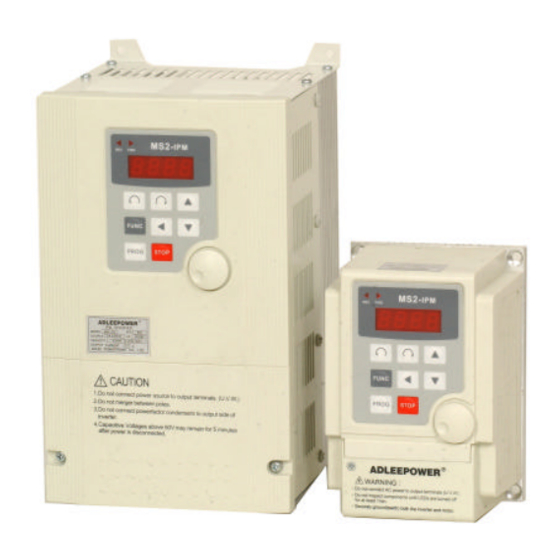
- Page 1 ADLEEPOWER INSTRUCTION MANUAL GENERAL-PURPOSE INVERTER MS2-102 ~ MS2-137 THANK YOU VERY MUCH FOR YOUR PURCHASE OF ADLEE INVERTER MS SERIES. PLEASE READ THIS INSTRUCTION MANUAL BEFORE INSTALLATION OF THE INVERTER.
- Page 2 PREFACE This general-purpose inverter made by ADLEE Powertronic., Ltd. Read this instruction manual throughly before operation. This manual will be helpful in the installation, parameter setting, troubleshooting, and daily maintenance of the AC motor drives. To guarantee safe operation of the equipment, read the following safety guidelines before connecting power to the AC drives.
- Page 3 RECEIVING CAUTION * Do not install or operate the driver which is damaged or has missing parts. Failure to observe this caution may result in personal injury or equipment damage. INSTALLATION CAUTION * Lift the cabinet by the base. When moving the unit, never lift by the front cover.
- Page 4 CAUTION * Verify that the driver rated voltage coincides with the AC power supply voltage. Failure to observe this caution can result in personal injury or a fire. * Do not perform a withstand voltage test of the driver. It may cause semi-conductor elements to be damaged. * To connect a braking resistor, follow in APPENDIX A.
-
Page 5: Maintenance And Inspection
CAUTION * Since it is easy to change. operation speed from low to high speed, verify the safe working range of the motor and machine before op- eration. Failure to observe this caution can result in personal injury and machine damage. * Do not change signals during operation. - Page 6 CAUTION * The control PC board employs CMOS ICs. Do not touch the CMOS elements by hand. They are easily damaged by static electricity. * Do not connect or disconnect wires or connectors while power is applied to the circuit. Failure to observe this caution can result in personal injury.
-
Page 7: Table Of Contents
CONTENTS 1. RECEIVING 2. SPECIFICATIONS 3. DIMENSION DRAWINGS 4. INSTALLATION 5. DESCRIPTION OF TERMINALS 6. DIGITAL OPERATION PANEL 7. FUNCTIONS DESCRIPTION 8. DISPLAY ERROR CODES 9. PRECAUTIONS 10. TROUBLESHOOTING 11. APPLICATION 12. INVERTER SELECTION 13. APPENDIX A. Optional braking resistor B. -
Page 8: Receiving
1. RECEIVING This MS series AC drive has gone through rigorous quality control tests at the factory before shipment. After receiving the AC drive, please check for the following : (1) No damage is found on each product after shipping. (2) The product is as ordered (check the nameplate, voltage and fre- quency). -
Page 9: Specifications
2. SPECIFICATIONS Model Voltage 1 110VAC 10% 220VAC ψ ± ψ ± Model No MS1-104 MS1-107 MS2-102 MS2-104 MS2-107 MS2-115 MS2-122 MS2-137 Input Frequency 50HZ ~ 60HZ ± Output Voltage 220VAC ψ Output Frequency 0.5 ~ 1200HZ Output 2.5 A 4.1 A... -
Page 10: Dimension Drawings
3. DIMENSION DRAWINGS Unit : mm Fig 1... - Page 11 Unit : mm Fig 2...
- Page 12 Unit : mm Fig 3...
-
Page 13: Installation
4. INSTALLATION Inadequate environment around installation site and installation surface can result in damage to the inverter. Before operating the MS series inverter, please check the following points : (1) Avoid high temperature, high humidity, easy-to-dew ambient envi- ronment. Don’ t expose to dust or dirt, corrosive gas, and coolant mist, and direct sunlight. -
Page 14: Description Of Terminals
5. DESCRIPTION OF TERMINALS (1) Main circuit connection diagram L1 L2 Ω GROUND External braking resistor POWER MOTOR Refer to the appendix A SOURCE Main circuit terminal Symbol Description Terminal name Ground Ground(Earth) Terminal (L1,L2) Single Phase 220VAC± 10% Connect power supply 110VAC±... - Page 15 (2) Control circuit terminal MA CF3 MC A/B C VCC FA1 GNDFWDREV FT1 FT2 MT COM Fault Relay Contact rating 1A 240VAC 1A 30VDC...
- Page 16 Running relay terminal Symbol Terminal name Description Running signal A Running contact (normal open) Running signal B / multi- Running contact (normal close) / 5-8th function terminal speed terminal Running signal C Running contact (common) Alarm terminal Symbol Terminal name Description Fault alarm contact A(normal open) / Alarm output B...
- Page 17 (3) Description of Hardware setting MS1-104~107, MS2-102~122 RS485 MS2-137 RS485...
- Page 18 3-1 Jumper setup 1. JP1 : VR on panel / VR on F306 VR on panel VR on F306 2. S1 : MB / CF3 selection 2 and 3 short CF3→ 1 and 2 short CF3 → Running relay MB 5-8th speed terminal (Refer Example 05) 3.
- Page 19 (4) WIRING 4-1 Wiring of main circuit THRY Filter 4-2 Wiring equipments Select the wiring equipment and wiring size, refer to the table below. 1. On the input power side, a molded case circuit breaker (MCCB) to protect inverter primary wiring should be installed. 2.
- Page 20 4-3 Surge absorber In order to prevent malfunction, provide the surge absorber on the coils of the electromagnetic contactors, relays and other devices which are to be used adjacent of the inverter. 4-4 Cable size and length If the inverter is connected to a distant motor (especially when low frequency is output), motor torque decreases because of voltage drop in the cable.
- Page 21 B. Control signal circuit 1. Separate the power cables of main circuit etc. from the control cables of the sequence and analog signals by passing the cables through the different ducts. 2. Use twisted pair shielded wire for control signal and connect the shield to earth terminal at on end, COMMON terminal of control board.
-
Page 22: Digital Operation Panel
6. DIGITAL OPERATION PANEL LED Operating MS2- Model Indication Indication Digital Indication FUNC CHARGE LED Operating Indication F306 PROG STOP Digital Indication REMOTE CONTROL FUNC STOP Operation key Key function Description FWD RUN Forward run Commands forward run REV RUN Reverse run Commands reverse run Cursor... -
Page 23: Functions Description
7. FUNCTIONS DESCRIPTION DISPLAY FUNCTION DEFAULT VALUE CODE 60.0HZ CD00 First speed setting ☆ 50.0HZ CD01 Parameter lock CD02 Acceleration time 1 10.0Sec CD03 Deceleration time 1 10.0Sec CD04 Jogging frequency 5.0HZ CD05 Start frequency 0.5HZ CD06 Jog mode 120.0 CD07 Analog output gain ☆... - Page 24 ADJUST USER UNIT REMARK RANGE SETTING 60HZ region 0.0 ~ 1200HZ 0.1HZ 50HZ region 0 or 1 0 = lock 1 = Unlock 0.1 ~ 6000.0Sec 0.1Sec 0.1 ~ 6000.0Sec 0.1Sec 0.0 ~ 1200HZ 0.1HZ 0.5 ~ 30.0HZ 0.1HZ 0 or 1 0 = Normal 1 = Jog 60HZ region 30.0 ~ 1200HZ...
- Page 25 DISPLAY FUNCTION DEFAULT VALUE CODE CD18 V/F pattern setting CD19 DC braking time 1.0Sec CD20 DC braking power CD21 Torque boost 0.0% CD22 Second speed setting 20.0HZ CD23 Third speed setting 30.0HZ CD24 Fourth speed setting 40.0HZ CD25 Acceleration time 2 10.0Sec CD26 Deceleration time 2...
- Page 26 ADJUST USER UNIT REMARK RANGE SETTING 0 : Constant torque 0 ~ 2 1 : (Frequency) 2.0 2 : (Frequency) 3.0 0.0 ~ 25.0Sec 0.1Sec 0 ~ 250 0.0 ~ 25.0% 0.1% 0.0 ~ 1200HZ 0.1HZ 0.0 ~ 1200HZ 0.1HZ 0.0 ~ 1200HZ 0.1HZ 0.1 ~ 6000.0Sec...
- Page 27 DISPLAY FUNCTION DEFAULT VALUE CODE CD38 Errors record 2 NONE CD39 Errors record 3 NONE CD40 Clear errors record CD41 HZ / RPM Display CD42 FT1 Multi-Function Terminal 1 CD43 FT2 Multi-Function Terminal 2 CD44 FA1 Free Analog Terminal 1 CD45 Reserved CD46...
- Page 28 ADJUST USER UNIT R E M A R K RANGE SETTING 0 or 1 1 = Clear 0 ~ 1 0 = HZ Display 1 = RPM Display 0 ~ 15 0 ~ 15 0 ~ 15 0.0 ~ 1200HZ 0.1HZ 0.0 ~ 1200HZ 0.1HZ...
- Page 29 DISPLAY FUNCTION DEFAULT VALUE CODE CD60 2st step timer 0.00 CD61 3st step timer 0.00 CD62 4st step timer 0.00 CD63 5st step timer 0.00 CD64 Timer unit selector CD65~ Reserved CD73 CD74 Address setting CD75 Transmission speed CD76 Transmission fault treatment CD77 Reserved CD78...
- Page 30 ADJUST USER UNIT REMARK RANGE SETTING 0 ~ 15Hr hr.min 0 ~ 15Hr hr.min 0 ~ 15Hr hr.min 0 ~ 15Hr hr.min 0 or 1 1 ~ 255 0 ~ 3 0 ~ 3 0 ~ 7...
- Page 31 Communication address description CODE FUNCTION DEFAULT VALUE Speed command for RS485 Frequency data output for RS485 Reserved Fault code for RS485...
- Page 32 ADJUST USER UNIT REMARK RANGE SETTING 0 ~4 0.1HZ...
- Page 33 7-1. Function setting Before starting test run, check carefully the following points : (1) Be sure to connect the power supply to L1, L2 (input terminals) and the motor to U.V.W. (output terminals). (Wrong connections will damage the inverter.) (2) Check that the input power supply coincide with input voltage and input phase of the inverter.
- Page 34 Operating 1-1. Pannel Action : (a) Press for forward / reverse operation. Speed : (a) Using to change motor speed with 1HZ increment step. or to select the digit for quick setting and confirm by PROG Standby : (a) Press back to standby mode after trip or function STOP setting mode.
- Page 35 Setting Range 0.0 ~ 1200HZ First speed setting 60HZ region 60.0HZ CD00 50HZ region 50.0HZ Press key for increase or decrease the speed. Press key to select the digit for quick setting. Press to save the setting value. PROG Parameter lock Setting Range 0 or 1 Default value...
- Page 36 Deceleration time 1 Setting Range 0.1 ~ 6000.0Sec Default value 10.0Sec CD03 CD03 value corresponds to the 60HZ time of deceleration from 50/60HZ to 0. 6000 TIME(Sec) Jogging frequency Setting Range 0.0 ~ 1200HZ Default value 5.0HZ CD04 1200HZ Use terminal control refer to CD12 and CD42 setting, keyboard control refer to CD06.
- Page 37 Jog mode Setting Range 0 or 1 Default value CD06 0 : Normal 1 : Jog Mode 1. Set jogging operation from key panel & LED blinking in JOG mode. Note : Refer to CD12 & CD42 for using jog mode by terminal control. Setting Range 30.0 ~ 1200HZ Frequency meter...
- Page 38 Analog / Digital Setting Range 0 or 1 frequency input Default value CD10 0 : Operation frequency change by using key and confirm by PROG 1 : Operation frequency depends on the analog of the knob. Note : Using key to change motor speed when CD01=1, the OPE3 warning message will be indicated.
- Page 39 Source operation command Setting Range 0 ~ 2 Default value CD13 0 : Normal 1 : F306 2 : RS485 communication Note : After finished this parameter setting, please repower “ON”. Maximum Setting Range 0.5 ~ 1200HZ frequency limit 60HZ region 120.0HZ CD14 50HZ region...
- Page 40 Frequency display Setting Range 0.1 ~ 500.0 scale 60HZ region CD16 50HZ region 30.0 Use the following equation to calculate the mechanical shaft speed in rpm. RPM = HZ Scale setting × When RPM > 9999 display for over range warning in this condition.
- Page 41 Constant power setting range 100% 25HZ 400HZ Constant torque V/F pattern setting Setting Range 0 ~ 2 Default value CD18 0 = Constant torque curve Volt 100% 1 = Reduce torque curve F 2 = Reduce torque curve F 1200(Hz) DC braking time Setting Range 0.0 ~ 25.0Sec...
- Page 42 DC braking power Setting Range 0 ~ 250 Default value CD20 (HZ) CD20 setting DC voltage gain various braking DC Voltage power. 25sec Torque boost Setting Range 0.0 ~ 25.0% Default value 0.0% CD21 Torque boosting is used to compensate the torque lost due to stator resistance.
- Page 43 Fourth speed setting Setting Range 0.0 ~ 1200HZ Default value 40.0HZ CD24 Terminal Operation Signal order CF1 CF2 Terminal CF1 Terminal CF2 SPEED SPEED - 1 OFF OFF Output frequency SPEED - 2 ON Speed 1 Speed 1 SPEED - 3 OFF ON Speed 2 Speed 4 Speed 3...
- Page 44 Carrier frequency Setting Range 1.0 ~ 16.0K Default value 16.0K CD27 Increase the carrier frequency would reduce motor noise but efficiency might be decreased. Reduce the carrier frequency would increase noise and reduce motor current, and gain better efficiency. current current Low carrier frequency High carrier frequency...
- Page 45 Frequency jump 2 Setting Range 0.0 ~ 1200HZ Default value 0.0HZ CD30 Frequency jump 3 Setting Range 0.0 ~ 1200HZ Default value 0.0HZ CD31 JUMP 1 JUMP 3 JUMP 2 Speed command Jump range Setting Range 0.5 ~ 3.0HZ Default value 0.5HZ CD32 Speed command...
- Page 46 Frequency Setting Range 0.0 ~ 1200HZ reference bias Default value CD33 Move Frequency bias with 100% same gradient. Frequency in the range of “-” bias, motor is stop. +Bias Analog input -Bias Freq. ref. bias direction Setting Range 0 or 1 Default value CD34 0 = Positive...
- Page 47 200% (HZ) 100% Vmax Analog input The latest error record CD36 Error record 1 CD37 Error record 2 CD38 Error record 3 CD39 Errors record flow-chart when Error occur. The new content will shift the other contents to one higher CD code and the highest one will be dropped.
- Page 48 Clear errors record Setting Range 0 or 1 Default value CD40 Set CD40=1 and clear CD36 ~ CD39 Error record the contents in PROG CD36 ~ CD39 are NONE “ “ HZ/RPM Display Setting Range 0 ~ 1 Default value CD41 0 = HZ Display 1 = RPM Display...
- Page 49 Note : 1. Set jumper J4 and J5 to appropriate location before using FT1/FT2 functions. 2. To operate at 8 speeds function, all FT1/FT2/CF3 terminals set as FT1=CF1, FT2=CF2 and CF3=CF3. 3 - WIRE CIRCUIT CONNECTION DIAGRAM (terminal latch function) FWD(REV) COMMAND CD42=5 STOP COMMAND...
- Page 50 Free analog terminal 1 Setting Range 0 ~ 15 Default value CD44 Setting Range Function Min-------Max ---------- ---------- Acceleration time 1 0 ~ CD02 Content Deceleration time 1 0 ~ CD03 Content Acceleration time 2 0 ~ CD25 Content Deceleration time 2 0 ~ CD26 Content Boost setting 0.0 ~ 25%...
- Page 51 SPEED CF3 CF2 CF1 5th speed setting 1th speed setting OFF OFF OFF CD47 2th speed setting OFF OFF ON 3th speed setting OFF ON 6th speed setting 4th speed setting OFF ON CD48 5th speed setting ON OFF OFF 6th speed setting ON OFF ON 7th speed setting 7th speed setting...
- Page 52 Setting Range F50.0 / F60.0 Version selector 60HZ region F60.0 CD52 50HZ region F50.0 Select function CD52, then use UP/Down key to select F50.0/F60.0 Version. Press to save it. System will return to the factory set- PROG ting and go into standby mode. S curve Setting Range 0 ~ 10...
- Page 53 4 ~ 20 mA speed command Setting Range 0 ~ 3 Default value CD54 Set FA1 for current signal (4 ~ 20mA). This function only effects in CD44=8,9,10,13 0 : NO current signal application 1 : Current signal in terminal FA1 Fmax 2~3 : Reserved Fmin...
- Page 54 2nd Maximum Setting Range 25.0 ~ 1200HZ Voltage frequency Default value 60.0HZ CD56 Set CD42(CD43)=7 define FT1(FT2) terminal for hardware V/F curve switcher. Open : select the 1st V/F curve preset in CD17 Close : select the 2nd V/F curve preset in CD56 100% 1 V/F 2 V/F...
- Page 55 CD58 Auto running mode Speed with timing control disable Sequence running then constant speed running Sequence running then stop and repeat from 1st step for cycling Sequence running then stop and repeat from 1st step in reversed direction for cycling Sequence running, and repeat for cycling Sequence running then perform reverse direction and repeat for cycling Sequence running then stop...
- Page 56 CD58=3 CD48 CD49 CD50 CD47 CD00 CD59 CD61 CD63 CD59 CD60 CD61 CD62 CD63 CD59 CD60 CD62 CD47 CD50 CD49 CD48 CD58=4 CD00 CD00 CD48 CD48 CD49 CD49 CD50 CD50 CD47 CD47 CD59 CD60 CD61 CD62 CD63 CD59 CD60 CD61 CD62 CD63 CD59...
- Page 57 1st step timer Setting Range 0 ~ 15 Hr Default value 0.01 Hr.min CD59 Setting running time for 1th speed.(CD47) 2st step timer Setting Range 0 ~ 15Hr Default value 0.00Hr.min CD60 Setting running time for 2th speed.(CD48) 3st step timer Setting Range 0 ~ 15Hr Default value...
- Page 58 Timer unit selector Setting Range 0 ~ 1 Default value CD64 0 : hr.min 1 : min.sec Note 1 : CD64 cannot be reset to default value by CD52. Set CD64 as needs separately. Note 2 : In RS485 communication input, CD59~CD63 need to tranfer minimum unit.
- Page 59 Transmission fault Setting Range 0 ~ 3 treatment Default Value CD76 0 : Alarm and keep operation. 1 : Alarm and decelerate to stop. 2 : Alarm and free to stop. 3 : No alarm and keep operation. Communicator Setting Range 0 ~ 7 protocol Default Value...
- Page 60 3 : 8,O,1 RTU (1 start bit+8data bits+1 Odd bit+1 stop bit) 8,O,1 RTU (11-bit)(character frame in hexadecimal) Start Stop Parity 4 : 8,N,1 ASCII (1 start bit+8data bits+1 stop bit) 8,N,1 ASCII (10-bit)(character frame in hexadecimal) Start Stop 0 1 2 3 4 5 6 7 5 : 8,N,2 ASCII (1 start bit+8data bits+2 stop bit) 8,N,2 ASCII (11-bit)(character frame in hexadecimal) Start...
- Page 61 B. Communication protocol Data contents are in hexadecimal with postive and negative format. 1. RTU Start A silent interval of more than 10ms Address 8-bit address Function 8-bit command Data (n-1) Contents of data : n*8-bit data, n 16 ≦ Data 0 CRC CHK Low Check sum (CRCL)
- Page 62 C. ASCII code description Character "0" "1" "2" "3" "4" "5" "6" "7" ASCII code 30H 31H 32H 33H 34H 35H 36H 37H Character "8" "9" "A" "B" "C" "D" "E" "F" ASCII code 38H 39H 41H 42H 43H 44H 45H 46H D.
- Page 63 Example : Read two parameters of AC drive address 52(34H) from CD22. CD22=20.00(07D0H) CD23=30.00(0BB8H). 1. RTU Computer command message AC drive response message D1 Address D1 Address D2 Function D2 Function Quantity of data D3 Start address (H) (count by byte) D4 Start address (L) D4 CD22 content (H) D5 # of data (H)
- Page 64 Computer command message AC drive response message # of data '0' CD23 content '0' # of data '2' CD23 content 'B' count by word '2' CD23 content 'B' CD23 content '8' D7 LRC HI LRC HI D8 LRC LO LRC LO D8 LRC HI LRC HI END HI...
- Page 65 Note 3 : Processing decimal number Using following methods to process if the minimum parameter value is decimal number. Minimum unit by 1 decimal number : The original value times 10 to be a new number. Minimum unit by 2 decimal number : The original value times 100 to be a new number.
- Page 66 Computer write CD00 content (60.00HZ) to inverter address=52 1. RTU Computer command message CRCL CRCH AC drive response message CRCL CRCH 2. ASCII Computer command message AC drive response message Address '3' Address '3' Address '4' Address '4' Function '0' Function '0' Function '6' Function '6'...
- Page 67 Computer command message inverter address=52 foward run at 60.00HZ 1. RTU Step 1. Write CD00=60.00HZ (6000=1770H) to AC drive address=52 Computer command message CRCL CRCH AC drive response message CRCL CRCH Step 2. Write address 100 (64H)=1 Computer command message CRCL CRCH AC drive response message...
- Page 68 Computer command message AC drive response message Number of parameter '0' Number of parameter '0' Number of parameter '0' Number of parameter '0' Number of parameter '0' Number of parameter '0' Number of parameter '0' Number of parameter '0' CD79 content '1' CD79 content '1' CD79 content '7' CD79 content '7'...
- Page 69 Computer command message AC drive response message CD31 content '0' CD31 content '0' CD31 content '1' CD31 content '1' D7 LRC HI LRC HI D7 LRC HI LRC HI D8 LRC LO LRC LO D8 LRC LO LRC LO END HI END HI END LO END LO...
- Page 70 Ex. Write data data 1=11, data 2=22, data 3=33 and data 4=44 to AC drive address 52(34H) 1. RTU Computer command message AC drive response message D1 Address D1 Address D2 Function D2 Function D3 Data 1 D3 Data 1 D4 Data 2 D4 Data 2 D5 Data 3...
- Page 71 Computer command message AC drive response message D7 LRC HI LRC HI D7 LRC HI LRC HI D8 LRC LO LRC LO D8 LRC LO LRC LO END HI END HI END LO END LO CRC(Cyclical Redundancy Check) is calculated by the following steps: Step 1.
- Page 72 E. Communication error respond Once communication error happened, inverter will respond “Function code and 80H” and communication error code to master system. Communication error code definition Error code Description Function code error, only 03/06/08 available Illegal data value (data value outside limit value) Illegal data address (data address is not available) Illegal operation command Check sum error...
- Page 73 2. ASCII Start code Address (01) Function code & 80H (86) Error code (02) LRC (77) End code H End code L Ex. Write CD00=1500HZ(3A98H), but maximum value of CD00 is 1200HZ. 1. RTU Computer command message CRCL CRCH AC drive response message CRCL(C3H) CRCH(A1H)
- Page 74 2. ASCII Computer command message AC drive response message Address '0' Address '0' Address '1' Address '1' Function '0' Function '8' Function '6' Function '6' Address content '0' Error code '0' Address content '0' Error code '2' Address content '0' LRC HI '7' Address content '0' LRC LO '7'...
- Page 75 Communication address description Speed command of RS485 Setting Range 0 ~ 4 Default Value 0 : Normal 1 : Forward run 2 : Reverse run 3 : Stop 4 : Fail mode reset Note : 1.Fail mode reset by writting address 100 content=4. It will fall into EEP1 error mode if any operation command is set before reset the fail mode.
- Page 76 Fault code for RS485 Using 03H function to read address 103(67H) content to know the cause of fault if fault occurred. 01H : EP0 02H : PF01 03H : PF02 04H : PF03 05H : PF04 07H : OH 08H : OL 09H : EEP1 0AH : EEP2 31H : OPE1...
- Page 77 7-2. Operation key-in sequence EXAMPLE : CHANGE acceleration time Setting Display Description sequence indicator In waiting mode, the display is blinking Enter function mode FUNC Select function number 1 (parameter lock) Press "FUNC" again to change the parameter value FUNC Enable to change parameter Press "PROG"...
- Page 78 CHANGE maximum frequency limit Setting Display Description sequence indicator Enter function mode FUNC Increase the value to 4 Select the second digit Increase the value to 1 Press "FUNC" again to change the Maximum FUNC frequency limit Select the second digit Decrease the value to 90HZ Press "PROG"...
-
Page 79: Display Error Codes
8. DISPLAY ERROR CODES A. Inverter self-checking errors Internal protection Noise protection. Self test failure protection Program check sum error EEPROM access error EEP1 EEPROM check-sum error EEP2 Power device failure 1 PF01 Power device failure during acceleration Power device failure 2 PF02 Power device failure during constant frequency... - Page 80 Power device failure 3 PF03 Power device failure during deceleration (stopping) Power device failure 4 PF04 Power device failure during stand-by B. Operation errors Parameter Locked OPE1 To change the contents of CD02~CD52 set CD01=press first PROG FWD or REV only OPE2 Motor direction limiter.
- Page 81 Terminal command only OPE4 Accept run command from control terminalonly. Not operation panel. See function description CD12 Over range error OPE5 Operating error message ~ over range. Logic error warning OPE6 Logic error when setting. EXAMPLE : Setting F-min > F-max will result an error. Only changed in standby OPE7 The parameter can only be changed in standby mode.
- Page 82 Communication error OPE9 Over heat Over temperature for external indicator. Refer to CD42(FT1) or CD43(FT2). Over load...
-
Page 83: Precautions
9. PRECAUTIONS 9-1 Prior to maintenance, check the following : (1) Before maintenance, be sure to turn the power off and wait until the LED digits vanish in the display. However, approx. 50 VDC still remains immediately after the display disappears, so wait a little bit longer. -
Page 84: Troubleshooting
10. TROUBLESHOOTING Cause of fault message Display symbol Check point Suggested remedy contents Review the power system. Discharge LED Turned on or Replace No display Check that MCCB has been extinguished MCCB turned on or no poor contact. Increase the acceleration The acceleration time is too short. -
Page 85: Application
11. APPLICATION EXAMPLE 01 : Use 2 external variable resistor for multistage speed command input DESCRIPTION : CD10 = 1 ( Use frequency knob for 1st speed setting) CD12 = 1 ( External command) CD44 = 8 ( 2nd speed signal enter from FA1) SW1 = RUN / STOP SW2 = 1st / 2nd SPEED 1ST SPEED... - Page 86 EXAMPLE 02 : Normal / Jog operation DESCRIPTION : CD00 = Normal speed ; User setting CD04 = Jog speed ; User setting CD12 = 1 ; Terminal command (For External) CD42 = 1 ; Define FT1 Terminal = JOGF function CD43 = 2 ;...
- Page 87 EXAMPLE 03 : Using rheostart for 2stage speed setting DESCRIPTION : CD12 = 1 ; Terminal command (For External) CD44 = 8 ; 2nd speed singnal enter from FA1 Set FT1 jumper at CF1, see 3-1 description. TERMINAL SPEED SPEED COMMAND ENTRY FREQUENCY KNOB SPEED2(VR) ON/OFF...
-
Page 88: Function Setting
EXAMPLE 04 : Auto multi-speed and time programing DESCRIPTION : Speed :CD47=80 (High speed) Speed:CD48=12 (Low speed) Time:CD59=1.25 Time:CD60=0.18 5th SPEED (80HZ) 6th SPEED (12HZ) START STOP 1Hr 25min 18min CD58 Auto running mode Speed with timing control disable Sequence running then constant speed running Sequence running then stop and repeat from 1st step for cycling Sequence running then stop and repeat from 1st step in reversed direction for cycling... - Page 89 EXAMPLE 05 : 8th speed from terminal control DESCRIPTION : CD12=1 CD42=6 CD58=0 CD00 : 1st speed CD22 : 2nd speed CD23 : 3rd speed CD24 : 4th speed CD47 : 5th speed CD48 : 6th speed CD49 : 7th speed CD50 : 8th speed Jumper S1 Jumper J4...
-
Page 90: Inverter Selection
12. Inverter Selection Inverter Capacity Check Method Related factor Description Friction load and weight load Liquid(viscous) load Load type inerita load Load with power transmission and accumulation Load speed Constant torque and torque Constant power Load charcteristics Descreasing torque characteristics Motoring Braking or overhanging load Constant load... - Page 91 Speed and Overload Torque Time Ratings Starting torque Capacity Characteristics ※ ※ ※ ※ ※ ※ ※ ※ ※ ※ ※ ※ ※ ※ ※ ※ ※ ※...
-
Page 92: Appendix
13. APPENDIX A. Option braking resistor Part no : E-MSAA-008000 Ω Specification : 60 Remove build-in dynamic brake resistor. Connect a larger capacity resistor, the value should be greater than the table below : Unit : Ohm Model... -
Page 93: B. Terminal Wiring Diagram
B. Terminals wiring diagram External braking /80W MCCB SINGLE PHASE 110VAC±10% 220VAC±10% Motor 50/60HZ Ground Rheostat Forward run/stop Reverse run/stop Fault contact output Multi function 1 1A 240VAC 1A 30VDC Multi function 2 Normal close(B) contact 10 VDC (i.e 1mA) Running Relay contact (common) Running Relay normal close(B) contact (or 5-8th speed terminal) -
Page 94: C. Remote Operator
C. Remote operator UNIT : M/M A-0000-F306G3 F306 Remote operator E-WIAA-G5R001 1 meter extension cable E-WIAA-G5R003 3 meter extension cable E-WIAA-G5R005 5 meter extension cable... - Page 95 MEMO...
- Page 96 MEMO...
- Page 97 MEMO...
- Page 98 MEMO...
- Page 99 MEMO...
- Page 100 MEMO...
- Page 101 INSTRUCTION MANUAL PART NO : E-PHAA-EMSA02 Model : MS series DEC. 2007 1 edition ADLEEPOWER SERVICE OFFICE FREQUNCY INVERTER MOTOR DRIVES Guang Dong (China) Taiwan Tel No : 86-757-26656498 Tel No : 886-4-25622651 Fax No : 86-757-26658515 Fax No : 886-4-25628289 E-mail : webmaster@adlee.com Wu Han (China) Tel No : 86-27-59322991...
Need help?
Do you have a question about the MS2-102 and is the answer not in the manual?
Questions and answers