Table of Contents
Advertisement
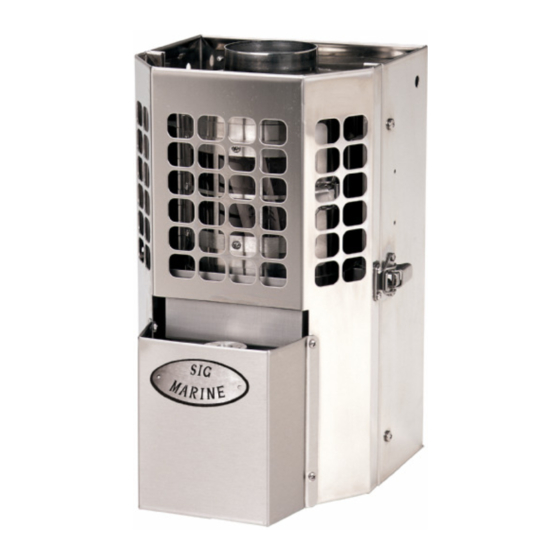
Natural Draft Diesel Heater
Operating and Installation
Instruction Manual
*KEEP THIS MANUAL FOR FUTURE REFERENCE*
Sig100, 120, 170, 180
** Please read from beginning to end before installing and operating.
Heater's Serial #: __________________
Quality Controlled by- Doug & Don
Form#7.2-256 Issue#2 Sept 5th, 2012
Advertisement
Table of Contents

Subscribe to Our Youtube Channel
Related Manuals for Sig Marine Sig100


Summary of Contents for Sig Marine Sig100
- Page 1 Natural Draft Diesel Heater Operating and Installation Instruction Manual *KEEP THIS MANUAL FOR FUTURE REFERENCE* Sig100, 120, 170, 180 ** Please read from beginning to end before installing and operating. Heater’s Serial #: __________________ Quality Controlled by- Doug & Don...
-
Page 2: About A Natural Draft Diesel Heater
3. Fuel- Input in proportion to the supply of draft and oxygen. Sig Marine diesel heaters can also be calibrated to run kerosene (K) and stove oil (S). See “Fuel Variations” on Pg. 23. This code will be indicated on the side of the valve. -
Page 3: Important Notes
Hot water coils are also available in 2 turn coils to heat approx. 15-20 gallons of water. 2. Important Notes Here are some important notes to remember when installing a Sig Marine diesel heater: • Mounting & location, 12v power hook-up, minimum 4ft and a maximum 10ft of chimney, the location of hole for the chimney &... -
Page 4: How Does The Chimney Affect The Heater
It is important to create and maintain a positive pressure inside the boat. High winds can draw air out from the boat and thus create a negative pressure. This condition can result in down drafts. Ensure that when you do have windows open that they do not create a suction effect in the cabin due to the window’s position and the wind direction. - Page 5 the volume of air entering the boat, and the boat will gradually become depressurized. With lower pressure in the boat than outside, there will be a tendency for air to be drawn back into the boat from all available openings including down the chimney. 2.
-
Page 6: Installing Your Heater
5. Installing your Heater Location Plan your heaters location prior to installing to ensure the location chosen will fit the specifications and safety clearances. Combustible material closer to the heater then the specified safety clearances must be lined with insulation or millboard and a metal liner with a .5” standoff for air movement behind. - Page 7 Mounting The Sig heaters have the appropriate brackets to secure the heater to the bulkhead. The drip tray will then fit under the bottom of the heater. **REMEMEBER: remove all protective plastic on ALL parts of the heater. Chimney Pipe The location and configuration of the chimney stack is very important to the operation of the heater.
- Page 8 Install the barometric tee pipe with the front flap facing fore and aft. In order for the barometric to work efficiently it must be installed between 12” and 24” from the top of the heater. If using a flue guard, turn the barometric tee to the back as it does not have to be seen to work To adjust the flap on the barometric, back off the jam nut and turn the counterweight so the flap is standing closed.
- Page 9 Deck Fitting To install the thru deck fitting, a hole must be cut in your deck. Depending on the diameter of the chimney stack will depend on the size hole that needs to be cut. There should be a 1” clearance all around the chimney pipe. For example, a 3”...
-
Page 10: Heater Installation Diagram
Heater Installation Diagram... -
Page 11: Fuel System Installation
6. Fuel System Installation For efficient and safe operation of the heater, follow all recommendations for properly installing the fuel system. DANGER: Never use gasoline in a heater. Use only #2 diesel, #1 stove oil or kerosene. The valves are factory calibrated to #2 diesel; if #1stove oil or kerosene is preferred, the valves can be re-calibrated to suit those viscosities. - Page 12 you will need to burn off the fuel in the line before re-opening the shut-off valve. Do not use a check valve. Remember to re-open the shut-off valve on the overflow line. Fuel Filter & Manual Shut-off’s The fuel must be filtered before the fuel pump and before the oil metering valve to prevent dirt and debris from plugging up the check valves in the pump and the needle and seat in the valve.
- Page 13 7. Walbro Fuel Pump Installation When installing a Walbro fuel pump you must ensure it is mounted approximately at the level of the valve on the heater. These pumps can “pull” fuel but have trouble “pushing” fuel so it must be gravity fed from the pump to the heater.
- Page 14 Marine to order a stronger spring & regulator. info@sigmarine.com Once you have received a stronger spring and regulator from Sig Marine, you can upgrade your pump to a stronger pressure. Unscrew the 3 torx screws (t-20) and with twisting the lid back and forth, pull it straight back off.
- Page 15 opposite end of the spring. Replace the lid with the gasket on by lowering your finger on to the red O ring sleeve without the plunger falling out (the plunger is about 2” long so you have room to lower your finger out of the way).
-
Page 16: Draft Assist Fan Installation
8. Draft Assist Fan Installation The 12v draft assist is not needed for operation but highly recommended as it will help to vaporize the fuel and give more control in burning the heater as clean as possible. The fan is a 12v DC fan that the draw is .17amp. The fan is 12v and if 24v or 32v is needed, resistors are available. -
Page 17: Operation
9. Operation The first time the oil-metering valve is turned on it will take 5-10 minutes for the fuel lines to fill and oil to appear in the bottom of the burner. Lighting Procedure 1. Turn on the fuel pump or open the gravity feed valve to allow fuel to flow into the oil metering valve on the heater. -
Page 18: Approximate Valve & Fan Settings
11. Approximate Valve & Fan Settings Heater Temperature Fan Knob Position Cold Start Warm Low Warm Low (cold or windy) 4 to 5 o’clock Medium 5 to 6 o’clock Medium (cold or windy) 6 to 7 o’clock High 7 o’clock * Operating the fan can deliver too much air and cause the burner to run too lean (too much air in the fuel to air mixture). -
Page 19: Operation Tips
12. Operation Tips When operating on the lower temperature settings the burner needs less air. To reduce the air, adjust the barometric damper open wider, turn off the fan, and add more fuel even if you do not want the heat. It is better to make too much heat and dissipate it than to run the burner too lean with flames inside the burner pot as this will result in hard carbon build up and soot. -
Page 21: Flooding The Burner
13. Flooding the Burner A vaporizing oil burner of this type can be flooded if care is not taken to prevent excess oil entering the burner when lighting. By following the lighting instructions flooding will be avoided. A flooded burner that is still burning should be turned off and the heater monitored until the oil has burned off. -
Page 22: The Oil Metering Valve & Fuel Flow
14. The Oil Metering Valve & Fuel Flow Safety Fuse A high temperature fuse is incorporated into the oil metering valve. The adjusting screw on the top of the knob of the oil metering valve is fitted with a fusible sleeve. This fuse will melt if the valve knob reaches a temperature of 165 degrees F. - Page 23 Fuel Flow Measurements If your heater is burning rich (making soot or smoking) or burning lean (flames not burning above the top burner ring), adjust the valve fuel flow as follows regardless of what type of fuel: Unscrew the compression nut from the bottom of the valve with 2 wrenches and bend away the copper fuel line.
- Page 24 Oil Metering Valve Repair Kit Part# 905005 *For valves made from 2007-Present All Valves made prior to 2007 are discontinued and no parts are available. 1. Float (black) 2. High Temp Fuse c/w metering set & adjustment screw 3. Replacement fuel screen 4.
- Page 25 Place the new copper/brass washer in, then screw in the new seat into • the bottom casting until tight but not so tight as to damage the aluminum threads of the casting (35 inch pounds). • Place the new needle in the groove of the float and insert the float pin through the bracket and float, then snug up the float screw.
- Page 26 Oil Metering Valve Diagram...
-
Page 27: Burner Assembly
15. Burner Assembly Your diesel heater has been equipped with a Airflow burner. There are two components in the burner that must be correctly placed for the heater to operate properly. The burner ring must be placed at the top of the pot so the outside edge of the ring fits into the groove in the top of the pot. -
Page 28: Maintenance
16. Maintenance Fuel Maintenance Checklist (CHECK ONCE A YEAR) 1) Disconnect the fuel inlet line from the valve and place into a bucket. Turn on your pump or open your gravity feed valve to ensure there is a constant flow of fuel. This will indicate your fuel filter and fuel pump are operating correctly. -
Page 29: Troubleshooting
4) Using a paperclip, poke out the four rows of twelve air intake holes on the sides of the burner to ensure they are clear of any soot. 5) Remove any loose carbon from the base of the burner. 6) Remove the reamer tool and replace burner ring and the superheater. Cleaning the Fuel Line Any blockage in the fuel line from the oil-metering valve to the burner can be cleaned by removing the clean-out plug situated directly under the burner. - Page 30 *Flames are orange and dirty creating soot on the window & deck- The flames are burning too rich, this to say too much fuel and / or not enough air. Add air first by turning the fan on. Just add enough air to turn the flames vibrant yellow and not lazy orange with black tips, however adding too much air will burn off the fuel and the flames will end up below the top burner ring.
-
Page 31: Warranty Policy
Warranty Sig Marine warranties all of its products for a period of one year dated from the purchase of the product by the end user with proof of purchase or a registered warranty. We warrant our barbeque burners for a period of 3 years dated from the purchase of the product by the end user with a registered warranty. - Page 32 Sig Marine offers to replace said parts free of charge, provided, however, that such parts have not been improperly repaired, altered or tampered with or subjected to misuse, abuse or exposed to corrosive conditions.
- Page 33 CLAIM PROCEDURE: In the event of a defect, problem or that a breach of this warranty is discovered, in order to protect any warranty rights you must promptly notify Sig Marine. Give name, address, and model name, location of unit, description of problem and where you can be reached during business hours.
- Page 34 Do not use any substitutes of the heaters valve, burner or fan other then the ones supplied by Sig Marine. Sig Marine accepts no liability for any damage or loss of service resulting from unapproved modifications.
- Page 35 All rights reserved. No part of this manual may be reproduced without permission in writing from Sig Marine. Sig Marine also reserves the right to modify or change without notice, any materials, applications, equipment, accessories, and/or prices. All measurements and weights are approximate.
Need help?
Do you have a question about the Sig100 and is the answer not in the manual?
Questions and answers