Table of Contents
Advertisement
Available languages
Available languages
Quick Links
Advertisement
Table of Contents

Related Manuals for Architectural Acoustics AUTOMIX CONTROL 8

Summary of Contents for Architectural Acoustics AUTOMIX CONTROL 8
- Page 1 AUTOMIX CONTROL 8 User Manual ™ 8 Channel Auto Mixer...
- Page 2 Intended to alert the user to the presence of uninsulated “dangerous voltage” within the product’s enclosure that may be of sufficient magnitude to constitute a risk of electric shock to persons. Intended to alert the user of the presence of important operating and maintenance (servicing) instructions in the literature accompanying the product.
-
Page 3: Important Safety Instructions
IMPORTANT SAFETY INSTRUCTIONS WARNING: When using electrical products, basic cautions should always be followed, including the following: Read these instructions. Keep these instructions. Heed all warnings. Follow all instructions. Do not use this apparatus near water. Clean only with a dry cloth. Do not block any of the ventilation openings. -
Page 4: Wichtige Sicherheitshinweise
WICHTIGE SICHERHEITSHINWEISE ACHTUNG: Beim Einsatz von Elektrogeräten müssen u.a. grundlegende Vorsichtsmaßnahmen befolgt werden: Lesen Sie sich diese Anweisungen durch. Bewahren Sie diese Anweisungen auf. Beachten Sie alle Warnungen. Befolgen Sie alle Anweisungen. Setzen Sie dieses Gerät nicht in der Nähe von Wasser ein. Reinigen Sie es nur mit einem trockenen Tuch. -
Page 5: Instructions Importantes De Securite
INSTRUCTIONS IMPORTANTES DE SECURITE ATTENTION: L’utilisation de tout appareil électrique doit être soumise aux precautions d’usage incluant: Lire ces instructions. Gardez ce manuel pour de futures références. Prétez attention aux messages de précautions de ce manuel. Suivez ces instructions. N’utilisez pas cette unité proche de plans d’eau. N’utilisez qu’un tissu sec pour le nettoyage de votre unité. - Page 6 INSTRUCCIONES IMPORTANTES PARA SU SEGURIDAD CUIDADO: Cuando use productos electrónicos, debe tomar precauciones básicas, incluyendo las siguientes: Lea estas instrucciones. Guarde estas instrucciones. Haga caso de todos los consejos. Siga todas las instrucciones. No usar este aparato cerca del agua. Limpiar solamente con una tela seca.
-
Page 7: Theory Of Operation
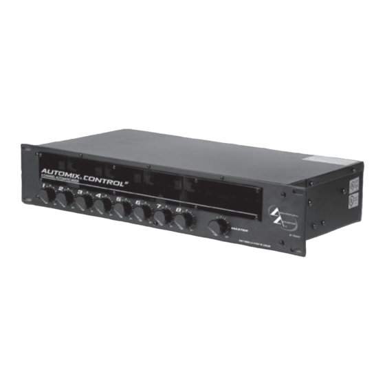
ENGLISH AUTOMIX™ CONTROL 8 8 Channel Automatic Mixer Thank you for purchasing the Automix Control 8! The Architectural Acoustics Automix Control 8 is a Introduction high quality automatic mixer with eight transformer balanced mic/line inputs. Each channel provides a gain control, 48 volt phantom power (mic inputs), low cut filter, activity/clipping LED, an Aux send control and a choice between manual or automatic operation. -
Page 8: Channel Level
Front Panel 1. CHANNEL LEVEL Manual Mode: In the manual mode the channel level controls provide 6 dB of gain and 50 dB of attenuation. Auto Mode: In the auto mode the control still provides 50 dB of attenuation, but the control does not add gain to the overall system level. - Page 9 4. AUX SEND CONTROL Internal Panel Controls the level of the signal being sent to the AUX bus. The level being sent to the Aux bus will also be affected if the gain control in that channel is changed. 5. GAIN TRIM This control sets the input gain in each channel.
-
Page 10: Power Led
12. NOTCH FILTER FREQUENCY CONTROL Internal Panel The notch filter frequency control is used to select the center frequency of the notch filter. The bottom filter has a range of 40 Hz to 925 Hz. The middle filter has a range of 260 Hz to 6 kHz. -
Page 11: Direct Outputs
Rear Panel 17. DIRECT OUTPUTS Each channel has direct output terminals that can be used for recording or anytime the output of an individual channel is required. This signal is independent of “Automix” gain manipulation. The nominal output level is 2.21 dBu (1 volt). MUTE Channels can be muted individually by shorting this terminal to ground. -
Page 12: Link Switch
Rear Panel 22. LINK PORT To increase the number of inputs available, multiple Automixers can be linked together. Linking automixers is a very simple process. It can be done with a small flat-head screwdriver and a short length of four conductor shielded wire. The following diagram and procedures will ensure proper linking. - Page 13 25. IEC INLET (AC) Rear Panel With the Power Switch in the off (O) position, plug the power cord into this connector prior to plugging into your AC power source. Always ensure proper AC voltage and grounding practices are utilized (proper voltage is labeled under inlet). NOTE: FOR UK ONLY As the colors of the wires in the mains lead of this apparatus may not correspond with the colored markings identifying the terminals in your plug, proceed as follows: (1) The wire...
-
Page 14: Input Specifications
AUTOMIX CONTROL 8 SPECIFICATIONS ™ Nominal Out = 2.21 dBu = 1 volt Input Specifications: Function Input z Input Gains Input Levels Bal./ Connector (ohms) Setting (to bal. outputs) Unbal. Min* Nominal** Microphone Max Gain -64 dBu -43 dBu -2 dBu Bal. -
Page 15: General Specs
AUTOMIX CONTROL 8 SPECIFICATIONS ™ Hum and Noise: Output Residual Noise S/N Ratio Test Conditions Ref: 0 dBu Ref: 2:21 dBu Main Out -85 dBu 87 dB All controls down -84 dBu 86 dB One channel nominal, Master level nominal -85 dBu 87 dB All controls down... -
Page 17: Initial Control Settings
AUTOMIX CONTROL 8 ™ Setting up the Automix Control 8 1. Wiring Inputs and Outputs: For best results, it is recommended that two-conductor shielded cable is used for all input and output connections. When making connections remember to observe proper polarity. The recommended strip length for the detachable screw terminals is 1/2". -
Page 18: Operación
1/9 de octava, un expansor descendente, salidas equilibradas por transformador (principal y auxiliar) y conexiones para control de volumen remoto. El mezclador Automix control 8 ha sido diseñado para interconectar fácilmente entre sí varias unidades y formar un único mezclador con muchas más salidas (16, 24, 32…). -
Page 19: Interruptores Dip
Panel Frontal 1. NIVEL DE CANAL Modo manual: En el modo manual, los controles de nivel de canal proveen 6 dB de ganancia y 50 dB de atenuación. Modo automático: En modo automático el control aún provee 50 dB de atenuación, pero no agrega ganancia al nivel general del sistema. - Page 20 4. CONTROL DE SEÑAL DE MUESTRA AUXILIAR Panel Interno Controla el nivel de la señal enviada al bus auxiliar. El nivel enviado al bus auxiliar también es afectado si se modifica el control de ganancia del canal. 5. LED ACTIVIDAD/RECORTE DE SEÑAL Este control configura la ganancia de entrada a cada canal.
-
Page 21: Entradas De Micrófono
12. CONTROL DE FRECUENCIA DE FILTRO DE MUESCA Panel Interno El control de frecuencia de filtro de muesca se utiliza para seleccionar la frecuencia central del filtro. El filtro inferior tiene una banda de 40 a 925 Hz; el filtro central tiene una banda de 260 Hz a 6 kHz;... -
Page 22: Salida Principal
17. SALIDAS DIRECTAS Panel Posterior Cada canal tiene terminales de salida directa que se pueden utilizar para grabación o cuando se necesite la salida de un canal individual. La señal es independiente de la ganancia del mezclador Automix™ Control 8. El nivel de salida nominal es 2,21 dBu (1 V). SILENCIADO DE SONIDO Los canales se pueden silenciar individualmente conectando este terminal a tierra. -
Page 23: Interruptor De Alimentación
Panel Posterior 22. PUERTO DE ENLACE Para aumentar la cantidad de entradas disponibles, se pueden interconectar entre sí varios mezcladores Automix, mediante un procedimiento muy sencillo. Sólo se requiere un destornillador de punta plana pequeño y un tramo corto de cable blindado de cuatro conductores. -
Page 24: Especificaciones De Salida
AUTOMIX CONTROL 8 ESPECIFICAIONES ™ Salida Nominal = 2.21 dBu = 1 voltio Especificaciones de la Entrada: Función Entrada z Entrada de Ganancias Entrada de Volumen Bal./ Conector (ohmios) Aplicaciones (para bal. salidas) Inbal. Min* Nominal** Micrófono Ganancia Max -64 dBu -43 dBu -2 dBu Bal. - Page 25 AUTOMIX CONTROL 8 ESPECIFICAIONES ™ Zumbido y Ruido: Salida Ruido Residual Radio S/N Condiciones de Test Ref: 0 dBu Ref: 2:21 dBu Salida Master -85 dBu 87 dB Bajando todos los controles -84 dBu 86 dB Un canal nominal, Nivel Master nominal -85 dBu 87 dB Todos los controles bajos...
- Page 27 AUTOMIX CONTROL 8 ™ Setting up the Automix Control 8 (Ajuste de la Automix) 1. Cableado de entradas y salidas: Para los mejores resultados, se recomienda usar cable blindado de dos conductores para todas las conexiones de las entradas y salidas. Recuerda observar la polaridad correcta al hacer las conexiones. El largo recomendado de la punta desnuda del cable para las conexiones terminales de tornillo es de 1.27 cm.
- Page 28 (main et aux) et des connexions pour le contrôle de volume à distance. L’Automix control 8 a été conçu pour être relié à d’autres unités afin de constituer un mixeur possédant un plus grand nombre d’entrées (16, 24, 32...). Il est par ailleurs équipé...
-
Page 29: Dip Switches
1. NIVEAU DU CANAL PANNEAU AVANT Mode Manuel: Dans ce mode, les contrôles de niveau permettent un contrôle de gain de +6 dB à -50 dB. Mode Automatique: En mode Automatique, le contrôle fournit toujours jusqu’à 50 dB d’atténuation mais n’augmentera pas le gain du canal. Cependant, lorsqu’il est réglé au dessus de “0”, le gain des autres canaux est atténué... - Page 30 4. CONTRÔLE AUX SEND PANNEAU INTERNE Détermine le niveau du signal envoyé au bus AUX. Ce niveau sera par ailleurs affecté par le contrôle de gain du canal correspondant. 5. GAIN Détermine le gain d’entrée. La plage de réglage s’étend de +25dB à +60dB (entrée Micro). 6.
- Page 31 12. FRÉQUENCE DU NOTCH FILTER PANNEAU INTERNE Ce contrôle permet de déterminer la fréquence centrale du notch filter. La fréquence de centrage du filtre Graves peut varier de 40Hz à 925Hz, celle du filtre Médiums de 260Hz à 6kHz et celle du filtre Aigus de 500Hz à 12kHz. 13.
- Page 32 17. SORTIES DIRECT PANNEAU ARRIÈRE Chaque canal possède une sortie direct pour l’enregistrement ou lorsque il est nécessaire de récupérer le signal d’un canal individuel. Ce signal est indépendant des manipulation de gain automatiques. Son niveau de sortie nominal est de 2.21dBu (1 Volt). MUTE Les canaux peuvent être mis en sourdine individuellement en mettant cette borne à...
-
Page 33: Interrupteur D'alimentation
PANNEAU ARRIÈRE 22. PORT LINK Pour augmenter le nombre d’entrées, plusieurs Automix peuvent être reliés ensembles. Pour cela, vous avez besoin d’un simple tourne-vis et d’une petite longueur de câble 4 conducteurs blindé. Suivez unes à unes les étapes ci-dessous: 1. - Page 34 AUTOMIX CONTROL 8 SPECIFICATIONS ™ Sortie Nominale = 2.21 dBu = 1 volt Specifications d’entrée: Fonction Entree z Entrée Gains Niveaux entrees Bal./ Connecteurr (ohms) Setting (to bal. sorties) Unbal. Min* Nominal** Microphone Gain Max -64 dBu -43 dBu -2 dBu Bal.
-
Page 35: Specifications Generales
AUTOMIX CONTROL 8 SPECIFICATIONS ™ Bruit et ronflement: Sorties Bruit Résiduel Ratio signal/Bruit Conditions de test Ref: 0 dBu Ref: 2:21 dBu Main Out -85 dBu 87 dB Tous les contrôles baissés -84 dBu 86 dB Un canal nominal, Niveau master(principal) nominal -85 dBu 87 dB... - Page 37 AUTOMIX CONTROL 8 ™ Installation de l’Automix Control 8 1. Câblage des entrées et des sorties: Pour obtenir des résultats optimaux, il est conseillé d’utiliser des câbles blindés à deux conducteurs pour toutes les connexions d’entrée et de sortie. Lorsque vous effectuez des branchements, n’oubliez pas de respecter les polarités.
-
Page 38: Funktionsweise
DEUTSCH AUTOMIX™ CONTROL 8 Automatisches 8-Kanal-Mischpult Wir möchten uns bei Ihnen dafür bedanken, dass Sie sich für den Automix Control 8 entschieden Einleitung haben! Der Automix Control 8 von Architectural Acoustics ist ein hochwertiges automatisches Mischpult mit acht trafosymmetrierten Mic-/Line-Eingängen. Jeder Kanal ist mit Gain-Regelung, 48-Volt-Phantomspeisung (Mikroeingänge), Tiefpassfilter, Betriebs-/Clipping-LED, Aux-Send-Regler... - Page 39 1. KANALPEGEL Front Panel Manual Mode: In diesem Modus bieten die Kanal Pegelregler 6 dB Gain und 50 dB Dämpfung. Auto Mode: In diesem Modus bietet der Regler immerhin noch eine Dämpfung von 50 dB, jedoch keine Verstärkung für den Haupsystempegel. Stattdessen werden die anderen Kanäle, sobald der Pegel über „0“...
- Page 40 4. AUX SEND REGLER Internal Panel Regelt den an den AUX Bus übermittelten Signalpegel. Dieser wird auch beeinflußt, wenn der Gain Regler im Kanal geändert wird. 5. GAIN TRIM Dieser Regler legt die Eingangsverstärung (Input Gain) in jedem Kanal fest. Die Gain Größe läßt sich von +25 dB bis +60 dB variieren.
-
Page 41: Line Eingänge
12. NOTCH FILTER FREQUENZREGLER Internal Panel Dieser wird zur Selektierung der Mittenfrequenz des Notch Filter benutzt. Der untere Filterbereich reicht von 40 Hz bis 925 Hz. Der mittlere Filterbereich reicht von 260 Hz bis 6 kHz. Der obere Filterbereich reicht von 500 Hz bis 12 kHz. 13. - Page 42 17. DIREKTAUSGÄNGE GERÄTERÜCKSEITE Jeder Kanal verfügt über direkte Output Terminals, die für Aufzeichnungen benutzt werden können oder jederzeit wenn der Ausgang eines individuellen Kanals erforderlich ist. Dieses Signal ist von der „Automix“ Gain Manipulation unabhängig. Der nominale Ausgangspegel beträgt 2.21dBu (1 Volt). MUTE Kanäle lassen sich individuell stummschalten, indem dieses Terminal mit Masse kurzgeschlossen wird.
- Page 43 GERÄTERÜCKSEITE 22. LINK PORT Um die Anzahl verfügbarer Eingänge zu erhöhen, lassen sich mehrere Automixer miteinander vebinden. Die nötige Vorgehensweise ist denkbar einfach. Dazu benötigen Sie einen Schraubendreher und ein abgeschirmtes 4-Leiter Kabel. Folgende Abbildung und Vorgehensweise versichern einen ordnungsgemäßen Link. 1.
- Page 44 AUTOMIX CONTROL 8 - TECHNISCHE DATEN ™ Nennleistung = 2,21 dBu = 1 Volt Technische Daten - Eingang: Funktion Eingangsimpedanz Eingangs-Gain Eingangspegel Sym./ Stecker (ohms) Einstellung (an sym. Ausgänge) Unsym. Min* Nenneinst** Mikrofon Max Gain -64 dBu -43 dBu -2 dBu Sym.
-
Page 45: Allgemeine Technische Daten
AUTOMIX CONTROL 8 - TECHNISCHE DATEN ™ Brummen und Rauschen: Ausgang Restrauschen Rauschabstand Testbedingungen Ref.: 0 dBu Ref.: 2,21 dBu Main Out -85 dBu 87 dB Alle Regler heruntergedreht -84 dBu 86 dB Ein Kanal Nennwert, Master-Pegel Nennwert -85 dBu 87 dB Alle Regler heruntergedreht Aux Out... - Page 46 AUTOMIX CONTROL 8 ™ Einrichten des Automix Control 8 1. Verdrahtung von Eingängen und Ausgängen: Um die besten Ergebnisse zu erzielen, wird empfohlen, für alle Eingangs- und Ausgangsanschlüsse zweiadriges geschirmtes Kabel zu verwenden. Beim Anschließen muss die korrekte Polarität beachtet werden. Die empfohlene Leistenlänge für die abnehmbaren Schraubklemmen beträgt 1,27 cm (0,5").
- Page 47 WARRANTY Architectural Acoustics ® PEAVEY ELECTRONICS CORPORATION LIMITED WARRANTY Effective Date: July 1, 1998 What This Warranty Covers Your Peavey Warranty covers defects in material and workmanship in Peavey products purchased and serviced in the U.S.A. and Canada. What This Warranty Does Not Cover The Warranty does not cover: (1) damage caused by accident, misuse, abuse, improper installation or operation, rental, product modification or neglect;...
- Page 48 Features and specifications subject to change without notice. Peavey Electronics Corporation 5022 Hartley Peavey Drive • Meridian • MS • 39305 Logo referenced in Directive 2002/96/EC Annex IV (601) 483-5376 • FAX (601) 486-1678 • www.peavey.com (OJ(L)37/38,13.02.03 and defined in EN 50419: 2005 The bar is the symbol for marking of new waste and is applied only to equipment manufactured after ©2005...
Need help?
Do you have a question about the AUTOMIX CONTROL 8 and is the answer not in the manual?
Questions and answers