Table of Contents
Advertisement
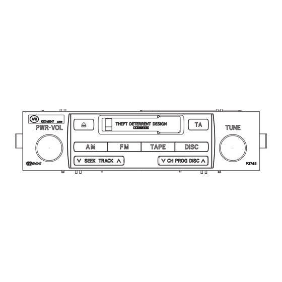
RECEIVER ASSY, RADIO
KEX-M8547
KEX-M8547
KEX-M8647
KEX-M8647
VEHICLE
LAND CRUISER PRADO
EUROPE
LAND CRUISER PRADO
EUROPE
LAND CRUISER PRADO
EUROPE
LAND CRUISER PRADO
EUROPE
For details, refer to "Important symbols for good services".
PIONEER CORPORATION
PIONEER ELECTRONICS (USA) INC. P.O. Box 1760, Long Beach, CA 90801-1760, U.S.A.
PIONEER EUROPE NV Haven 1087, Keetberglaan 1, 9120 Melsele, Belgium
PIONEER ELECTRONICS ASIACENTRE PTE. LTD. 253 Alexandra Road, #04-01, Singapore 159936
PIONEER CORPORATION 2004
TOYOTA
PRODUCED
DESTINATION
AFTER
August 2004
August 2004
August 2004
August 2004
4-1, Meguro 1-chome, Meguro-ku, Tokyo 153-8654, Japan
KEX-M8547
ZT/EW
KEX-M8547ZT/EW
ZT-91
/EW
ZT
/EW
ZT-91
/EW
OEM PARTS No.
86120-60461
86120-60461
86120-60451
86120-60451
ORDER NO.
CRT3321
ZT
/EW
ID No.
PIONEER MODEL No.
P3745
KEX-M8547ZT/EW
P3745
KEX-M8547ZT-91/EW
P3746
KEX-M8647ZT/EW
P3746
KEX-M8647ZT-91/EW
K-ZZA. JULY 2004 printed in Japan
Advertisement
Table of Contents

Subscribe to Our Youtube Channel
Related Manuals for Pioneer KEX-M8547ZT/EW


Summary of Contents for Pioneer KEX-M8547ZT/EW
- Page 1 PIONEER CORPORATION 4-1, Meguro 1-chome, Meguro-ku, Tokyo 153-8654, Japan PIONEER ELECTRONICS (USA) INC. P.O. Box 1760, Long Beach, CA 90801-1760, U.S.A. PIONEER EUROPE NV Haven 1087, Keetberglaan 1, 9120 Melsele, Belgium PIONEER ELECTRONICS ASIACENTRE PTE. LTD. 253 Alexandra Road, #04-01, Singapore 159936 PIONEER CORPORATION 2004 K-ZZA.
- Page 2 For the operations in the CD test mode, refer to the CD player's service manual. - Supplementary model is identical to the original except for the addition of following items. * : Non spare part KEX-M8547ZT-91/EW Description KEX-M8647ZT-91/EW Polyethylene Bag CEG1026 Cover CEG1045(x2) Carton CHG4857 Contain Box CHL4857(x1/4) * Air Cap CHW1947 KEX-M8547ZT/EW...
-
Page 3: Safety Information
By following the instructions in this manual, be sure to apply the prescribed grease or glue to proper portions by the appropriate amount.For replacement parts or tools, the prescribed ones should be used. KEX-M8547ZT/EW... -
Page 4: Table Of Contents
3.3 KEYBOARD UNIT............................ 18 3.4 CASSETTE MECHANISM MODULE....................... 20 4. PCB CONNECTION DIAGRAM ........................22 4.1 MAIN UNIT............................... 22 4.2 KEYBOARD UNIT(KEX-M8547ZT/EW)....................26 4.3 KEYBOARD UNIT(KEX-M8647ZT/EW)....................27 4.4 CASSETTE MECHANISM MODULE....................... 28 5. ELECTRICAL PARTS LIST ..........................30 6. ADJUSTMENT ............................... 38 6.1 JIG CONNECTION DIAGRAM......................... -
Page 5: Specifications
Selectivity ... . More than 20 dB (±9 kHz) Signal-to-noise ratio ..More than 42 dB (74 dBµ input) Distortion ....Less than 1.5% KEX-M8547ZT/EW... -
Page 6: Exploded Views And Parts List
• Screw adjacent to mark on the product are used for disassembly. • For the applying amount of lobricants or glue, follow the instructions in this manual. (In the case of no amount instructions,apply as you think it appropriate.) 2.1 EXTERIOR KEX-M8547ZT/EW... - Page 7 Screw BPZ20P080FTC Screw ISS26P055FTC Button See Contrast table(2) Transistor(Q810, 811) 2SB1185 Button See Contrast table(2) (2) CONTRAST TABLE KEX-M8547ZT/EW and KEX-M8647ZT/EW are constructed the same except for the following: Mark Description KEX-M8547ZT/EW KEX-M8647ZT/EW Main Unit CWM9554 CWM9555 Button CAC7276(TA) CAC7277(CS-EJECT)
-
Page 8: Cassette Mechanism Module
2.2 CASSETTE MECHANISM MODULE For grease application, refer to the service manual for CX-1011 (CRT2406). KEX-M8547ZT/EW... - Page 9 EWM1031 Plug(CN251) CKS3540 Gathering PCB ENX1066 Motor Unit(M1) EXA1618 Motor EXM1035 Head Assy(HD1) EXA1594 ENC1537 Screw EBA1031 Bracket ENC1559 Chassis Unit EXA1636 Pinch Holder Unit EXA1608 Pinch Roller ENV1518 Pinch Holder Unit EXA1607 Pinch Roller ENV1518 Reel Unit EXA1625 KEX-M8547ZT/EW...
-
Page 10: Block Diagram And Schematic Diagram
CN252 AUD+B TAPE EQUALIZER IC251 HA12216F TAPE-L VR302 VREF Q271 RESET IC602 reset S-80835CNNB-B8U CN254 MECHANISM DRIVER MOTOR IC351 MS,DIR,PLAY,MTL,NR,CSLOAD,POS,ES,SC2,SC1,CM,STBY PA2020B CN253 CN255 MAIN CN256 MOTOR KEY MATRIX MODE LOAD 70µs SENSE SWITCH SWITCH ILLUMINATION SENSOR UNIT KEYBOARD UNIT KEX-M8547ZT/EW... - Page 11 Q805 ISEN ISENS ILL+ ISEN ASEN Q807 asens ASEN Q806 BSEN bsens BSEN LAN MUTE Q801 MUTE LANMUTE RES MUTE Q497 RSEMT RSEMUTE ILL- Q825 X601 SW5V (10MHz) CN804 KDT0-KDT3,kst0-kst@ MATRIX ILLB Q811 13,14 Q813 INATION CN901 UNIT Q816 KEX-M8547ZT/EW...
-
Page 12: Overall Connection Diagram(Guide Page)
Note: When ordering service parts, be sure to refer to " EXPLODED VIEWS AND PARTS LIST" or "ELECTRICAL PARTS LIST". Large size SCH diagram FM/AM TUNER UNIT Guide page RDS MUTE Detailed page SHIMUKE RDS DECODER SYSTEM CONTROLLER SWVDD sysmute sysmute@ KISYU CN901 CN251 KEX-M8547ZT/EW... - Page 13 Therefore, when replacing, be sure to use parts of are expressed as : ← identical designation. Symbol indicates a capacitor. ← No differentiation is made between chip capacitors and 0.022 R022 discrete capacitors. KEX-M8547ZT/EW...
- Page 14 KEX-M8547ZT/EW...
- Page 15 KEX-M8547ZT/EW...
- Page 16 KEX-M8547ZT/EW...
- Page 17 KEX-M8547ZT/EW...
-
Page 18: Keyboard Unit
3.3 KEYBOARD UNIT R:KEX-M8647ZT/EW L:KEX-M8547ZT/EW CN804 KEX-M8547ZT/EW... - Page 19 KEYBOARD UNIT S905 S906 TAPE TAPE S907 S908 DISC DISC S909 SEEK S910 SEEK TRACK PROG PROG TRACK DISC DISC S911 S912 SEEK SEEK TRACK PROG PROG TRACK DISC DISC KEX-M8547ZT/EW...
-
Page 20: Cassette Mechanism Module
HA12216F MSOUT Fwd-L R281 0R0 R273 MSGV FIN(R) C251 390P VREF DOLBY B NR 120/70 RIN(R) R255 NFI(R) HEAD ASSY EXA1594 TEST TAPE NCT-150 R257 R293 (400Hz, 200nWb/m) R294 R259 VR301 CCP1280 33K(B) R292 C272 R1 CN251 -8.24dBs(300mV)–1dB CN353 KEX-M8547ZT/EW... - Page 21 R275 S101 ESG1007x3 C405 R033 SENSOR UNIT R404 270K CN254 MOTOR UNIT (SUB MOTOR) VCC2 EXA1660 R374 MECHANISM DRIVER C356 C355 SWITCHES: REEL SENSE PCB S101:LOAD SWITCH..EJECT-PLAY S102:MODE SWITCH....ON-OFF S103:70 s SWITCH....ON-OFF The underlined indicates the switch position. CN353 KEX-M8547ZT/EW...
-
Page 22: Pcb Connection Diagram
For further information for respective destinations, be sure FM TUNER UN to check with the schematic dia- gram. 2.Viewpoint of PCB diagrams Capacitor Connector SIDE A ANTENNA SIDE B P.C.Board Chip Part KEX-M8547ZT/EW... - Page 23 SIDE A M TUNER UNIT CAR HARNESS CAR HARNESS CAR HARNESS CN901 FRONT CN251 KEX-M8547ZT/EW...
- Page 24 MAIN UNIT KEX-M8547ZT/EW...
- Page 25 SIDE B KEX-M8547ZT/EW...
-
Page 26: Keyboard Unit(Kex-M8547Zt/Ew)
4.2 KEYBOARD UNIT(KEX-M8547ZT/EW) SIDE A SIDE B KEYBOARD UNIT KEYBOARD UNIT CN804 > > KEX-M8547ZT/EW... -
Page 27: Keyboard Unit(Kex-M8647Zt/Ew)
4.3 KEYBOARD UNIT(KEX-M8647ZT/EW) SIDE A SIDE B KEYBOARD UNIT KEYBOARD UNIT CN804 > > KEX-M8547ZT/EW... -
Page 28: B 4.4 Cassette Mechanism Module
4.4 CASSETTE MECHANISM MODULE SIDE A DECK UNIT CN353 CN251 C321 C271 DECK UNIT SIDE B HEAD ASSY IC,Q VR302 CN254 CN255 CN253 CN252 IC253 IC251 Q351 Q352 VR301 CN256 KEX-M8547ZT/EW... - Page 29 SENSOR UNIT S101 LOAD S103 70µs S102 MODE L101 CN256 L102 Q101 REEL SENSE CN253 KEX-M8547ZT/EW...
-
Page 30: Electrical Parts List
D 182 Diode 1SV249 D 203 Diode HZU4R7(B2) Q 303 Transistor DTC144EU Q 304 Transistor FMG13 D 401 Diode 1SS355 Q 305 Transistor FMG13 D 452 Diode 1SS355 Q 401 Transistor IMX1 D 472 Diode MPG06G-6415G50 Q 402 Transistor FMG13 KEX-M8547ZT/EW... - Page 31 L 508 Inductor CTF1409 R 150 RS1/16S100J L 509 Inductor CTF1409 R 151 RS1/16S104J L 510 Inductor LCTA561J4532 R 152 RS1/16S103J L 511 Inductor CTF1473 R 153 RS1/16S103J L 512 Inductor LCTA1R0J2520 R 154 RS1/16S334J L 513 Inductor CTF1473 KEX-M8547ZT/EW...
- Page 32 R 412 RS1/16S224J R 234 RS1/16S473J R 413 RS1/16S102J R 235 RS1/16S473J R 414 RS1/16S102J R 237 RS1/16S473J R 417 RS1/16S753J R 238 RS1/16S473J R 418 RS1/16S753J R 239 RS1/16S473J R 427 RS1/16S123J R 240 RS1/16S473J R 428 RS1/16S123J KEX-M8547ZT/EW...
- Page 33 R 647 RS1/16S102J R 546 RS1/16S103J R 648 RS1/16S102J R 561 RS1/16S104J R 654 RS1/16S102J R 562 RS1/16S123J R 655 RS1/16S102J R 563 RS1/16S105J R 656 RS1/16S102J R 564 RS1/16S562J R 657 RS1/16S102J R 565 RS1/16S223J R 658 RS1/16S223J KEX-M8547ZT/EW...
- Page 34 R 822 RS1/16S103J C 144 CKSRYB102K50 R 834 RS1/16S223J R 835 RS1/16S221J C 146 CKSRYB222K50 R 836 RS1/16S331J C 147 CKSRYB472K50 R 837 RS1/16S681J C 148 CCSRCH120J50 C 149 CKSRYB102K50 R 838 RS1/16S471J C 151 CKSRYB472K50 R 839 RS1/16S151J KEX-M8547ZT/EW...
- Page 35 C 497 CCSRCH221J50 C 253 CEJQ220M6R3 C 503 CKSQYB103K50 C 254 CKSRYB104K16 C 504 CKSRYB102K50 C 256 CCSRCH270J50 C 506 CCSRCH100D50 C 257 CCSRCH270J50 C 507 CKSRYB472K50 C 259 CKSRYB104K16 C 508 CKSRYB103K50 C 260 CCSRCH471J50 C 509 CKSRYB103K50 KEX-M8547ZT/EW...
- Page 36 C 691 CKSRYB102K50 R 907 RS1/16S0R0J C 692 CKSRYB102K50 R 908 (M8547ZT) RS1/16S0R0J R 909 RS1/16S3R3J C 693 CKSRYB102K50 R 910 RS1/16S5R6J C 694 CKSRYB102K50 C 695 CKSRYB102K50 R 911 RS1/16S3R3J C 696 CKSRYB102K50 R 912 RS1/16S3R3J C 697 CKSRYB102K50 KEX-M8547ZT/EW...
- Page 37 R 351 RS1/16S102J R 352 RS1/16S102J R 353 RS1/16S102J R 354 RS1/16S102J R 355 RS1/16S274J R 362 RS1/8S301J R 373 RS1/16S0R0J R 374 RS1/8S0R0J R 375 RS1/8S0R0J R 401 RS1/16S153J R 402 RS1/16S332J R 403 RS1/16S911J R 404 RS1/16S274J KEX-M8547ZT/EW...
-
Page 38: Adjustment
6. ADJUSTMENT 6.1 JIG CONNECTION DIAGRAM - Connection Diagram TOYOTA EMV SYSTEM MODEL KEX-M8547ZT/EW(L) KEX-M8647ZT/EW(R) EMV(DENSO) GGD1304 GGD1346 Bullet connector (To DC Regulated Power Supply) GM-9127ZT-02/EW(L) GM-9427ZT-02/WL(R) Bullet connector (To DC Regulated Power Supply) NAVI ECU(A/W) GGD1240 Bullet connector GGD1169... -
Page 39: Cassette And Audio Adjustment
DECK UNIT VR302 VR301 Pin2 Pin3 VR561 CN251 L-CH R-CH Meter DOLBY B NR ADJUSTMENT Test Tape Adjustment Point Adjustment Method (Switch Position) NCT-150 VR301(Lch), VR302(Rch) mV Meter : - 8.24dBm 1dB (400Hz, 200nwb/m) (DOLBY NR Switch : OFF) KEX-M8547ZT/EW... - Page 40 AM NOISE CANCELER ADJUSTMENT Connection: Output KEX-M8406ZT KEX-M8547ZT/EW 2-signal pad AM dummy Noise meter KEX-M9406ZT KEX-M8647ZT/EW Pulse generator (equivalent to HP8011A) Setting of the pulse generator. (setting of superimposed pulse) Pulse width :50µsec 4Vp-p(EMF) Pulse intervals :5msec 50us Pulse voltage :4Vp-p Adjustment: 1.
-
Page 41: Self-Diagnosis Function
6.3 SELF-DIAGNOSIS FUNCTION KEX-M8547ZT/EW... - Page 42 KEX-M8547ZT/EW...
- Page 43 KEX-M8547ZT/EW...
- Page 44 KEX-M8547ZT/EW...
-
Page 45: General Information
Remove the three screws and then remove the Front Frame. Front Frame Fig.2 Removing the Main Unit (Fig.3) Straighten the tabs at two locations indicated. Remove the two screws. Remove the two screws and then remove the Main Unit. Fig.3 Main Unit KEX-M8547ZT/EW... -
Page 46: Connector Function Description
7.1.2 CONNECTOR FUNCTION DESCRIPTION MUTE L- R+ SGND (SLD) L+ R+ MUTE TX+ NC ILL+ BU (AMP+B) GND L- NC NC TX- ILL- ANT+B (BU) (ACC) (GND) CMP- CMP+ RSL- RSL+ RSR- RSR+ (SLD) KEX-M8547ZT/EW... -
Page 47: Trouble-Shooting
Check the following terminals IsTAPE mechanical unit stby Pin 90(IC601) operated normally? CM Pin 89(IC601) SC1 Pin 88(IC601) SC2 Pin 87(IC601) Check the following terminals SYSPWR Pin1(IC601) Is VOL adjustment Check encoder input. enabled? ENC1- Pin 65(IC601) ENC1+ Pin 63(IC601) Normal operation KEX-M8547ZT/EW... - Page 48 RDS data input rdslk RDS station ON signal input LOCL Local L output 52, 53 PCE1, 2 PLL chip enable 1, 2 output SDBW SD bandwidth ON signal input NL2 ON signal input FMSD FM ON signal input Stereo input KEX-M8547ZT/EW...
- Page 49 A/D converter reference voltage input AVCC A/D converter power supply input ANTB Antenna power supply control output IC's marked by * are MOS type. * PD5945A Be careful in handling them because they are very liabl e to be damaged by electrostatic induction. KEX-M8547ZT/EW...
- Page 50 Connect to the antenna through an L (LAU type) of 4.7µH.To cope with the power transmission line hums, insert a series circuit consisting of an L (a coil of about 100mH) + R (a resistor of 470 Ω to 2.2kΩ) between the GND. KEX-M8547ZT/EW...
-
Page 51: Explanation
7.3 EXPLANATION 7.3.1 SYSTEM BLOCK DIAGRAM +B, ACC KEX-M8547ZT/EW AVC-LAN KEX-M8647ZT/EW +B, ACC SPEAKER AMPLIFIER 1DIN AVC-LAN HEAD UNIT OTHER MAKERS PIONEER AVC-LAN CD-CH PIONEER KEX-M8547ZT/EW... -
Page 52: Operational Flow Chart
7.3.2 OPERATIONAL FLOW CHART Power ON VCC=5V Pin 16, 62 bsens Pin 75 bsens=L asens Pin 73 asens=L SWVDD←H Pin 11 IPPW←H Pin 22 SYSPWR←H Pin 1 Source keys operative Source ON Completes power-on operation. (After that, proceed to each source operation) KEX-M8547ZT/EW... -
Page 53: Cleaning
7.4 CLEANING Before shipping out the product, be sure to clean the following portions by using the prescribed cleaning tools: Portions to be cleaned Cleaning tools Cassette heads Pinch rollers Cleaning paper : GED-008 Capstans KEX-M8547ZT/EW... -
Page 54: Operations
8. OPERATIONS KEX-M8547 ZT/EW KEX-M8547 ZT/EW KEX-M8547 ZT/EW KEX-M8547ZT/EW... - Page 55 KEX-M8647 ZT/EW KEX-M8647 ZT/EW KEX-M8647 ZT/EW KEX-M8547ZT/EW...
- Page 56 Extension cord GGD1169 Adjustment Extension cord GGD1240 Adjustment Extension cord GGD1304 Adjustment Extension cord GGD1346 Adjustment Extension cord GGD1121 Cassette mechanism module adjustment Test tape NCT-150 Cassette mechanism module adjustment Cleaning paper GED-008 Cleaning cassette heads, pinch rollers and capstans KEX-M8547ZT/EW...
Need help?
Do you have a question about the KEX-M8547ZT/EW and is the answer not in the manual?
Questions and answers