Table of Contents
Advertisement
Quick Links
Operator's Manual
BIG RED
Register your machine:
www.lincolnelectric.com/register
Authorized Service and Distributor Locator:
www.lincolnelectric.com/locator
Save for future reference
Date Purchased
Code: (ex: 10859)
Serial: (ex: U1060512345)
IM10019-B
| Issue D ate May-15
© Lincoln Global, Inc. All Rights Reserved.
™
600
For use with machines having Code Numbers:
11599, 11870, 12448
Need Help? Call 1.888.935.3877
to talk to a Service Representative
Hours of Operation:
8:00 AM to 6:00 PM (ET) Mon. thru Fri.
After hours?
Use "Ask the Experts" at lincolnelectric.com
A Lincoln Service Representative will contact you
no later than the following business day.
For Service outside the USA:
Email: globalservice@lincolnelectric.com
Advertisement
Table of Contents

Related Manuals for Lincoln Global BIG RED 600


Summary of Contents for Lincoln Global BIG RED 600
- Page 1 A Lincoln Service Representative will contact you Date Purchased no later than the following business day. For Service outside the USA: Email: globalservice@lincolnelectric.com Code: (ex: 10859) Serial: (ex: U1060512345) IM10019-B | Issue D ate May-15 © Lincoln Global, Inc. All Rights Reserved.
- Page 2 THANK YOU FOR SELECTING A QUALITY PRODUCT BY KEEP YOUR HEAD OUT OF THE FUMES. LINCOLN ELEC TRIC. DON’T get too close to the arc. Use corrective lenses if necessary to stay a reasonable distance away from the arc. READ and obey the Material Safety PLEASE EXAMINE CARTON AND EQUIPMENT FOR Data Sheet (MSDS) and the warning DAMAGE IMMEDIATELY...
- Page 3 SAFETY SECTION A: 1.d. Keep all equipment safety guards, covers and devices in position and in good repair.Keep hands, hair, clothing and tools away from WARNINGS V-belts, gears, fans and all other moving parts when starting, operating or repairing equipment. CALIFORNIA PROPOSITION 65 WARNINGS Diesel Engines 1.e.
-
Page 4: Electric Shock
SAFETY ELECTRIC SHOCK ARC RAYS CAN BURN. CAN KILL. 3.a. The electrode and work (or ground) circuits are 4.a. Use a shield with the proper filter and cover plates to protect your electrically “hot” when the welder is on. Do eyes from sparks and the rays of the arc when welding or not touch these “hot”... - Page 5 SAFETY WELDING AND CUTTING CYLINDER MAY EXPLODE IF SPARKS CAN CAUSE DAMAGED. FIRE OR EXPLOSION. 7.a. Use only compressed gas cylinders containing the correct shielding gas for the process used 6.a. Remove fire hazards from the welding area. If and properly operating regulators designed for this is not possible, cover them to prevent the welding sparks the gas and pressure used.
-
Page 6: Table Of Contents
TABLE OF CONTENTS Page Installation........................Section A Technical Specifications ......................A-1 Safety Precautions......................A-2 Location and Ventilation ....................A-2 Storing ..........................A-2 Stacking ........................A-2 Angle of Operation ......................A-2 Lifting ..........................A-2 High Altitude Operation ....................A-2 High temperature Operation ..................A-2 Towing ..........................A-3 Vehicle Mounting ......................A-3 Pre-Operation Engine Service....................A-3 Oil..........................A-3 Fuel ..........................A-3 Engine Break-In ......................A-4... - Page 7 TABLE OF CONTENTS Page Maintenance ....................Section D Safety Precautions ....................D-1 Routine and Periodic Engine Maintenance ............D-1 Oil Filter Change .....................D-2 Air Filter Change .....................D-2 Fuel and Bleeding the Fuel System ..............D-2 Fuel Filters ......................D-3 Fuel Pre-Filter/Water Separator Assembly .............D-3 Water Separator Element ................D-3 Second Fuel Filter...................D-4 Cooling System ....................D-4 Cooling Blower Belt ..................D-4...
-
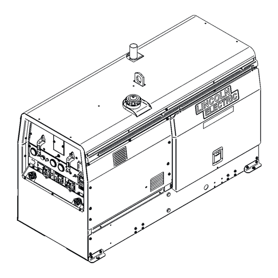
Page 8: Installation
INSTALLATION TECHNICAL SPECIFICATIONS - BIG RED™ 600 (K2811-1) INPUT - DIESEL ENGINE Make/Model Description Speed (RPM) Displacement Starting Capacities System Deutz 3 cylinder Idle 1890 173 cu. in 12VDC battery Fuel F3L 912 44HP (33 kw) (2.83L) & Starter (20 US gal) Diesel Engine @ 1800 RPM Full Load 1800... -
Page 9: Safety Precautions
INSTALLATION SAFETY PRECAUTION ANGLE OF OPERATION Read this entire installation section before you start To achieve optimum engine performance the BIG installation. RED™ 600 should be run in a level position. The maximum angle of operation for the Deutz engine is WARNING 30 degrees fore and aft, 40 degrees right and 45 degrees left. -
Page 10: Towing
INSTALLATION TOWING PRE-OPERATION ENGINE SERVICE READ the engine operating and maintenance instruc- Use a recommended trailer for use with this tions supplied with this machine. equipment for road, in-plant and yard towing by a vehicle(1). If the user adapts a non-Lincoln trailer, he WARNING must assume responsibility that the method of attachment and usage does not result in a safety... -
Page 11: Engine Break-In
INSTALLATION ENGINE BREAK-IN BATTERY CONNECTION WARNING Lincoln Electric selects high quality, heavy-duty industrial engines for the portable welding machines GASES FROM BATTERY can explode. we offer. While it is normal to see a small amount of crankcase oil consumption during initial operation, •... -
Page 12: Muffler Outlet Pipe
INSTALLATION MUFFLER OUTLET PIPE MACHINE GROUNDING Remove the plastic plug covering the muffler outlet Because this portable engine driven welder creates tube. Using the clamp provided secure the outlet pipe its own power, it is not necessary to connect its to the outlet tube with the pipe positioned such that it frame to an earth ground, unless the machine is will direct the exhaust in the desired position... -
Page 13: Auxiliary Power Receptacles
INSTALLATION AUXILIARY POWER RECEPTACLES RESIDUAL CURRENT DEVICE READY The auxiliary power of the BIG RED™ 600 consists of The BIG RED™ 600 is configured to allow for the Single Phase 60Hz Power. Output Voltage is within addition of a Residual Current Device (RCD) to pro- +/- 10% at loads up to rated capacity. -
Page 14: Connection Of Lincoln Electric Wire Feeders
INSTALLATION CONNECTION OF LINCOLN ELECTRIC WARNING WIRE FEEDERS If you are using an LN-25™ without an internal contactor, the electrode will be energized when WARNING the BIG RED™ 600 is started. ------------------------------------------------------------- Shut off Welder before making any electrical con- The Wire Feeder sensor has full OCV potential nections. -
Page 15: Operation
OPERATION SAFETY INSTRUCTIONS GENERAL DESCRIPTION Read and understand this entire section before The BIG RED™ 600 is a diesel engine driven welder, offering reliable DC arc welding performance, with operating your BIG RED™ 600. outstanding arc characteristics for all welding appli- cations. -
Page 16: Controls And Settings
OPERATION CONTROLS AND SETTINGS low. All welder and engine controls are located on the case front panel. Refer to Figure B.1 and the explanations that fol Figure B.1 Case Front Panel Controls 2. OUTPUT CONTROL WELDING CONTROLS (Items 1-5) Provides fine adjustment of the current and open 1. -
Page 17: Engine Controls
OPERATION 5. LOCAL / REMOTE CONTROL SWITCH and 11. OIL PRESSURE GAUGE REMOTE RECEPTACLE An indicator of engine oil pressure. The toggle switch provides the option of controlling the welding output at the control panel or remotely. 12. ENGINE PROTECTION For control at the control panel set the switch in the "LOCAL"... -
Page 18: Engine Operation
OPERATION 17. 120 VAC DUPLEX RECEPTACLE 8. Allow the engine to warm up for several minutes before applying a load. Allow a longer warm up 120VAC (5-20R) NEMA Duplex Receptacle. time in cold weather. Receptacle is GFCI protected. COLD WEATHER STARTING 18. -
Page 19: Arc Gouging
OPERATION WELDER OPERATION For example: to obtain 175 amps and a forceful arc, set the “Output Range Selector” to the 150-330 posi- tion and the “Output Current Adjustment” setting to DUTY CYCLE get 175 amps. Duty Cycle is the percentage of time the load is being applied in a 10 minute period. -
Page 20: Tig Welding
OPERATION The BIG RED™ 600 can be used for Scratch-Start of DC TIG welding applications. Use the “Output Range Selector” and “Output Control Adjustments” to set the desired current. To initiate a weld, the tungsten electrode is then scratched on the work which establishes the arc. To stop the arc, simply lift the TIG torch away from the work piece. - Page 21 OPERATION CONSTANT CURRENT OPERATION WITH Even if the voltage and current remain unchanged, the increased wire feed speed may result in a deposi- A LINCOLN ELECTRIC WIRE FEEDER tion rate well beyond the specified range of the elec- trode. Under these conditions, the specified weld Lincoln Electric does NOT recommend constant metal properties may not be achieved.
-
Page 22: Auxiliary Power
OPERATION AUXILIARY POWER: The auxiliary power is independent of the welding power and thus not effected by the weld control settings. Simultaneous Welding and Auxiliary Power Loads The auxiliary power ratings are with no welding load. Simultaneous welding and power loads are specified in the following Table B.4. -
Page 23: Accessories
ACCESSORIES OPTIONAL FEATURES K2641-2 FOUR WHEELED STEERABLE YARD TRAILER For in plant and yard towing. Comes standard with a Duo-Hitch™, a 2” Ball and Lunette Eye combination Hitch. K2636-1 TRAILER - Two-wheeled trailer with option- fender and light package. For highway use, consult applicable federal, state, and local laws regarding possible additional requirements. -
Page 24: Maintenance
MAINTENANCE SAFETY PRECAUTIONS WEEKLY Blow out the machine with low pressure air periodi- WARNING cally. In particularly dirty locations, this may be required once a week. Have qualified personnel do the maintenance work. Turn the engine off before working inside ENGINE MAINTENANCE the machine. -
Page 25: Oil Filter Change
MAINTENANCE Use motor oil designed for diesel engines that meets 3. Remove loose dirt from element with compressed requirements for API service classification air or water hose directed from inside out. CC/CD/CE/CF/CF-4/CG-4 or CH-4. Compressed Air: 100 psi maximum with nozzles at least one inch away from ACEA E1/E2/E3. -
Page 26: Fuel Filters
MAINTENANCE FUEL FILTERS 5. Brush off any debris and rinse in diesel fuel. WARNING 6. Re-install the pre-filter screen into the upper cavity of the filter header making sure the four pull tabs When working on the fuel system are pointing up. Putting your fingers on the pull tabs, push down evenly until the lower body of the •... -
Page 27: Second Fuel Filter
MAINTENANCE 5. Slide the quick change ring up over the element and BATTERY HANDLING rotate counter clockwise until an audible click or pop GASES FROM BATTERY can explode. is heard. If you do not hear the click you have not •... -
Page 28: Servicing Optional Spark Arrestor
MAINTENANCE SERVICING OPTIONAL SPARK PREVENTING BATTERY BUCKLING ARRESTOR Tighten nuts on battery clamp until snug. Clean every 100 hours. CHARGING THE BATTERY WARNING When you charge, jump, replace, or otherwise connect bat- tery cables to the battery, be sure the polarity is correct. •... -
Page 29: Welder / Generator Maintenance
MAINTENANCE WELDER / GENERATOR MAINTENANCE STORAGE Store the BIG RED™ 600 in clean, dry protected areas. CLEANING Blow out the generator and controls periodically with low pressure air. Do this at least once a week in particularly dirty areas. BRUSH REMOVAL AND REPLACEMENT It is normal for the brushes and slip rings to wear and dark- en slightly. -
Page 30: Troubleshooting
TROUBLESHOOTING HOW TO USE TROUBLESHOOTING GUIDE WARNING Service and Repair should only be performed by Lincoln Electric Factory Trained Personnel. Unauthorized repairs performed on this equipment may result in danger to the technician and machine operator and will invalidate your factory warranty. For your safety and to avoid Electrical Shock, please observe all safety notes and precautions detailed throughout this manual. - Page 31 TROUBLESHOOTING Observe all Safety Guidelines detailed throughout this manual PROBLEMS POSSIBLE RECOMMENDED (SYMPTOMS) CAUSE COURSE OF ACTION Major Physical or Electrical Damage 1. Contact your Local Lincoln is Evident. Authorized Field Service Facility. Engine will not crank 1. Battery low. 2.
- Page 32 TROUBLESHOOTING Observe all Safety Guidelines detailed throughout this manual PROBLEMS POSSIBLE RECOMMENDED (SYMPTOMS) CAUSE COURSE OF ACTION Engine shuts down while under a 1. High oil temperature. load. Engine runs rough. 1. Dirty fuel or air filters may need cleaned/replaced. 2.
-
Page 33: Diagrams
DIAGRAMS BIG RED™ 600... - Page 34 DIAGRAMS...
- Page 35 DIAGRAMS BIG RED™ 600...
- Page 36 DIAGRAMS BIG RED™ 600...
- Page 37 DIAGRAMS BIG RED™ 600...
- Page 38 Do not touch electrically live parts or Keep flammable materials away. Wear eye, ear and body protection. ● ● ● WARNING electrode with skin or wet clothing. Insulate yourself from work and ● ground. Spanish No toque las partes o los electrodos Mantenga el material combustible Protéjase los ojos, los oídos y el ●...
- Page 39 Keep your head out of fumes. Turn power off before servicing. Do not operate with panel open or ● ● ● Use ventilation or exhaust to remove guards off. WARNING ● fumes from breathing zone. Spanish Los humos fuera de la zona de res- ●...
- Page 40 CUSTOMER ASSISTANCE POLICY The business of The Lincoln Electric Company is manufacturing and selling high quality welding equipment, consumables, and cutting equipment. Our challenge is to meet the needs of our customers and to exceed their expectations. On occasion, purchasers may ask Lincoln Electric for advice or information about their use of our products.
Need help?
Do you have a question about the BIG RED 600 and is the answer not in the manual?
Questions and answers