Table of Contents

Subscribe to Our Youtube Channel
Related Manuals for Ecreso Helios FM 20/100 W


Summary of Contents for Ecreso Helios FM 20/100 W
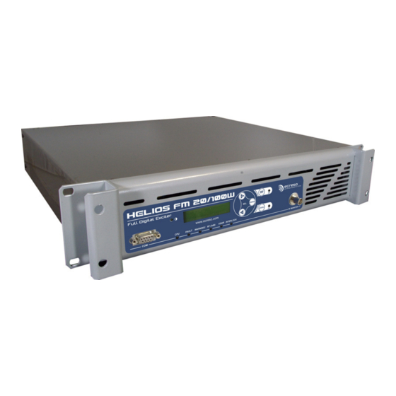
- Page 1 Helios FM 20/100 W User manual 87.5 – 108 MHz 20 OR 100 W STEREO AND MULTIPLEX COMPACT FM DIGITAL TRANSMITTER WITH TCP/IP MONITORING* *depending on options Date: 2011/12/05 ecreso WorldCast Systems Group web: www.ecreso.com - e-mail: contact@ecreso.com...
-
Page 2: Table Of Contents
Helios FM 20/100 W, user manual– 12/2011 TABLE OF CONTENTS 1. INTRODUCTION ..........................4 1.1. About Ecreso ..........................4 1.2. Before you start .......................... 5 2. DESCRIPTION ............................ 6 2.1. General description ........................6 ... - Page 3 Helios FM 20/100 W, user manual– 12/2011 5.3.14. C OM Menu .......................... 32 5.3.15. P ower supply Menu ......................33 5.3.16. T emp/Fan Menu ........................34 5.3.17. T ime/Date Menu ........................35 ...
-
Page 4: Introduction
ECRESO offers analog and digital radio as well as digital TV transmitters (FM, DAB, DAB+, T-DMB, DVB- T/H), low power transmitters, which are air-cooled, as well as high power devices either air or water-cooled. -
Page 5: Before You Start
Helios FM 20/100 W, user manual– 12/2011 1.2. Before you start This equipment complies with international mechanical and electrical standards. To maintain this compliance, as well as to ensure proper and safe working conditions and avoid electrical shocks and fire hazards, you must comply with the following recommendations: 1 - The device should only be utilized in the conditions described in the user manual. -
Page 6: Description
The manufacturing quality and the simplicity of use make these truly powerful transmitters to broadcast analog FM programs. The Helios FM 20/100 W is fully protected against overheating, VSWR and lightning. In addition, several innovative features are available, such as RDS encoding and automated audio backup. -
Page 7: Helios Fm 20/100 W Description
Helios FM 20/100 W, user manual– 12/2011 2.2. Helios FM 20/100 W Description 2.2.1. Front panel LCD contrast LCD display Navigation RF monitoring output keys RS232 port Indicators: CPU, Fault, on/off Warning, RF (3 dB), local mode keys VSWR and Interlock... -
Page 8: Rear Panel
Helios FM 20/100 W, user manual– 12/2011 2.2.2. Rear panel N RF output Communication MPX/SCA1 Audio input Line1 Mains board (option) * MPX/SCA2 (Ana or AES) 19 kHz Interlock GPIO slot Ground Audio input Line2 (option) (Ana or AES) * Two optional communication boards are available: TCP/IP board •... -
Page 9: Opened Cover
Helios FM 20/100 W, user manual– 12/2011 2.2.3. Opened cover Optional Audio inputs communication board Optional GPIO board Mains filter RF amplifier bloc Surge protection (non present option) Digital modulator Low voltage power bloc High output Control board power supply Page 9 Head Office : Parc d’activites Kennedy - 20, avenue Neil Armstrong –... -
Page 10: Synoptic
Helios FM 20/100 W, user manual– 12/2011 2.2.4. Synoptic Helios FM 20/100 W Audio Audio 1 AES1 Audio 2 Audio/IP AES2 Tuner Internal player 19 kHz output Page 10 Head Office : Parc d’activites Kennedy - 20, avenue Neil Armstrong – F-33700 Bordeaux-Merignac (France) Tel +33 (0)5 57 928 928 –... -
Page 11: Rack
Helios FM 20/100 W, user manual– 12/2011 2.2.5. 2U Rack The choice of stainless steel as material guarantees against corrosion. The rack structure and the structure of the monoblock front panel reinforce the device. The rectangular outline of the rounded front panel has a large LCD display protected by armored glass. -
Page 12: Technical Specifications
Helios FM 20/100 W, user manual– 12/2011 3. TECHNICAL SPECIFICATIONS 3.1. RF section Frequency range 87.5 to 108 MHz Summary of different steps 10 kHz Frequency stability < 10 per year Power range 0-20 W or 0-100 W @ ROS=1.35... -
Page 13: Af Inputs
Helios FM 20/100 W, user manual– 12/2011 3.5. AF inputs Analog (LINE1) Connector "XLR" type Impedance > 10 kΩ by default, adjustable to 600 Ω by jumpers, unbalanced Bandwidth Software adjustable Level Software adjustable (-18/+18 dBu range) AES (LINE2) Connector "XLR"... -
Page 14: Interface Panel
Helios FM 20/100 W, user manual– 12/2011 3.8. Interface panel Indicators Green LED: CPU activity Red LED: major fault Yellow LED: minor fault Red LED: RF fault (3 dB) Red LED: VSWR fault Green LED: safety interlock Screens Back lighted LCD: displays operating parameters and menus. -
Page 15: Starting Up Your Transmitter
The 50 Ω charge power must be greater than 30 W for a 20 W transmitter and greater than 150 W for a 100 W transmitter. When you acquired your Helios FM 20/100 W, the RF amplifier is deactivated and power is set to 0 W. These settings can be adjusted using the PC application, the front panel application or serial commands. -
Page 16: Setting The Transmitter
Helios FM 20/100 W, user manual– 12/2011 4.2. Setting the transmitter On the PC, start the control software. This is a set-up tool that will allow you to quickly set and test your transmitter. All settings and measurements are also available on the front panel screen and with serial commands. -
Page 17: Input Selection
Helios FM 20/100 W, user manual– 12/2011 4.3. Input selection The input can be set to: • Line1 for the analog inputs (see sections 4.5 to 4.7) • Line2 for the AES (see sections 4.5 to 4.7) • MPX1 and MPX2 inputs (see sections 4.4 and 4.7) •... -
Page 18: Front Screen Use
Helios FM 20/100 W, user manual– 12/2011 5. FRONT SCREEN USE 5.1. Overview The transmitter can be entirely set using the front panel application. For audio configuration you will use the following menus: • Input Select: to select the main audio source and the secondary audio sources. - Page 19 Helios FM 20/100 W, user manual– 12/2011 Some menus include sub-menus. To make it easier to browse through the menus and locate the information, a small number is visible on the top left of the screen; it gives you the level of the menu you are viewing...
-
Page 20: Structure Of The Menus
Helios FM 20/100 W, user manual– 12/2011 5.3. Structure of the menus 5.3.1. First level measurements These values are read-only; bargraphs may also be available. 9 8 . 0 0 M H z 1 0 0 W ENTER ||| ||| ||| ||| ||| ||| ||| ||| ||| ||| ||| ||| ||| P r = V S W R = 1 . -
Page 21: First Level Menus
Helios FM 20/100 W, user manual– 12/2011 5.3.2. First level menus 9 8 . 0 0 M H z 1 0 0 W ||| ||| ||| ||| ||| ||| ||| ||| ||| ||| ||| ||| ||| ENTER 9 8 . 0 0 M H z 1 0 0 W ->... -
Page 22: Tx Parameters Menu
Helios FM 20/100 W, user manual– 12/2011 5.3.3. TX PARAMETERS Menu 9 8 . 0 0 M H z 1 0 0 W -> T X P A R A M E T E R S > ENTER F R E Q P F W D ->... -
Page 23: Input Select Menu
Helios FM 20/100 W, user manual– 12/2011 5.3.5. INPUT SELECT Menu 9 8 . 0 0 M H z 1 0 0 W -> I N P U T S E L E C T > ENTER I N P U T S E L E C T ->... -
Page 24: Input Switch Menu
Helios FM 20/100 W, user manual– 12/2011 5.3.6. INPUT SWITCH Menu 9 8 , 0 0 M H z 1 0 0 W -> I N P U T S W I T C H > ENTER I N P U T S W I T C H ->... -
Page 25: Line1 Menu
Helios FM 20/100 W, user manual– 12/2011 5.3.7. LINE1 Menu (similar to the Line2 menu) 9 8 . 0 0 M H z 1 0 0 W -> L I N E 1 > ENTER L I N E 1 P R E S E N C E : L &... -
Page 26: Mpx In Menu
Helios FM 20/100 W, user manual– 12/2011 5.3.8. MPX in Menu 9 8 . 0 0 M H z 7 5 0 W -> M P X I N > ENTER M P X -> M P X 1 >... -
Page 27: Audio Gene Menu
Helios FM 20/100 W, user manual– 12/2011 5.3.9. Audio Gene Menu 9 8 . 0 0 M H z 1 0 0 W -> A U D I O G E N E > ENTER A U D I O G E N E ->... -
Page 28: Modulation Menu
Helios FM 20/100 W, user manual– 12/2011 5.3.10. Modulation Menu 9 8 . 0 0 M H z 7 5 0 W -> M O D U L A T I O N > ENTER M O D U L A T I O N... -
Page 29: Stereo Encoder Menu
Helios FM 20/100 W, user manual– 12/2011 5.3.11. Stereo encoder Menu 9 8 . 0 0 M H z 7 5 0 W -> S T E N C O D E R > ENTER E N C O D E R ->... -
Page 30: Rds Menu
Helios FM 20/100 W, user manual– 12/2011 5.3.12. RDS Menu 9 8 . 0 0 M H z 1 0 0 W -> R D S > ENTER R D S C U R R E N T : M A I N ( 1 ) R D S ->... -
Page 31: Network Menu
Helios FM 20/100 W, user manual– 12/2011 5.3.13. Network Menu 9 8 . 0 0 M H z 1 0 0 W -> N E T W O R K > ENTER N E T W O R K -> A D R ->... -
Page 32: Com Menu
Helios FM 20/100 W, user manual– 12/2011 5.3.14. COM Menu 9 8 . 0 0 M H z 1 0 0 W -> C O M > ENTER L O C A L C O M S P E E D ->... -
Page 33: Power Supply Menu
Helios FM 20/100 W, user manual– 12/2011 5.3.15. Power supply Menu 9 8 . 0 0 M H z 1 0 0 W -> P O W E R S U P P L Y > ENTER C U R 1 : 2 1 . -
Page 34: Temp/Fan Menu
Helios FM 20/100 W, user manual– 12/2011 5.3.16. Temp/Fan Menu 9 8 . 0 0 M H z 7 5 0 W -> T E M P / F A N > ENTER T ° A M B : 3 1 ° C T °... -
Page 35: Time/Date Menu
Helios FM 20/100 W, user manual– 12/2011 5.3.17. Time/Date Menu 9 8 . 0 0 M H z 1 0 0 W -> T I M E / D A T E > ENTER 1 4 : 0 4 2 3 / 0 6 / 1 1 ->... -
Page 36: About Menu
Helios FM 20/100 W, user manual– 12/2011 5.3.18. About Menu 1 0 4 . 0 5 M H z 7 5 0 W -> A B O U T > ENTER S Y S T Y P E : H 1 0... -
Page 37: Exit Menu
Helios FM 20/100 W, user manual– 12/2011 5.3.19. Exit Menu 0 0 M H z 1 0 0 W -> E X I T ENTER 9 8 . 0 0 M H z 1 0 0 W ||| ||| ||| ||| ||| ||| ||| ||| ||| ||| ||| ||| |||... -
Page 38: Parameters Description
Helios FM 20/100 W, user manual– 12/2011 5.4. Main parameters description Parameters are described for the main menus; serial commands are indicated in parenthesis. Possible values and/or value format are indicated for each parameter. 5.4.1. INPUT SELECT Menu These parameters are available as INPUT serial commands (see section 6.2.5), but are managed differently: the PRIO parameter for each input sets the selection order for the various audio sources. -
Page 39: Menu Line 1 (Ana)
Helios FM 20/100 W, user manual– 12/2011 DELAY (INPUT.xx.SW.DELAY) – read/write With this parameters, set the switching delay in seconds when audio loss occurs. From 1 to 120 s BACK DELAY (INPUT.xx.SW.BACKDELAY) – read/write With this parameters, set the delay before returning to the highest priority channel, in seconds. -
Page 40: Line 2 Menu (Aes)
Helios FM 20/100 W, user manual– 12/2011 protection. Select 0 kHz to disable the filter: this solution can be used in mono operation (in stereo operation, the incidence on the MPX signal and its sub-carrier would be too great) or when a 15 kHz filter is already used upstream as with an FM processor for instance. -
Page 41: Audio Gene Menu
Helios FM 20/100 W, user manual– 12/2011 measurements on the front panel to read the MPXn LEVEL. Be aware that if the level is poorly set the deviation may become too low or too high. This level is also called nominal level, i.e. the level producing the deviation as set in the Modulation menu. -
Page 42: Modulation Menu
Helios FM 20/100 W, user manual– 12/2011 5.4.7. MODULATION Menu These parameters are available as MEAS.DEV and CONF serial commands (see section 6.2.2 and 6.2.3). RMS (MEAS.DEV.RMS) – read only This parameter indicates the average value of the transmitted signal’s excursion in kHz. -
Page 43: Stereo Encoder Menu
Helios FM 20/100 W, user manual– 12/2011 SCA STATE (CONF. STATE.SCA) – read/write With this parameter, enable or disable the SCA. When the SCA is enabled or disabled, the SCA deviation is automatically subtracted from or added to the audio deviation to maintain the same total deviation. -
Page 44: Rds Menu
Helios FM 20/100 W, user manual– 12/2011 19k OUT LEVEL (CODER.19KOUT.LEVEL) – read/write With this parameter, enable/disable the rear panel 19 kHz clock and set its output level. 0=off; between 1 and 7: set a level between 0.9 and 1.1 V peak-to-peak. 5 corresponds to 1 V. - Page 45 Helios FM 20/100 W, user manual– 12/2011 PTY (RDS.MAINDSN.PTY) – read/write With this parameter, set the PTY (Program Type). Select on 32 RDS or RDBS preset codes as given in the table below. From 0 to 31 PTY code RDS Programme type (EU)
- Page 46 Helios FM 20/100 W, user manual– 12/2011 PS (RDS.MAINDSN.PS) – read/write With this parameter, set the PS (Program Station) 8-digit code MS (RDS.MAINDSN.MS) – read/write With this parameter, indicate whether the program is Music or Speech to automatically adjust the sound level of the RDS receiver.
- Page 47 Helios FM 20/100 W, user manual– 12/2011 AF (RDS.MAINDSN.AF) – read/write With this parameter, set up to 25 alternative frequencies in MHz with the method A. A RDS receiver will shift to an alternative frequency when the set frequency is no longer properly received.
-
Page 48: Serial Commands
Helios FM 20/100 W, user manual– 12/2011 6. SERIAL COMMANDS 6.1. Working principle Helios FM 20100 W has a serial interface. The physical connection is done using the SUB-D9 (SERIAL MONITOR) on the front panel. A common computer with an RS 232 interface (example: PC+ Windows + Hyper-Terminal) is all you need to send commands. -
Page 49: Serial Commands
Helios FM 20/100 W, user manual– 12/2011 6.2. Serial commands 6.2.1. System commands Access Possible value on the serial port NAME Comments (R/W) of the unit SYS.RST Reset of all parameters. General reset of the µc. Sends the return SYS.RST.CPU "RST"... -
Page 50: Measurement Commands
Helios FM 20/100 W, user manual– 12/2011 Access Possible value on the serial port NAME Comments (R/W) of the unit Sets the RM control either by the control board or manually. Hexadecimal code: each SYS.GPIO.OUT.MASK XX X=[A..F;0..9] corresponds input: (00100001) indicates RM 1 and 6 are managed manually. -
Page 51: Alarm Commands
Helios FM 20/100 W, user manual– 12/2011 6.2.4. Alarm commands Access Possible value on the serial NAME Comments (R/W) port of the unit ALARM.AMB "ON" or "OFF" ON => ambient alarm, OFF => No alarm. ALARM.BATLOW "ON" or "OFF" Indicates if the NVRAM battery’s level is OK... - Page 52 Helios FM 20/100 W, user manual– 12/2011 Access Possible value on the NAME Comments (R/W) serial port of the unit INPUT.LINE2.FLT 0;1;2 0=15;1=16;2=17 Configuration of the audio filter INPUT.LINE2.PREAC 0;50;75 Sets the value of the pre-emphasis Internal numerical gain. For AES, between -20 and INPUT.LINE2.LEVEL...
-
Page 53: Encoder Commands
Helios FM 20/100 W, user manual– 12/2011 Access Possible value on the NAME Comments (R/W) serial port of the unit INPUT.MPX2.SW.PRIO 0..7 ; 0=disabled Priority of each audio channel (4= highest priority) "OFF" or "L" or "R" or "L+R" INPUT.AUDIOGEN.STATE Type of generated MPX signal or "L-R"... -
Page 54: Rds Commands
Helios FM 20/100 W, user manual– 12/2011 6.2.7. RDS commands Access Possible value on the serial NAME Comments (R/W) port of the unit Enables RDS to identify the station when searching the RDS.MAINDSN.PI XXXX X=[0..9;A…F] frequency using AF or EON-AF code RDS.MAINDSN.PS... -
Page 55: Transmitter Commands
Helios FM 20/100 W, user manual– 12/2011 6.2.8. Transmitter commands Access Possible value on the serial NAME Comments (R/W) port of the unit TX.NAME XXXX X=[A…Z] Transmitter name Working frequency of the modulator in kHz "232553" => TX.FREQ XXXXXX 232.553 MHz Sets the triggering threshold for the 3 dB alarm. -
Page 56: Communication Board Commands
Helios FM 20/100 W, user manual– 12/2011 6.2.10. Communication board commands Access Possible value on the serial port NAME Comments (R/W) of the unit Gateway between the serial port and the CAN bus. ID,CMD,DATA ; ID=[0…9]; ID=recipient’s address; TABLE=table containing CMD=[0…FF] DATA=[0..9 ;... -
Page 57: Hyperterminal Connection
Helios FM 20/100 W, user manual– 12/2011 6.3. HyperTerminal connection With Windows 95/98/2000/XP/Vista/7, launch the HyperTerminal: Start > Programs > Accessories > Communication > HyperTerminal. The following window appears: Connection description Enter the connection name and click OK. It is recommended to enter the device name you want to contact. - Page 58 Helios FM 20/100 W, user manual– 12/2011 The next window appears: Connection Select the serial port with which you want to connect to the equipment, then click OK. Enter the port parameters as indicated, and click OK. Page 58 Head Office : Parc d’activites Kennedy - 20, avenue Neil Armstrong – F-33700 Bordeaux-Merignac (France) Tel +33 (0)5 57 928 928 –...
- Page 59 Helios FM 20/100 W, user manual– 12/2011 Port settings You connection has been established, you can directly communicate with the device connected to the serial port of your computer. You can launch the commands described in this chapter. Typing the INFO command, the device must display the following information (connected to a Goliath in this example).
-
Page 60: Remote Control And Monitoring With The Gpio Board
This function is available when the optional GPIO board is installed on the transmitter. It provides an interface between ECRESO transmitters and external systems. The modules are remotely controlled via “RC” inputs using opto isolators. Working state and alarms are sent to “RM” outputs via relays. -
Page 61: Remote Monitoring Function Pinout
Helios FM 20/100 W, user manual– 12/2011 7.4. Remote monitoring function pinout Event Remote Monitoring Output name Common LOCAL REL1_RT(1) REL1_C(14) FAULT REL2_RT(2) REL2_C(15) WARNING REL3_RT(3) REL3_C(16) RF (ON/OFF or 3DB REL4_RT(4) REL4_C(17) or both) REL5_T(5) REL5_C(6) REL5_R(5) REL5_C(6) VSWR... -
Page 62: Physical Representation Of The Gpios
Helios FM 20/100 W, user manual– 12/2011 7.5. Physical representation of the GPIOs 12 V floating TC COMMON power supply Page 62 Head Office : Parc d’activites Kennedy - 20, avenue Neil Armstrong – F-33700 Bordeaux-Merignac (France) Tel +33 (0)5 57 928 928 – Fax +33 (0)5 57 928 929 –... -
Page 63: Management Using The Optional Tcp/Ip Board
Helios FM 20/100 W, user manual– 12/2011 7.6. Management using serial commands A set of commands makes it possible to override the control board to modify specific RC outputs and read specific RM inputs. To do so, set the RC you want to control (SYS.GPIO.IN.MASK) and the RM you want information from (SYS.GPIO.OUT.MASK). - Page 64 Helios FM 20/100 W, user manual– 12/2011 However, the format of values returned by serial commands is hexadecimal. You must then convert each 4 digit set as per the following table: Hexadecimal Binary 0000 0001 0010 0011 0100 0101 0110...
-
Page 65: The Embedded Website
Helios FM 20/100 W, user manual– 12/2011 8. THE EMBEDDED WEBSITE 8.1. Introduction This function is available with the IP/IO version when the optional TCP/IP board is installed on the transmitter. 8.2. Connecting to the embedded web site For remote access, connect to the transmitter’s embedded web site. Simply open a web browser (Google Chrome, Mozilla Firefox …) and enter the transmitter’s IP address in the address bar (default:... -
Page 66: Viewing The Status
Helios FM 20/100 W, user manual– 12/2011 The indicator on the right enables all connected users to know about current notifications: No current notification A notification has been sent A notification has been processed 8.3. Viewing the Status This page displays the main parameters of the transmitter (read-only). - Page 67 Helios FM 20/100 W, user manual– 12/2011 8.4. Configuration This page displays the main parameters of the transmitter so they can be updated. When values have been changed, click the button to save the new settings. If the transmitter is in local mode (green LED), Check the Local LED before making changes or you may not be able to save: Local mode, modifications cannot be saved.
- Page 68 Helios FM 20/100 W, user manual– 12/2011 8.5. System Click the Save button to lock in your changes; this is true for every page of the system configuration. 8.5.1. Product ID General information regarding the product: name, serial number, versions…...
- Page 69 Helios FM 20/100 W, user manual– 12/2011 8.5.2. Date / Time Set system date: the user may update both date (year/month/day) and time (hour/minute/second). Set system time zone: The user selects the geographical zone from the list. Important to have this set correctly when using an NTP server.
- Page 70 Helios FM 20/100 W, user manual– 12/2011 8.5.3. Users This is where web site connection settings can be modified. This page is only visible to administrators. Two web and software accounts are available: • Administrator (Admin / admin by default). The administrator has full rights •...
- Page 71 Helios FM 20/100 W, user manual– 12/2011 8.5.4. Network IP Configuration: Static Ethernet configuration Set the parameters for the network interface. DNS Servers: DNS configuration. Mandatory if before using DNS addresses on other configuration pages. Page 71 Head Office : Parc d’activites Kennedy - 20, avenue Neil Armstrong – F-33700 Bordeaux-Merignac (France) Tel +33 (0)5 57 928 928 –...
- Page 72 Helios FM 20/100 W, user manual– 12/2011 8.5.5. Support With the ‘Reboot TCP/IP option’ button, restart the TCP/IP board. With the ‘Reboot Transmitter’ button, restart the transmitter’s front panel. Page 72 Head Office : Parc d’activites Kennedy - 20, avenue Neil Armstrong – F-33700 Bordeaux-Merignac (France) Tel +33 (0)5 57 928 928 –...
- Page 73 Helios FM 20/100 W, user manual– 12/2011 8.5.6. SNMP Agent SNMP configuration The equipment enables multiple addresses to be configured for SNMP notifications. However, only the Main Manager has the authority to acknowledge notifications. With “INFORMS” messages, automatic answers from secondary managers are ignored by the unit.
- Page 74 Helios FM 20/100 W, user manual– 12/2011 8.5.6.1 Supported SNMP versions The unit implements an SNMP agent conforming to SNMPv1 and SNMPv2c versions. GET and SET commands are supported, as well as GETBULK in SNMPv2c. Notifications can be transmitted in TRAP V1 or V2c form or with an INFORM V2c type.
- Page 75 Helios FM 20/100 W, user manual– 12/2011 8.5.7. Notifications SNMP Actions The user may replay traps that have not been acknowledged yet. The user may also delete pending traps that have not been acknowledged yet. Page 75 Head Office : Parc d’activites Kennedy - 20, avenue Neil Armstrong – F-33700 Bordeaux-Merignac (France) Tel +33 (0)5 57 928 928 –...
- Page 76 Helios FM 20/100 W, user manual– 12/2011 8.5.8. Common traps Click the arrow next to the trap name to display its parameters. To enable the trap, check "Enabled". Set the mode: • Resend until acknowledgement: the trap is regularly sent until acknowledgement.
-
Page 77: Irt Traps
Helios FM 20/100 W, user manual– 12/2011 8.5.9. IRT Traps IRT traps are configured like common traps (see previous section). Page 77 Head Office : Parc d’activites Kennedy - 20, avenue Neil Armstrong – F-33700 Bordeaux-Merignac (France) Tel +33 (0)5 57 928 928 – Fax +33 (0)5 57 928 929 –... - Page 78 Helios FM 20/100 W, user manual– 12/2011 8.5.10. Ecreso Traps Ecreso traps are configured like common traps (see section 8.5.8). No trap is sent on automatic audio switch. 8.6. About This window displays information regarding the web application Page 78 Head Office : Parc d’activites Kennedy - 20, avenue Neil Armstrong –...
-
Page 79: Annexe A
Helios FM 20/100 W, user manual– 12/2011 APPENDIX A: ADJUSTING THE IMPEDANCE OF ANALOG INPUTS Default impedance of analog inputs is 10 kΩ. It can be set to 600 Ω by jumpers. Before setting the jumpers, make sure that all cables are disconnected. Remove all the screws securing the cover. -
Page 80: For More Information
Helios FM 20/100 W, user manual– 12/2011 FOR MORE INFORMATION Please contact: Ecreso 20, avenue Neil Armstrong - Parc d'Activités J.F. Kennedy 33700 BORDEAUX – MERIGNAC FRANCE Tel: +33 (5)57 928 928 | Fax: +33 (5)57 928 929 Hotline: support@audemat.com...
Need help?
Do you have a question about the Helios FM 20/100 W and is the answer not in the manual?
Questions and answers