Table of Contents
Advertisement
Advertisement
Table of Contents

Related Manuals for Brovision WH-N5204-P4

Summary of Contents for Brovision WH-N5204-P4
- Page 1 Network Video Recorder User Manual...
- Page 2 User Manual of Network Video Recorder Regulatory information FCC information This equipment has been tested and found to comply with the limits for a digital device, pursuant compliance: to part 15 of the FCC Rules. These limits are designed to provide reasonable protection against harmful interference when the equipment is operated in a commercial environment.
-
Page 3: Preventive And Cautionary Tips
User Manual of Network Video Recorder Preventive and Cautionary Tips Before connecting and operating your device, please be advised of the following tips: • Ensure unit is installed in a well-ventilated, dust-free environment. • Unit is designed for indoor use only. •... - Page 4 Thank you for purchasing our product. If there is any question or request, please do not hesitate to contact dealer. The figures in the manual are for reference only. This manual is applicable to the models listed in the following table. Series Model Type WH-N5xxx WH-N5204-P4 Network Video Recorder WH-N5208-P8 WH-N5316-P16...
- Page 5 Zooming in by clicking the mouse and PTZ tracing by dragging mouse. HDD Management For WH-N5204-P4 series, 1 SATA hard disks can be connected; For WH-N5208-P8 series, 2 SATA hard disks can be connected; For WH-N5316-P16 series, 4 SATA hard disks can be connected;...
- Page 6 User Manual of Network Video Recorder and manual recording. Searching record files and captured pictures by events (alarm input/motion detection). Tag adding for record files, searching and playing back by tags. Locking and unlocking record files. Local redundant recording and capture. ...
- Page 7 User Manual of Network Video Recorder Support accessing by the platform via ONVIF. Remote search, playback, download, locking and unlocking of the record files, and support downloading files broken transfer resume. Remote parameters setup; remote import/export of device parameters. ...
-
Page 8: Table Of Contents
User Manual of Network Video Recorder TABLE OF CONTENTS Chapter 1 Introduction ..........................11 Front Panel ............................ 12 Rear Panel ............................. 20 Chapter 2 Getting Started ......................... 22 Starting Up and Shutting Down the NVR ..................23 Using the Wizard for Basic Configuration..................25 Adding and Connecting the IP Cameras .................. - Page 9 User Manual of Network Video Recorder Configuring Redundant Recording and Capture ................78 Configuring HDD Group for Recording and Capture ..............80 5.10 Files Protection ..........................81 5.10.1 Locking the Recording Files ....................81 5.10.2 Setting HDD Property to Read-only ..................83 Chapter 6 Playback ............................
- Page 10 User Manual of Network Video Recorder 9.2.1 Configuring PPPoE Settings ....................148 9.2.2 Configuring DDNS ......................148 9.2.3 Configuring NTP Server ....................152 9.2.4 Configuring SNMP ......................152 9.2.5 Configuring Remote Alarm Host ..................153 9.2.6 Configuring Multicast ......................154 9.2.7 Configuring RTSP ......................
- Page 11 User Manual of Network Video Recorder 12.2 Searching & Export Log Files ..................... 195 12.3 Importing/Exporting IP Camera Info ................... 198 12.4 Importing/Exporting Configuration Files ..................199 12.5 Upgrading System ........................200 12.5.1 Upgrading by Local Backup Device .................. 200 12.5.2 Upgrading by FTP ......................
-
Page 12: Chapter 1 Introduction
User Manual of Network Video Recorder Chapter 1 Introduction... -
Page 13: Front Panel
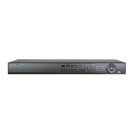
User Manual of Network Video Recorder 1.1 Front Panel Figure 1. 1 WH-N5204-P4 & WH-N5208-P8 Table 1. 1 Description of Control Panel Buttons Name Function Description POWER: the POWER indicator turns green when NVR is powered up. READY: The indicator light is green when the device is running normally. - Page 14 User Manual of Network Video Recorder Name Function Description Start/stop record clipping in playback. Enter numeral “6”; Enter letters “MNO”; 6/MNO/PLAY: Playback, for direct access to playback interface. Enter numeral “7”; Enter letters “PQRS”; 7/PQRS/REC: Open the manual record interface. Enter numeral “8”;...
- Page 15 User Manual of Network Video Recorder Figure 1. 2 WH-N5316-P16 Table 1. 2 Description of Control Panel Buttons Name Function Description POWER ON/OFF Power on/off switch. USB Interface Connect to USB mouse or USB flash memory. IR Receiver Receiver for IR remote control. devices. POWER Power indicator lights in green when DVR is powered up.
- Page 16 User Manual of Network Video Recorder Enter numeral “3”; Enter letters “DEF”; 3DEF/F2 In PTZ Control mode, the F1 button can be used to zoom in (zoom+) the PTZ camera; The F2 button can be used to cycle through tab pages. Enter numeral “4”;...
- Page 17 User Manual of Network Video Recorder IR Remote Control Operations The NVR may also be controlled with the included IR remote control, shown in Figure 1. 3. Batteries (2× AAA) must be installed before operation. Figure 1. 3 Remote Control The keys on the remote control closely resemble the ones on the front panel.
- Page 18 User Manual of Network Video Recorder Name Description VOIP/MON Button Same as the MAIN/SPOT/ZOOM- button on front panel. MENU Button Same as the MENU/WIPER button on front panel. Same as the PREV/FOCUS- button on front panel. PREV Button Same as the DIRECTION/ENTER buttons on front panel. DIRECTION/ENTER Buttons PTZ Button...
- Page 19 User Manual of Network Video Recorder USB Mouse Operation A regular 3-button (Left/Right/Scroll-wheel) USB mouse can also be used with this NVR. To use a USB mouse: Plug USB mouse into one of the USB interfaces on the front panel of the NVR. The mouse should automatically be detected.
- Page 20 User Manual of Network Video Recorder Input Method Description Figure 1. 4 Soft Keyboard (1) Figure 1. 5 Soft Keyboard (2) Description of the buttons on the soft keyboard: Table 1. 5 Description of the Soft Keyboard Icons Icon Description Icon Description Number...
-
Page 21: Rear Panel
User Manual of Network Video Recorder 1.2 Rear Panel Figure 1. 6 WH-N5204-P4 Figure 1. 7 WH-N5208-P8 Table 1. 6 Description of Rear Panel Interfaces Item Description Power Supply 48V DC power supply for 4ch NVR and AC 100~240V for 8ch and... - Page 22 User Manual of Network Video Recorder Figure 1. 8 WH-N5316-P16 Table 1. 7 Description of Rear Panel Interfaces Item Description VIDEO OUT BNC connector for video output. CVBS AUDIO OUT BNC connector for audio output. This connector is synchronized with CVBS video output.
-
Page 23: Chapter 2 Getting Started
User Manual of Network Video Recorder Chapter 2 Getting Started... -
Page 24: Starting Up And Shutting Down The Nvr
User Manual of Network Video Recorder 2.1 Starting Up and Shutting Down the NVR Purpose: Proper startup and shutdown procedures are crucial to expanding the life of the NVR. Before you start: Check that the voltage of the extra power supply is the same with the NVR‟s requirement, and the ground connection is working properly. - Page 25 User Manual of Network Video Recorder Rebooting the NVR In the Shutdown menu, you can also reboot the NVR. Steps: Enter the Shutdown menu by clicking Menu > Shutdown. Click the Logout button to lock the NVR or the Reboot button to reboot the NVR.
-
Page 26: Using The Wizard For Basic Configuration
User Manual of Network Video Recorder 2.2 Using the Wizard for Basic Configuration By default, the Setup Wizard starts once the NVR has loaded, as shown in Figure 2. 2. Figure 2. 2 Start Wizard Interface Operating the Setup Wizard: 1. - Page 27 User Manual of Network Video Recorder Figure 2. 4 Date and Time Settings 6. After the time settings, click Next button which takes you back to the Network Setup Wizard window, as shown in Figure 2. 5. Figure 2. 5 Network Configuration Dual-NIC is only supported in high enterprise level NVRs.
- Page 28 User Manual of Network Video Recorder Figure 2. 6 HDD Management 8. To initialize the HDD, click the Init button. Initialization removes all the data saved in the HDD. Click Next button. You enter the Adding IP Camera interface. Click Search to find online IP Camera. Select the IP camera to be added, and click the Add button. Figure 2.
- Page 29 User Manual of Network Video Recorder Figure 2. 9 Copy Record Settings Click OK to complete the startup Setup Wizard.
-
Page 30: Adding And Connecting The Ip Cameras
User Manual of Network Video Recorder 2.3 Adding and Connecting the IP Cameras 2.3.1 Adding the Online IP Cameras Purpose: The main function of the NVR is to connect the network cameras and record the video got from it. So before you can get a live view or record of the video, you should add the network cameras to the connection list of the device. - Page 31 User Manual of Network Video Recorder Figure 2. 11 Adding IP Camera Interface 3. The online cameras with same network segment will be displayed in the camera list. Click the button to add the camera. Or you can click the One-touch Adding button to add all the online IP cameras. Table 2.
- Page 32 User Manual of Network Video Recorder 2) You can edit the IP address, protocol, management port, and other information of the IP camera to be added. 3) Click Add to add the camera. OPTION 2: Steps: 1. Enter the Camera Management interface. Menu>...
-
Page 33: Editing The Connected Ip Cameras And Configuring Customized Protocols
User Manual of Network Video Recorder Figure 2. 15 Selecting Multiple Channels 2.3.2 Editing the Connected IP Cameras and Configuring Customized Protocols After the adding of the IP cameras, the basic information of the camera lists in the page, you can configure the basic setting of the IP cameras. - Page 34 User Manual of Network Video Recorder Figure 2. 17 Network Configuration of the Camera 2. You can edit the network information and the password of the camera. Figure 2. 18 Password Configuration of the Camera 3. Click Apply to save the settings and click OK to exit the interface. Configuring the customized protocols Purpose: To connect the network cameras which are not configured with the standard protocols, you can configure the...
- Page 35 User Manual of Network Video Recorder Figure 2. 19 Protocol Management Interface There are 16 customized protocols provided in the system, you can edit the protocol name; and choose whether to enable the sub-stream. 2. Choose the protocol type of transmission and choose the transfer protocols. Before customizing the protocol for the network camera, you have to contact the manufacturer of the network camera to consult the URL (uniform resource locator) for getting main stream and sub-stream.
-
Page 36: Editing Ip Cameras Connected To The Poe Interfaces
User Manual of Network Video Recorder Figure 2. 20 Protocol Setting 3. Choose the protocols you just added to validate the connection of the network camera. 2.3.3 Editing IP Cameras Connected to the PoE Interfaces This chapter is only applicable for POE series NVR. The PoE interfaces enables the NVR system to pass electrical power safely, along with data, on Ethernet cabling to the connected network cameras. - Page 37 User Manual of Network Video Recorder Figure 2. 21 List of Connected Cameras The cameras connecting to the PoE interface cannot be deleted in this menu. 2. Click the button, and select the Adding Method in the drop-down list. • Plug-and-Play: It means that the camera is connected to the PoE interface, so in this case, the parameters of the camera can‟t be edited.
-
Page 38: Checking The Poe Information
User Manual of Network Video Recorder Figure 2. 23 Edit IP Camera Interface - Manual 2.3.4 Checking the PoE Information This section is only applicable to WH-N5204-P4, and WH-N5208-P8 models. Steps: 1. Enter the Camera Management interface. Menu> Camera> Camera 2. -
Page 39: Chapter 3 Live View
User Manual of Network Video Recorder Chapter 3 Live View... -
Page 40: Introduction Of Live View
User Manual of Network Video Recorder 3.1 Introduction of Live View Live view shows you the video image getting from each camera in real time. The NVR automatically enters Live View mode when powered on. It is also at the very top of the menu hierarchy, thus pressing the ESC many times (depending on which menu you‟re on) brings you to the Live View mode. -
Page 41: Operations In Live View Mode
User Manual of Network Video Recorder 3.2 Operations in Live View Mode In live view mode, there are many functions provided. The functions are listed below. • Single Screen: showing only one screen on the monitor. • Multi-screen: showing multiple screens on the monitor simultaneously. •... -
Page 42: Using The Mouse In Live View
User Manual of Network Video Recorder 3.2.2 Using the Mouse in Live View Table 3. 4 Mouse Operation in Live View Name Description Menu Enter the main menu of the system by right clicking the mouse. Switch to the single full screen by choosing channel number from the dropdown Single Screen list. -
Page 43: Using An Auxiliary Monitor
User Manual of Network Video Recorder 3.2.3 Using an Auxiliary Monitor Certain features of the Live View are also available while in an Aux monitor. These features include: • Single Screen: Switch to a full screen display of the selected camera. Camera can be selected from a dropdown list. - Page 44 User Manual of Network Video Recorder Digital Zoom can zoom in the selected area to the full screen. You can left-click and draw to select the area to zoom in, as shown in Figure 3. 3. Figure 3. 3 Digital Zoom Image Settings icon can be selected to enter the Image Settings menu.
- Page 45 User Manual of Network Video Recorder Figure 3. 6 Live View Strategy Move the mouse onto the icon to show the real-time stream information, including the frame rate, bitrate and resolution. Figure 3. 7 Information...
-
Page 46: Adjusting Live View Settings
User Manual of Network Video Recorder 3.3 Adjusting Live View Settings Purpose: Live View settings can be customized according to different needs. You can configure the output interface, dwell time for screen to be shown, mute or turning on the audio, the screen number for each channel, etc. Steps: Enter the Live View Settings interface. - Page 47 User Manual of Network Video Recorder Select a View mode in , including 1/4/6/8/16/25/32/36-window division modes are supported. Select the small window, and double-click on the channel number to display the channel on the window. You can click button to start live view for all the channels and click to stop all the live view.
-
Page 48: Channel-Zero Encoding
User Manual of Network Video Recorder 3.4 Channel-zero Encoding Purpose: Sometimes you need to get a remote view of many channels in real time from web browser or CMS (Client Management System) software, in order to decrease the bandwidth requirement without affecting the image quality, channel-zero encoding is supported as an option for you. -
Page 49: User Logout
User Manual of Network Video Recorder 3.5 User Logout Purpose: After logging out, the monitor turns to the live view mode and if you want to do some operation, you need to enter user name and password tog in again. Steps: Enter the Shutdown menu. -
Page 50: Chapter 4 Ptz Controls
User Manual of Network Video Recorder Chapter 4 PTZ Controls... -
Page 51: Configuring Ptz Settings
User Manual of Network Video Recorder 4.1 Configuring PTZ Settings Purpose: Follow the procedure to set the parameters for PTZ. The configuring of the PTZ parameters should be done before you control the PTZ camera. Before you start: Check that the PTZ and the NVR are connected properly through RS-485 interface. Steps: Enter the PTZ Settings interface. -
Page 52: Setting Ptz Presets, Patrols & Patterns
User Manual of Network Video Recorder 4.2 Setting PTZ Presets, Patrols & Patterns Before you start: Please make sure that the presets, patrols and patterns should be supported by PTZ protocols. 4.2.1 Customizing Presets Purpose: Follow the steps to set the Preset location which you want the PTZ camera to point to when an event takes place. Steps: Enter the PTZ Control interface. -
Page 53: Calling Presets
User Manual of Network Video Recorder 4.2.2 Calling Presets Purpose: This feature enables the camera to point to a specified position such as a window when an event takes place. Call preset in the PTZ setting interface: Steps: Enter the PTZ Control interface. Menu>Camera>PTZ>More Settings Check the round icon of Call Preset. - Page 54 User Manual of Network Video Recorder on to the next key point. The key points are corresponding to the presets. The presets can be set following the steps above in Customizing Presets. Steps: Enter the PTZ Control interface. Menu>Camera>PTZ>More Settings Select patrol number in the drop-down list of patrol.
-
Page 55: Calling Patrols
User Manual of Network Video Recorder Figure 4. 8 KeyPoints Deletion 4.2.4 Calling Patrols Purpose: Calling a patrol makes the PTZ to move according the predefined patrol path. Calling patrol in the PTZ setting interface: Steps: In the PTZ setting interface. Menu>... -
Page 56: Customizing Patterns
User Manual of Network Video Recorder Or press the PTZ button on the front panel or click the PTZ Control icon in the quick setting bar to enter the PTZ setting menu in live view mode. Choose Patrol on the control bar. Double click the patrol or select the patrol and click to call it. -
Page 57: Calling Patterns
User Manual of Network Video Recorder under the image to move the PTZ camera. The movement of the PTZ is recorded as the pattern. Click to save the pattern. 4.2.6 Calling Patterns Purpose: Follow the procedure to move the PTZ camera according to the predefined patterns. Calling pattern in the PTZ setting interface Steps: Enter the PTZ Control interface. -
Page 58: Calling Linear Scan
User Manual of Network Video Recorder This function is supported by some certain models. Steps: Enter the PTZ Control interface. Menu > Camera > PTZ Figure 4. 13 PTZ Settings 2. Use the directional button to wheel the camera to the location where you want to set the limit, and click the Left Limit or Right Limit button to link the location to the corresponding limit. -
Page 59: One-Touch Park
User Manual of Network Video Recorder Figure 4. 14 PTZ Panel - One-touch Click Linear Scan button to start the linear scan and click the Linear Scan button again to stop it. You can click the Restore button to clear the defined left limit and right limit data and the dome needs to reboot to make settings take effect. - Page 60 User Manual of Network Video Recorder The park time can only be set through the speed dome configuration interface, by default the value is 5s. Click the button again to inactivate it.
-
Page 61: Ptz Control Panel
User Manual of Network Video Recorder 4.3 PTZ Control Panel To enter the PTZ control panel, there are two ways supported. OPTION 1: In the PTZ settings interface, click the PTZ button on the lower-right corner which is next to the Back button. OPTION 2: In the Live View mode, you can press the PTZ Control button on the front panel or on the remote control, or choose the PTZ Control icon... -
Page 62: Chapter 5 Recording And Capture Settings
User Manual of Network Video Recorder Chapter 5 Recording and Capture Settings... -
Page 63: Configuring Parameters
User Manual of Network Video Recorder 5.1 Configuring Parameters Purpose: By configuring the parameters you can define the parameters which affect the image quality, such as the transmission stream type, the resolution and so on. Before you start: 1. Make sure that the HDD has already been installed. If not, please install a HDD and initialize it. (Menu>HDD>General) Figure 5. - Page 64 User Manual of Network Video Recorder parameters on your demand. • Pre-record: The time you set to record before the scheduled time or event. For example, when an alarm triggered the recording at 10:00, if you set the pre-record time as 5 seconds, the camera records it at 9:59:55.
- Page 65 User Manual of Network Video Recorder Configure the parameters. Click Apply to save the settings. The interval is the time period between two capturing actions. You can configure all the parameters on this menu on your demand.
-
Page 66: Configuring Recording/Capture Schedule
User Manual of Network Video Recorder 5.2 Configuring Recording/Capture Schedule Purpose: Set the record schedule, and then the camera automatically starts/stops recording according to the configured schedule. In this chapter, we take the record schedule procedure as an example, and the same procedure can be applied to configure schedule for both recording and capture. - Page 67 User Manual of Network Video Recorder Figure 5. 7 Recording Schedule Interface You can click the button to set the accurate time of the schedule. II. To schedule an all-day recording, check the checkbox after the All Day item. Figure 5. 8 Edit Schedule III.
- Page 68 User Manual of Network Video Recorder Figure 5. 9 Copy Schedule to Other Days V. Click OK to save setting and back to upper level menu. VI. Click Apply in the Record Schedule interface to save the settings. Draw the schedule: Click on the color icons, you can choose the schedule type as continuous or event.
- Page 69 User Manual of Network Video Recorder 4. Click Apply to save the settings. Figure 5. 12 Copy Schedule to Other Channels...
-
Page 70: Configuring Motion Detection Recording And Capture
User Manual of Network Video Recorder 5.3 Configuring Motion Detection Recording and Capture Purpose: Follow the steps to set the motion detection parameters. In the live view mode, once a motion detection event takes place, the NVR can analyze it and do many actions to handle it. Enabling motion detection function can trigger certain channels to start recording, or trigger full screen monitoring, audio warning, notify the surveillance center and so on. - Page 71 User Manual of Network Video Recorder Figure 5. 15 Motion Detection Handling 5) Select the channels which you want the motion detection event to trigger recording. 6) Click Apply to save the settings. 7) Click OK to back to the upper level menu. 8) Exit the Motion Detection menu.
-
Page 72: Configuring Alarm Triggered Recording And Capture
User Manual of Network Video Recorder 5.4 Configuring Alarm Triggered Recording and Capture Purpose: Follow the procedure to configure alarm triggered recording or capture. Steps: 1. Enter the Alarm setting interface. Menu> Configuration> Alarm Figure 5. 16 Alarm Settings 2. Click Alarm Input. Figure 5. - Page 73 User Manual of Network Video Recorder Figure 5. 18 Alarm Settings Choose the alarm triggered recording channel. Check the checkbox to select channel. Click Apply to save settings. Click OK to back to the upper level menu. Repeat the above steps to configure other alarm input parameters. If the settings can also be applied to other alarm inputs, click Copy and choose the alarm input number.
-
Page 74: Configuring Vca Triggered Recording
User Manual of Network Video Recorder 5.5 Configuring VCA Triggered Recording Purpose: Perform the following steps to set the VCA alarm and trigger recording of related cameras. Steps: 1. Enter VCA Alarm interface of Camera Management and select a camera you want to detect VCA alarm. Menu>... -
Page 75: Manual Recording And Continuous Capture
User Manual of Network Video Recorder 5.6 Manual Recording Continuous Capture Purpose: Follow the steps to set parameters for the manual recording and continuous capture. Using manual recording and continuous capture, you need to manually cancel the record and capture. The manual recording and manual continuous capture is prior to the scheduled recording and capture. - Page 76 User Manual of Network Video Recorder Green icon means that the channel is configured the capture schedule. After rebooting, all the continuous capture will be canceled.
-
Page 77: Configuring Holiday Recording And Capture
User Manual of Network Video Recorder 5.7 Configuring Holiday Recording Capture Purpose: Follow the steps to configure the record or capture schedule on holiday for that year. You may want to have different plan for recording and capture on holiday. Steps: 1. - Page 78 User Manual of Network Video Recorder 2) Check the checkbox after Enable Holiday. 3) Select Mode from the dropdown list. There are three different modes for the date format to configure holiday schedule. 4) Set the start and end date. 5) Click Apply to save settings.
-
Page 79: Configuring Redundant Recording And Capture
User Manual of Network Video Recorder 5.8 Configuring Redundant Recording and Capture Purpose: Enabling redundant recording and capture, which means saving the record files and captured pictures not only in the R/W HDD but also in the redundant HDD, will effectively enhance the data safety and reliability. . Steps: Enter HDD Information interface. - Page 80 User Manual of Network Video Recorder Figure 5. 28 Record Parameters Select Camera you want to configure in the drop-down list. Check the checkbox of Redundant Record/Capture. Click OK to save settings and back to the upper level menu. Repeat the above steps for configuring other channels.
-
Page 81: Configuring Hdd Group For Recording And Capture
User Manual of Network Video Recorder 5.9 Configuring HDD Group for Recording and Capture Purpose: You can group the HDDs and save the record files and captured pictures in certain HDD group. Steps: 1. Enter HDD setting interface. Menu>HDD Figure 5. 29 HDD General 2. -
Page 82: Files Protection
User Manual of Network Video Recorder 5.10 Files Protection Purpose: You can lock the recording files or set the HDD property to Read-only to protect the record files from being overwritten. 5.10.1 Locking the Recording Files Lock File when Playback Steps: 1. - Page 83 User Manual of Network Video Recorder Figure 5. 32 Locked File Management In the File Management interface, you can also click to change it to to unlock the file and the file is not protected. Lock File when Export Steps: 1.
-
Page 84: Setting Hdd Property To Read-Only
User Manual of Network Video Recorder 5. Protect the record files. 1) Find the record files you want to protect, and then click the icon which will turn to , indicating that the file is locked. The record files of which the recording is still not completed cannot be locked. 2) Click to change it to to unlock the file and the file is not protected. - Page 85 User Manual of Network Video Recorder You cannot save any files in a Read-only HDD. If you want to save files in the HDD, change the property to R/W. If there is only one HDD and is set to Read-only, the NVR can‟t record any files. Only live view mode is available.
-
Page 86: Chapter 6 Playback
User Manual of Network Video Recorder Chapter 6 Playback... -
Page 87: Playing Back Record Files
User Manual of Network Video Recorder 6.1 Playing Back Record Files 6.1.1 Playing Back by Channel Purpose: Play back the recorded video files of a specific channel in the live view mode. Channel switch is supported. Instant playback by channel Steps: Choose a channel in live view mode using the mouse and click the button in the quick setting toolbar. - Page 88 User Manual of Network Video Recorder Front Panel: press PLAY button to play back record files of the channel under single-screen live view mode. Pressing numerical buttons will switch playback to the corresponding channels during playback process. Playback management. The toolbar in the bottom part of Playback interface can be used to control playing progress, as shown in Figure 6.
-
Page 89: Playing Back By Time
User Manual of Network Video Recorder Button Operation Button Operation Button Operation Button Operation customized tag Management Pause reverse Pause play/ play/ Play/ Digital Zoom Reverse play/ Stop Single-frame Single-frame play reverse play 30s forward 30s reverse Speed down Speed up Scaling Previous day Next day... - Page 90 User Manual of Network Video Recorder Figure 6. 6 Interface of Playback by Time Figure 6. 7 Toolbar of Playback by Time The indicates the start/end time of the record. About video type bar: represents normal recording (manual or schedule); represents event recording (motion, alarm, motion | alarm, motion &...
-
Page 91: Playing Back By Event Search
User Manual of Network Video Recorder Button Operation Button Operation Button Operation Button Operation Playback type / Video type bar Full screen Exit picture 6.1.3 Playing Back by Event Search Purpose: Play back record files on one or several channels searched out by restricting event type (e.g. alarm input and motion detection). - Page 92 User Manual of Network Video Recorder Figure 6. 9 Search Result Bar(Motion) Click button to play back the file. You can click the Back button to back to the search interface. Pre-play and post-play can be configured. Playback interface. The toolbar in the bottom part of Playback interface can be used to control playing process. Figure 6.
-
Page 93: Playing Back By Tag
User Manual of Network Video Recorder Figure 6. 11 Toolbar of Playback by Event The indicates the start/end time of the record. About video type bar: represents normal recording (manual or schedule); represents event recording (motion, alarm, motion | alarm, motion & alarm, VCA). ... - Page 94 User Manual of Network Video Recorder Figure 6. 12 Interface of Playback by Time Click button to add default tag. Click button to add customized tag and input tag name. Max. 64 tags can be added to a single video file. Tag management.
- Page 95 User Manual of Network Video Recorder Figure 6. 14 Video Search by Tag Click button to play back the file. You can click the Back button to back to the search interface. Pre-play and post-play can be configured. Figure 6. 15 Interface of Playback by Tag Figure 6.
-
Page 96: Smart Playback
User Manual of Network Video Recorder The indicates the start/end time of the record. About video type bar: represents normal recording (manual or schedule); represents event recording (motion, alarm, motion | alarm, motion & alarm, VCA). Playback progress bar: use the mouse to click any point of the progress bar to locate special frames. Table 6. -
Page 97: Playing Back By System Logs
User Manual of Network Video Recorder Figure 6. 17 Smart Playback Interface The indicates the start/end time of the record. About video type bar: represents normal recording (manual or schedule); represents event recording (motion, alarm, motion | alarm, motion & alarm, VCA); and represents the smart search result. - Page 98 User Manual of Network Video Recorder Figure 6. 18 System Log Search Interface Choose a log with record file and click button to enter Playback interface. If there is no record file at the time point of the log, the message box “No result found” will pop up. Figure 6.
-
Page 99: Playing Back External File
User Manual of Network Video Recorder Figure 6. 20 Interface of Playback by Log 6.1.7 Playing Back External File Purpose: Perform the following steps to look up and play back files in the external devices. Steps: 1. Enter Playback interface. Menu>Playback 2. -
Page 100: Auxiliary Functions Of Playback
User Manual of Network Video Recorder 6.2 Auxiliary Functions of Playback 6.2.1 Playing Back Frame by Frame Purpose: Play video files frame by frame, in case of checking image details of the video when abnormal events happen. Steps: • Using a Mouse: Go to Playback interface. - Page 101 User Manual of Network Video Recorder Figure 6. 23 Interface of Smart Playback Click the on the playback control toolbar to enter Smart Search mode. Figure 6. 24 Draw Area of Smart Search 3. Set the smart search rules. Intrusion Detection Click the button, and then specify 4 points to set a quadrilateral region for intrusion detection.
-
Page 102: Digital Zoom
User Manual of Network Video Recorder 6.2.3 Digital Zoom Steps: 1. Click the button on the playback control bar to enter Digital Zoom interface. 2. Use the mouse to draw a red rectangle and the image within it will be enlarged up to 16 times. Figure 6. - Page 103 User Manual of Network Video Recorder Figure 6. 26 4-ch Synchronous Playback Interface The record files will be marked by two lines on the process bar. The upper one indicates the record files of the selected channel; and the lower one indicates the record files of all the selected channels. Click to play back the record files reversely.
-
Page 104: Picture Playback
User Manual of Network Video Recorder 6.3 Picture Playback Purpose: Search and view captured pictures stored in HDD. Steps: Enter Playback interface. Menu>Playback Select the Picture in the drop-down list on the top-left side. Figure 6. 27 Interface of Playback by Picture Choose channels, edit start time and end time, and then click Search to show searching result. - Page 105 User Manual of Network Video Recorder The toolbar in the bottom part of Playback interface can be used to control playing process. Figure 6. 29 Picture Playback Toolbar Table 6. 6 Detailed Explanation of Picture-playback Toolbar Button Function Button Function Button Function Button...
-
Page 106: Chapter 7 Backup
User Manual of Network Video Recorder Chapter 7 Backup... -
Page 107: Backing Up Record Files
User Manual of Network Video Recorder 7.1 Backing up Record Files 7.1.1 Quick Export Purpose: Export record files to backup device(s) quickly. Steps: Enter Video Export interface. Menu>Export>Normal Choose the channel(s) you want to back up and click Quick Export button. The time duration of record files on a specified channel cannot exceed one day. -
Page 108: Backing Up By Normal Video Search
User Manual of Network Video Recorder Figure 7. 3 Export Finished Check backup result. Choose the record file in Export interface and click button to check it. The Player player.exe will be exported automatically during record file export. Figure 7. 4 Checkup of Quick Export Result Using USB1-1 7.1.2 Backing up by Normal Video Search Purpose: The record files can be backup to various devices, such as USB devices (USB flash drives, USB HDDs, USB... - Page 109 User Manual of Network Video Recorder Figure 7. 5 Normal Video Search for Backup Select record files you want to back up. Click to play the record file if you want to check it. Check the checkbox before the record files you want to back up. The size of the currently selected files is displayed in the lower-left corner of the window.
- Page 110 User Manual of Network Video Recorder Figure 7. 7 Export by Normal Video Search using USB Flash Drive Stay in the Exporting interface until all record files are exported with pop-up message box “Export finished”. Figure 7. 8 Export Finished Check backup result.
- Page 111 User Manual of Network Video Recorder Menu>Export>Normal Set search condition and click Search button to enter the search result interface. Figure 7. 10 Normal Video Search for Backup Select record files you want to back up. Click button to play the record file if you want to check it. Check the checkbox before the record files you want to back up.
- Page 112 User Manual of Network Video Recorder Figure 7. 12 Export by Normal Video Search using USB Writer Stay in the Exporting interface until all record files are exported with pop-up message box “Export finished”. Figure 7. 13 Export Finished Check backup result. Choose the record file in Export interface and click button to check it.
- Page 113 User Manual of Network Video Recorder Menu>Record>Advanced Choose eSATA and set its usage at Export. Click Yes when pop-up message box “System will reboot automatically if the usage of eSATA is changed. Continue?” The usages of eSATA HDD contain Record/Capture and Export. And changes in usage will take effective after rebooting the device.
- Page 114 User Manual of Network Video Recorder Please format the eSATA first when using it for the first time. If the inserted eSATA HDD is not recognized: • Click the Refresh button. • Reconnect device. • Check for compatibility from vendor. You can also format SATA HDD via the device.
-
Page 115: Backing Up By Event Search
User Manual of Network Video Recorder Figure 7. 19 Checkup of Export Result Using eSATA HDD 7.1.3 Backing up by Event Search Purpose: Back up event-related record files using USB devices (USB flash drives, USB HDDs, USB writer), SATA writer or eSATA HDD. - Page 116 User Manual of Network Video Recorder Select record files to export. 1) Clicking Quick Export button will export record files of all channels triggered by the selected alarm input. Figure 7. 21 Result of Event Search 2) Click Details button to view detailed information of the record file, e.g. start time, end time, file size, etc. Figure 7.
-
Page 117: Backing Up Video Clips
User Manual of Network Video Recorder Figure 7. 23 Export by Event Using USB Flash Drive Stay in the Exporting interface until all record files are exported with pop-up message “Export finished”. Figure 7. 24 Export Finished Check backup result. The Player player.exe will be exported automatically during record file export. - Page 118 User Manual of Network Video Recorder Figure 7. 25 Clips Export Interface Check the checkbox of files and click Export button and start backup. Or the click the Export All button to export all the files. If the inserted USB device is not recognized: •...
- Page 119 User Manual of Network Video Recorder Check backup result. The Player player.exe will be exported automatically during record file export.
-
Page 120: Backing Up Pictures
User Manual of Network Video Recorder 7.2 Backing up Pictures Backing up Captured Pictures When Playback Steps: Enter Playback interface. Please refer to Chapter 6.1 Playing Back Record Files. 2. During playback, click the button to capture picture. 3. You can click the button to pop up the file management interface. - Page 121 User Manual of Network Video Recorder Here we take USB flash drive as an example. For more backup devices, please refer to Chapter Backing up by Normal Video Search. Figure 7. 30 Result of Picture Search Export. Click Export All button to export all the recording files. Or you can select recording files you want to back up, and click Export button to enter Export interface.
-
Page 122: Managing Backup Devices
User Manual of Network Video Recorder 7.3 Managing Backup Devices Management of USB flash drives, USB HDDs and eSATA HDDs Steps: 1. Enter Search Result interface of record files. Menu>Export>Normal Set search condition and click Search button to enter Search Result interface. At least one channel shall be selected. - Page 123 User Manual of Network Video Recorder If the inserted USB device is not recognized: • Click the Refresh button. • Reconnect device. • Check for compatibility from vendor. Figure 7. 34 USB Flash Drive Management Management of USB writers and DVD-R/W 1.
- Page 124 User Manual of Network Video Recorder Figure 7. 36 Result of Normal Video Search for Backup 3. Backup device management. Click Erase button if you want to erase the files from a re-writable CD/DVD. There must be a re-writable CD/DVD when you make this operation. ...
-
Page 125: Hot Spare Device Backup
User Manual of Network Video Recorder 7.4 Hot Spare Device Backup Purpose: Several devices, including NVR and HDVR, can form an N+1 hot spare system. The system consists of several working devices and a hot spare device; when the working device fails, the hot spare device switches into operation, thus increasing the reliability of the system. -
Page 126: Setting Working Device
User Manual of Network Video Recorder 7.4.2 Setting Working Device Steps: Enter the Hot Spare settings interface. Menu > Configuration > Hot Spare Set the Work Mode as Normal Mode (default). Check the checkbox of Enable to enable the hot spare function. Enter the IP address and admin password of hot spare device. - Page 127 User Manual of Network Video Recorder Figure 7. 41 Add Working Device 3. You can view the working status of the hot spare device on the Working Status list. When the working device works properly, the working status of the hot spare device is displayed as No record.
- Page 128 User Manual of Network Video Recorder Figure 7. 44 Synchronizing...
-
Page 129: Chapter 8 Alarm Settings
User Manual of Network Video Recorder Chapter 8 Alarm Settings... -
Page 130: Setting Motion Detection Alarm
User Manual of Network Video Recorder 8.1 Setting Motion Detection Alarm Steps: 1. Enter Motion Detection interface of Camera Management and choose a camera you want to set up motion detection. Menu> Camera> Motion Figure 8. 1 Motion Detection Setup Interface Set up detection area and sensitivity. - Page 131 User Manual of Network Video Recorder Figure 8. 3 Set Arming Schedule of Motion Detection 5. Click Handling tab to set up alarm response actions of motion alarm (please refer to Chapter Setting Alarm Response Actions). 6. If you want to set motion detection for another channel, repeat the above steps or just click Copy in the Motion Detection interface to copy the above settings to it.
-
Page 132: Setting Sensor Alarms
User Manual of Network Video Recorder 8.2 Setting Sensor Alarms Purpose: Set the handling action of an external sensor alarm. Steps: Enter Alarm Settings of System Configuration and select an alarm input. Menu> Configuration> Alarm Select Alarm Input tab to enter Alarm Input Settings interface. Figure 8. - Page 133 User Manual of Network Video Recorder Figure 8. 6 Set Arming Schedule of Alarm Input Choose one day of a week and Max. eight time periods can be set within each day, and click Apply to save the settings. Time periods shall not be repeated or overlapped. Repeat the above steps to set up arming schedule of other days of a week.
- Page 134 User Manual of Network Video Recorder to copy the settings to them. Figure 8. 8 Copy Settings of Alarm Input...
-
Page 135: Detecting Video Loss Alarm
User Manual of Network Video Recorder 8.3 Detecting Video Loss Alarm Purpose: Detect video loss of a channel and take alarm response action(s). Steps: Enter Video Loss interface of Camera Management and select a channel you want to detect. Menu> Camera> Video Loss Figure 8. - Page 136 User Manual of Network Video Recorder Click the OK button to complete the video loss settings of the channel.
-
Page 137: Detecting Video Tampering Alarm
User Manual of Network Video Recorder 8.4 Detecting Video Tampering Alarm Purpose: Trigger alarm when the lens is covered and take alarm response action(s). Steps: 1. Enter Video Tampering interface of Camera Management and select a channel you want to detect video tampering. - Page 138 User Manual of Network Video Recorder Figure 8. 12 Set Arming Schedule of Video Tampering 4. Select Linkage Action tab to set up alarm response actions of video tampering alarm (please refer to Chapter Setting Alarm Response Actions). Click the OK button to complete the video tampering settings of the channel.
-
Page 139: Detecting Vca Alarm
User Manual of Network Video Recorder 8.5 Detecting VCA Alarm Purpose: The NVR can receive the VCA alarm sent by IP camera, and the VCA detection must be enabled and configured on the IP camera settings interface first. Refer to the user manual of IP camera for detailed instructions to set the VCA rules. - Page 140 User Manual of Network Video Recorder Time periods shall not be repeated or overlapped. Repeat the above steps to set up arming schedule of other days of a week. You can also use Copy button to copy an arming schedule to other days. 10.
-
Page 141: Handling Exceptions Alarm
User Manual of Network Video Recorder 8.6 Handling Exceptions Alarm Purpose: Exception settings refer to the handling action of various exceptions, e.g. • HDD Full: The HDD is full. • HDD Error: Writing HDD error or unformatted HDD. • Network Disconnected: Disconnected network cable. •... -
Page 142: Setting Alarm Response Actions
User Manual of Network Video Recorder 8.7 Setting Alarm Response Actions Purpose: Alarm response actions will be activated when an alarm or exception occurs, including Event Hint Display, Full Screen Monitoring, Audible Warning (buzzer), Notify Surveillance Center, Upload Picture to FTP, Trigger Alarm Output and Send Email. - Page 143 User Manual of Network Video Recorder You must select during “Trigger Channel” settings the channel(s) you want to make full screen monitoring. Audible Warning Trigger an audible beep when an alarm is detected. Notify Surveillance Center Sends an exception or alarm signal to remote alarm host when an event occurs. The alarm host refers to the PC installed with Remote Client.
- Page 144 User Manual of Network Video Recorder Figure 8. 19 Set Arming Schedule of Alarm Output 3. Repeat the above steps to set up arming schedule of other days of a week. You can also use Copy button to copy an arming schedule to other days. Click the OK button to complete the video tampering settings of the alarm output No.
-
Page 145: Triggering Or Clearing Alarm Output Manually
User Manual of Network Video Recorder 8.8 Triggering or Clearing Alarm Output Manually Purpose: Sensor alarm can be triggered or cleared manually. If “Manually Clear” is selected in the dropdown list of dwell time of an alarm output, the alarm can be cleared only by clicking Clear button in the following interface. Steps: Select the alarm output you want to trigger or clear and make related operations. -
Page 146: Chapter 9 Network Settings
User Manual of Network Video Recorder Chapter 9 Network Settings... -
Page 147: Configuring General Settings
User Manual of Network Video Recorder 9.1 Configuring General Settings Purpose: Network settings must be properly configured before you operate NVR over network. Steps: Enter the Network Settings interface. Menu >Configuration>Network Select the General tab. Figure 9. 1 Network Settings Interface 3. - Page 148 User Manual of Network Video Recorder Figure 9. 2 Net Fault-tolerance Working Mode...
-
Page 149: Configuring Advanced Settings
User Manual of Network Video Recorder 9.2 Configuring Advanced Settings 9.2.1 Configuring PPPoE Settings Purpose: Your NVR also allows access by Point-to-Point Protocol over Ethernet (PPPoE). Steps: 1. Enter the Network Settings interface. Menu >Configuration> Network 2. Select the PPPoE tab to enter the PPPoE Settings interface, as shown in Figure 9. 3. Figure 9. - Page 150 User Manual of Network Video Recorder Figure 9. 4 DDNS Settings Interface Check the DDNS checkbox to enable this feature. Select DDNS Type. Five different DDNS types are selectable: IPServer, DynDNS, PeanutHull, NO-IP and SIMPLEDDNS. • IPServer: Enter Server Address for IPServer. Figure 9.
- Page 151 User Manual of Network Video Recorder 2) In the NVR Domain Name text field, enter the domain obtained from the NO-IP website (www.no-ip.com). 3) Enter the User Name and Password registered in the NO-IP website. Figure 9. 8 NO-IP Settings Interface •...
- Page 152 User Manual of Network Video Recorder Figure 9. 11 Register the Device The device name can only contain the lower-case English letter, numeric and „-‟; and it must start with the lower-case English letter and cannot end with „-‟. Access the Device via Web Browser or Client Software After having successfully registered the device on the SIMPLEDDNS server, you can access your device via web browser or Client Software with the Device Domain Name (Device Name).
-
Page 153: Configuring Ntp Server
User Manual of Network Video Recorder Click the Apply button to save and exit the interface. 9.2.3 Configuring NTP Server Purpose: A Network Time Protocol (NTP) Server can be configured on your NVR to ensure the accuracy of system date/time. Steps: 1. -
Page 154: Configuring Remote Alarm Host
User Manual of Network Video Recorder Figure 9. 14 SNMP Settings Interface Check the SNMP checkbox to enable this feature. Configure the following SNMP settings: • Trap Address: IP Address of SNMP host. • Trap Port: Port of SNMP host. Click the Apply button to save and exit the interface. -
Page 155: Configuring Multicast
User Manual of Network Video Recorder 9.2.6 Configuring Multicast Purpose: The multicast can be configured to realize live view for more than 128 connections through network for the device. A multicast address spans the Class-D IP range of 224.0.0.0 to239.255.255.255. It is recommended to use the IP address ranging from 239.252.0.0 to 239.255.255.255. -
Page 156: Configuring Https Port
User Manual of Network Video Recorder You can change the server and HTTP ports in the Network Settings menu. The default server port is 8000 and the default HTTP port is 80. Steps: Enter the Network Settings interface. Menu >Configuration> Network Select the More Settings tab to enter the More Settings interface, as shown in Figure 9. - Page 157 User Manual of Network Video Recorder Figure 9. 19 HTTPS Settings OPTION 1: Create the self-signed certificate 1) Click the Create button to create the following dialog box. Figure 9. 20 Create Self-signed Certificate 2) Enter the country, host name/IP, validity and other information. 3) Click OK to save the settings.
-
Page 158: Configuring Email
User Manual of Network Video Recorder 9.2.10 Configuring Email Purpose: The system can be configured to send an Email notification to all designated users if an alarm event is detected, etc., an alarm or motion event is detected or the administrator password is changed. Before configuring the Email settings, the NVR must be connected to a local area network (LAN) that maintains an SMTP mail server. -
Page 159: Configuring Nat
User Manual of Network Video Recorder Password: The password of sender‟s Email for SMTP server authentication. SMTP Server: The SMTP Server IP address or host name (e.g., smtp.263xmail.com). SMTP Port No.: The SMTP port. The default TCP/IP port used for SMTP is 25. Enable SSL (optional): Click the checkbox to enable SSL if required by the SMTP server. - Page 160 User Manual of Network Video Recorder Figure 9. 25 UPnP™ Settings Interface checkbox to enable UPnP™. 3. Check 4. Select the Mapping Type as Manual or Auto in the drop-down list. OPTION 1: Auto If you select Auto, the Port Mapping items are read-only, and the external ports are set by the router automatically.
- Page 161 User Manual of Network Video Recorder Figure 9. 27 External Port Settings Dialog Box Click Apply button to save the settings. You can click Refresh button to get the latest status of the port mapping. Figure 9. 28 UPnP™ Settings Finished-Manual ...
-
Page 162: Configuring High-Speed Download
User Manual of Network Video Recorder Figure 9. 29 External Port Settings Dialog Box 5. Click OK to save the setting for the current port and return to the upper-level menu. 6. Click Apply button to save the settings. 7. Enter the virtual server setting page of router; fill in the blank of Internal Source Port with the internal port value, the blank of External Source Port with the external port value, and other required contents. -
Page 163: Virtual Host Settings
User Manual of Network Video Recorder to confirm the settings. Figure 9. 31 High-speed Download Settings Menu Figure 9. 32 Message Box of High-speed Download Click Apply button to save and exit the interface. 9.2.13 Virtual Host Settings Purpose: You can directly get access to the IP camera management interface after enabling this function. The Virtual host function can be only configured through the web browser. -
Page 164: Telnet Settings
User Manual of Network Video Recorder Figure 9. 34 Connect to IP Camera 5. Click the link and the page of IP camera management appears. 9.2.14 Telnet Settings Purpose: Telnet function provides an easy way to get access to the NVR. You can see the advanced information about the device by inputting command;... -
Page 165: Checking Network Traffic
User Manual of Network Video Recorder 9.3 Checking Network Traffic Purpose: You can check the network traffic to obtain real-time information of NVR such as linking status, MTU, sending/receiving rate, etc. Steps: Enter the Network Traffic interface. Menu > Maintenance > Net Detect Figure 9. -
Page 166: Configuring Network Detection
User Manual of Network Video Recorder 9.4 Configuring Network Detection Purpose: You can obtain network connecting status of NVR through the network detection function, including network delay, packet loss, etc. 9.4.1 Testing Network Delay and Packet Loss Steps: 1. Enter the Network Traffic interface. Menu >Maintenance>Net Detect 2. -
Page 167: Checking The Network Status
User Manual of Network Video Recorder Click Refresh button if the connected local backup device cannot be displayed. When it fails to detect the backup device, please check whether it is compatible with the NVR. You can format the backup device if the format is incorrect. -
Page 168: Checking Network Statistics
User Manual of Network Video Recorder Figure 9. 41 Network Status Checking If the network is normal the following message box pops out. Figure 9. 42 Network Status Checking Result If the message box pops out with other information instead of this one, you can click Network button to show the quick setting interface of the network parameters. - Page 169 User Manual of Network Video Recorder Figure 9. 43 Network Stat. Interface Check the bandwidth of IP Camera, bandwidth of Remote Live View, bandwidth of Remote Playback, bandwidth of Net Receive Idle and bandwidth of Net Send Idle. You can click Refresh to get the newest status.
-
Page 170: Chapter 10 Hdd Management
User Manual of Network Video Recorder Chapter 10 HDD Management... -
Page 171: Initializing Hdds
User Manual of Network Video Recorder 10.1 Initializing HDDs Purpose: A newly installed hard disk drive (HDD) must be initialized before it can be used with your NVR. A message box pops up when the NVR starts up if there exits any uninitialized HDD. Figure 10. - Page 172 User Manual of Network Video Recorder After the HDD has been initialized, the status of the HDD will change from Uninitialized to Normal. Figure 10. 5 HDD Status Changes to Normal Initializing the HDD will erase all data on it.
-
Page 173: Managing Network Hdd
User Manual of Network Video Recorder 10.2 Managing Network HDD Purpose: You can add the allocated NAS or disk of IP SAN to NVR, and use it as network HDD. Steps: Enter the HDD Information interface. Menu > HDD>General Figure 10. 6 HDD Information Interface Click the Add button to enter the Add NetHDD interface, as shown in Figure 10. - Page 174 User Manual of Network Video Recorder Figure 10. 8 Add NAS Disk • Add IP SAN: 1) Enter the NetHDD IP address in the text field. 2) Click the Search button to search the available IP SAN disks. 3) Select the IP SAN disk from the list shown below. 4) Click the OK button to add the selected IP SAN disk.
-
Page 175: Managing Esata
User Manual of Network Video Recorder 10.3 Managing eSATA Purpose: When there is an external eSATA device connected to NVR, you can configure eSATA for the use of Record/Capture or Export, and you can manage the eSATA in the NVR. Steps: Enter the Advanced Record Settings interface. -
Page 176: Managing Hdd Group
User Manual of Network Video Recorder 10.4 Managing HDD Group 10.4.1 Setting HDD Groups Purpose: Multiple HDDs can be managed in groups. Video from specified channels can be recorded onto a particular HDD group through HDD settings. Steps: Enter the Storage Mode interface. Menu >... -
Page 177: Setting Hdd Property
User Manual of Network Video Recorder Select the Group number for the current HDD. The default group No. for each HDD is 1. Click the OK button to confirm the settings. Figure 10. 16 Confirm HDD Group Settings In the pop-up Attention box, click the Yes button to finish the settings. 10.4.2 Setting HDD Property Purpose: The HDD property can be set to redundancy, read-only or read/write (R/W). - Page 178 User Manual of Network Video Recorder In the HDD Information menu, the HDD property will be displayed in the list. At least 2 hard disks must be installed on your NVR when you want to set a HDD to Redundancy, and there is one HDD with R/W property.
-
Page 179: Configuring Quota Mode
User Manual of Network Video Recorder 10.5 Configuring Quota Mode Purpose: Each camera can be configured with allocated quota for the storage of recorded files or captured pictures. Steps: Enter the Storage Mode interface. Menu > HDD > Advanced Set the Mode to Quota, as shown in Figure 10. 18. The NVR must be rebooted to enable the changes to take effect. - Page 180 User Manual of Network Video Recorder Figure 10. 20 Copy Settings to Other Camera(s) 6. Select the camera (s) to be configured with the same quota settings. You can also click the checkbox of IP Camera to select all cameras. Click the OK button to finish the Copy settings and back to the Storage Mode interface.
-
Page 181: Configuring Disk Clone
User Manual of Network Video Recorder 10.6 Configuring Disk Clone Purpose: If the S.M.A.R.T. detection result declares the HDD is abnormal, you can choose to clone all the data on the HDD to an inserted eSATA disk manually. Refer to Chapter 11.8 HDD Detection for details of S.M.A.R.T detection. Before you start: An eSATA disk should be connected to the device. - Page 182 User Manual of Network Video Recorder 5. Click the Clone button and a message box pops up. Figure 10. 23 Message Box for Disk Clone 6. Click the Yes button to continue. You can check the clone progress in the HDD status. Figure 10.
-
Page 183: Checking Hdd Status
User Manual of Network Video Recorder 10.7 Checking HDD Status Purpose: You may check the status of the installed HDDs on NVR so as to take immediate check and maintenance in case of HDD failure. Checking HDD Status in HDD Information Interface Steps: Enter the HDD Information interface. - Page 184 User Manual of Network Video Recorder Figure 10. 26 View HDD Status (2)
-
Page 185: Hdd Detection
User Manual of Network Video Recorder 10.8 HDD Detection Purpose: The device provides the HDD detection function such as the adopting of the S.M.A.R.T. and the Bad Sector Detection technique. The S.M.A.R.T. (Self-Monitoring, Analysis and Reporting Technology) is a monitoring system for HDD to detect and report on various indicators of reliability in the hopes of anticipating failures. - Page 186 User Manual of Network Video Recorder Figure 10. 28 Bad Sector Detection And you can click Error info button to see the detailed damage information. And you can also pause/resume or cancel the detection.
-
Page 187: Configuring Hdd Error Alarms
User Manual of Network Video Recorder 10.9 Configuring HDD Error Alarms Purpose: You can configure the HDD error alarms when the HDD status is Uninitialized or Abnormal. Steps: Enter the Exception interface. Menu > Configuration > Exceptions Select the Exception Type to HDD Error from the dropdown list. Click the checkbox(s) below to select the HDD error alarm type (s), as shown in Figure 10. -
Page 188: Chapter 11 Camera Settings
User Manual of Network Video Recorder Chapter 11 Camera Settings... -
Page 189: Configuring Osd Settings
User Manual of Network Video Recorder 11.1 Configuring OSD Settings Purpose: You can configure the OSD (On-screen Display) settings for the camera, including date /time, camera name, etc. Steps: Enter the OSD Configuration interface. Menu > Camera > OSD Select the camera to configure OSD settings. Edit the Camera Name in the text field. -
Page 190: Configuring Privacy Mask
User Manual of Network Video Recorder 11.2 Configuring Privacy Mask Purpose: You are allowed to configure the four-sided privacy mask zones that cannot be viewed by the operator. The privacy mask can prevent certain surveillance areas to be viewed or recorded. Steps: Enter the Privacy Mask Settings interface. -
Page 191: Configuring Video Parameters
User Manual of Network Video Recorder 11.3 Configuring Video Parameters Steps: Enter the Image Settings interface. Menu > Camera >Image Figure 11. 4 Image Settings Interface Select the camera to set image parameters. You can click on the arrow to change the value of each parameter. Click the Apply button to save the settings. -
Page 192: Chapter 12 Nvr Management And Maintenance
User Manual of Network Video Recorder Chapter 12 NVR Management Maintenance... -
Page 193: Viewing System Information
User Manual of Network Video Recorder 12.1 Viewing System Information 12.1.1 Viewing Device Information Steps: Enter the System Information interface. Menu >Maintenance>System Info 2. Click the Device Info tab to enter the Device Information menu to view the device name, model, serial No. , firmware version and encode version, as shown in Figure 12. -
Page 194: Viewing Alarm Information
User Manual of Network Video Recorder Figure 12. 3 Record Information Interface 12.1.4 Viewing Alarm Information Steps: 1. Enter the System Information interface. Menu >Maintenance>System Info 2. Click the Alarm tab to enter the Alarm Information menu to view the alarm information, as shown in Figure 12. -
Page 195: Viewing Hdd Information
User Manual of Network Video Recorder Figure 12. 5 Network Information Interface 12.1.6 Viewing HDD Information Steps: Enter the System Information interface. Menu > Maintenance > System Info 2. Click the HDD tab to enter the HDD Information menu to view the HDD status, free space, property, etc., as shown in Figure 12. -
Page 196: Searching & Export Log Files
User Manual of Network Video Recorder 12.2 Searching & Export Log Files Purpose: The operation, alarm, exception and information of the NVR can be stored in log files, which can be viewed and exported at any time. Steps: 1. Enter the Log Search interface. Menu >... - Page 197 User Manual of Network Video Recorder Up to 2000 log files can be displayed each time. 5. You can click the button of each log or double click it to view its detailed information, as shown in Figure 12. 9. And you can also click the button to view the related video files if available.
- Page 198 User Manual of Network Video Recorder Please connect the backup device to NVR before operating log export. The log files exported to the backup device are named by exporting time, e.g., 20110514124841logBack.txt. To export all the log files: Steps: 1.
-
Page 199: Importing/Exporting Ip Camera Info
User Manual of Network Video Recorder 12.3 Importing/Exporting IP Camera Info Purpose: The information of added IP camera can be generated into an excel file and exported to the local device for backup, including the IP address, manage port, password of admin, etc.. And the exported file can be edited on your PC, like adding or deleting the content, and copy the setting to other devices by importing the excel file to it. -
Page 200: Importing/Exporting Configuration Files
User Manual of Network Video Recorder 12.4 Importing/Exporting Configuration Files Purpose: The configuration files of the NVR can be exported to local device for backup; and the configuration files of one NVR can be imported to multiple NVR devices if they are to be configured with the same parameters. Steps: Enter the Import/Export Configuration File interface. -
Page 201: Upgrading System
User Manual of Network Video Recorder 12.5 Upgrading System Purpose: The firmware on your NVR can be upgraded by local backup device or remote FTP server. 12.5.1 Upgrading by Local Backup Device Steps: Connect your NVR with a local backup device where the update firmware file is located. Enter the Upgrade interface. - Page 202 User Manual of Network Video Recorder Figure 12. 14 FTP Upgrade Interface Enter the FTP Server Address in the text field. Click the Upgrade button to start upgrading. After the upgrading is complete, reboot the NVR to activate the new firmware.
-
Page 203: Restoring Default Settings
User Manual of Network Video Recorder 12.6 Restoring Default Settings Steps: 1. Enter the Default interface. Menu > Maintenance > Default Figure 12. 15 Restore Factory Default 2. Click the OK button to restore the default settings. Except the network parameters (including IP address, subnet mask, gateway, MTU, NIC working mode, default route and server port), all other parameters of the device will be restored to factory default settings. -
Page 204: Chapter 13 Others
User Manual of Network Video Recorder Chapter 13 Others... -
Page 205: Configuring Rs-232 Serial Port
User Manual of Network Video Recorder 13.1 Configuring RS-232 Serial Port Purpose: The RS-232 port can be used in two ways: • Parameters Configuration: Connect a PC to the NVR through the PC serial port. Device parameters can be configured by using software such as HyperTerminal. The serial port parameters must be the same as the NVR‟s when connecting with the PC serial port. -
Page 206: Configuring General Settings
User Manual of Network Video Recorder 13.2 Configuring General Settings Purpose: You can configure the BNC output standard, VGA output resolution, mouse pointer speed through the Menu > Configuration > General interface. Steps: 1. Enter the General Settings interface. Menu >Configuration> General 2. -
Page 207: Configuring Dst Settings
User Manual of Network Video Recorder 13.3 Configuring DST Settings Steps: Enter the General Settings interface. Menu >Configuration>General Choose DST Settings tab. Figure 13. 3 DST Settings Interface You can check the checkbox before the Auto DST Adjustment item. Or you can manually check the Enable DST checkbox, and then you choose the date of the DST period. -
Page 208: Configuring More Settings For Device Parameters
User Manual of Network Video Recorder 13.4 Configuring More Settings for Device Parameters Steps: Enter the General Settings interface. Menu >Configuration>General Click the More Settings tab to enter the More Settings interface, as shown in Figure 13. 4 Figure 13. 4 More Settings Interface Configure the following settings: •... -
Page 209: Managing User Accounts
User Manual of Network Video Recorder 13.5 Managing User Accounts Purpose: There is a default account in the NVR: Administrator. The Administrator user name is admin and the password is 12345. The Administrator has the permission to add and delete user and configure user parameters. 13.5.1 Adding a User Steps: Enter the User Management interface. - Page 210 User Manual of Network Video Recorder Figure 13. 7 Added User Listed in User Management Interface 5. Select the user from the list and then click the button to enter the Permission settings interface, as shown in Figure 13. 8. Figure 13.
-
Page 211: Deleting A User
User Manual of Network Video Recorder • Local Manual Operation: Locally starting/stopping manual recording, picture capturing and alarm output of the selected camera (s). • Remote Manual Operation: Remotely starting/stopping manual recording, picture capturing and alarm output of the selected camera (s). •... - Page 212 User Manual of Network Video Recorder Operator and Guest Admin Figure 13. 10 Edit User Interface Edit the corresponding parameters. • Operator and Guest You can edit the user information, including user name, password, permission level and MAC address. Check the checkbox of Change Password if you want to change the password, and input the new one in the text field of Password and Confirm.
-
Page 213: Appendix
User Manual of Network Video Recorder Appendix... -
Page 214: Appendix 212 Glossary
User Manual of Network Video Recorder Glossary • Dual Stream: Dual stream is a technology used to record high resolution video locally while transmitting a lower resolution stream over the network. The two streams are generated by the DVR, with the main stream having a maximum resolution of 4CIF and the sub-stream having a maximum resolution of CIF. -
Page 215: Troubleshooting
User Manual of Network Video Recorder Troubleshooting No image displayed on the monitor after starting up normally. Possible Reasons: No VGA or HDMI connections. Connection cable is damaged. Input mode of the monitor is incorrect. Steps 1. Verify the device is connected with the monitor via HDMI or VGA cable. If not, please connect the device with the monitor and reboot. - Page 216 User Manual of Network Video Recorder Protocol. Select “Menu>Camera>Camera>IP Camera” to get the camera status. Possible Reasons: Network failure and the NVR and IP camera lost connections. The configured parameters are incorrect when adding the IP camera. Insufficient bandwidth. Steps 1.
- Page 217 User Manual of Network Video Recorder 4. Verify the switch is not flow control. Check the brand, model of the switch connecting IP camera and NVR, and contact with the manufacturer of the switch to check if it has the function of flow control. If so, please turn it down. 5.
- Page 218 User Manual of Network Video Recorder Live view stuck when video output remotely via the Internet Explorer or platform software. Possible Reasons: Poor network between NVR and IP camera, and there exists packet loss during the transmission. Poor network between NVR and PC, and there exists packet loss during the transmission. The performances of hardware are not good enough, including CPU, memory, etc..
- Page 219 User Manual of Network Video Recorder When using the NVR to get the live view audio, there is no sound or there is too much noise, or the volume is too low. Possible Reasons: a) Cable between the pickup and IP camera is not connected well; impedance mismatches or incompatible. b) The stream type is not set as “Video &...
- Page 220 User Manual of Network Video Recorder Possible Reasons: a) The time setting of system is incorrect. b) The search condition is incorrect. c) The HDD is error or not detected. Steps: 1. Verify the system time setting is correct. Select “Menu > Configuration > General > General”, and verify the “Device Time” is correct. 2.
-
Page 221: List Of Compatible Ip Cameras
User Manual of Network Video Recorder List of Compatible IP Cameras For the list, our company holds right to interpret. ONVIF compatibility refers to the camera can be supported both when it uses the ONVIF protocol and its private protocols. - Page 222 User Manual of Network Video Recorder IP Camera Manufacturer Model Version Max. Resolution Sub-stream Audio or Protocol √ WFB-100Ap V3.1.0.9 1280× 800 × √ Canon VB-H410 (ONVIF compatibility) Ver.+1.0.0 1280× 960 × √ HUNT HLC_79AD V1.0.40 1600× 1200 × Application:1.30 √...
Need help?
Do you have a question about the WH-N5204-P4 and is the answer not in the manual?
Questions and answers