Table of Contents
Advertisement
Quick Links
SPECIAL NOTICE
This product is now licensed to Anodyne Electronics Manufacturing (AEM) from Northern
Airborne Technology (NAT). AEM is responsible for all matters related to this product, including
sales, support and repair services.
Please note the transition to convert product manuals and supporting documentation is an
ongoing process and is being addressed on an 'as needed' basis.
All references to NAT product part numbers (and associated images) are equivalent to AEM
product part numbers.
Contact info:
Anodyne Electronics Manufacturing Corp.
#15-1925 Kirschner Road
Kelowna B.C. Canada
V1Y 4N7
Email:
support@aem-corp.com
Toll Free: 1-888-763-1088
Phone: 1-250-763-1088
Fax: 1-250-763-1089
www.aem-corp.com
Advertisement
Table of Contents

Related Manuals for AEM SM46


Summary of Contents for AEM SM46
- Page 1 SPECIAL NOTICE This product is now licensed to Anodyne Electronics Manufacturing (AEM) from Northern Airborne Technology (NAT). AEM is responsible for all matters related to this product, including sales, support and repair services. Please note the transition to convert product manuals and supporting documentation is an ongoing process and is being addressed on an ‘as needed’...
- Page 2 Rev: 2.00 May 18, 2012 Anodyne Electronics Manufacturing Corp. 15-1925 Kirschner Road Kelowna, BC, Canada. V1Y 4N7 Telephone (250) 763-1088 Facsimile (250) 763-1089 Website: www.aem-corp.com © 2012 Anodyne Electronics Manufacturing Corp. (AEM), All Rights Reserved CONFIDENTIAL AND PROPRIETARY TO ANODYNE ELECTRONICS MANUFACTURING CORP.
- Page 3 COPYRIGHT STATEMENT © 2012 Anodyne Electronics Manufacturing Corp. (AEM), All Rights Reserved This publication is the property of AEM and is protected by Canadian copyright laws. No part of this document may be reproduced or transmitted in any form or by any means including electronic, mechanical, photocopying, recording, or otherwise, without the prior written permission of AEM.
- Page 4 N335 Series Audio Controller SM46 Installation and Operation Manual Prepared By: Checked By: Approved By: Tony Pearson Loen Clement Tom Betzelt Product Support Designer Designer Manager May 18, 2012 Jun 26/12 June 26, 2012 The status of this installation and operation manual is controlled by the revision shown on the title page.
-
Page 5: Table Of Contents
N335 Series Audio Controller SM46 Installation and Operation Manual Table of Contents Section Title Page Description Introduction Product Description Design Features Specifications 1.4.1 Electrical Specifications 1.4.2 Physical Specifications 1.4.3 Environmental Specifications 1.4.4 Product Approval Unit Nomenclature Installation Introduction Unpacking and Inspection 2.2.1... -
Page 6: Description
Information in this section consists of product description, design features and specifications for N335- 001, N335-002, N335-201, and N335-202 Audio Controllers. All derivative product information shall be contained in the applicable manual supplement, which may be obtained from AEM as required. Review all notes, warning and cautions. -
Page 7: Specifications
N335 Series Audio Controller SM46 Installation and Operation Manual The N335-201 Audio Controller is identical to the N335-001, but with ‘deadfront’ N335-201 CALL, EMEER and TX text annunciators on the front panel. It will support only two microphone types as standard – dynamic 5 ohm and amplified-dynamic 150 ohm. - Page 8 N335 Series Audio Controller SM46 Installation and Operation Manual 1 – 10 Vrms for receiver inputs Audio level: (Internally selectable gain switches) 1 – 10 Vrms for direct inputs (Internally selectable gain switches) 0.25 Vrms for Amplified 150 mic input 1.1 mVrms for Dynamic 150...
- Page 9 N335 Series Audio Controller SM46 Installation and Operation Manual Rated level: >15.5 Vrms or 400 mW for 600 phones output >7.7 Vrms or 400 mW for 150 phones output >1.8 Vrms or 400 mW for 8 phones output 0.1 -1 Vrms for TX Mic output (250 mVrms nominal) >450 mVrms into 5 k...
-
Page 10: Physical Specifications
N335 Series Audio Controller SM46 Installation and Operation Manual Bi-directional: Quantity: 1 ICS tie channel* Rated level: 340 ±50 mVrms for NAT ICS tie (1 load) (N335-001 and -002 only) 230 ±40 mVrms for NAT ICS tie (2 loads) 170 ±30 mVrms for NAT ICS tie (3 loads) 135 ±20 mVrms for NAT ICS tie (4 loads) -
Page 11: Environmental Specifications
N335 Series Audio Controller SM46 Installation and Operation Manual Finish/Material Chassis – 5052-H32 brushed aluminum with conversion (N335-00x) coating finish Cover is 1100-H19 aluminum with anodized black lettering (N335-20x) Chassis and cover are 5052-H32 brushed aluminum with conversion coating finish... - Page 12 N335 Series Audio Controller SM46 Installation and Operation Manual N335-002 7 user-adjustable receive audio level controls Support for two users ICS Call annunciation Composite receive audio output High Crosstalk filtering Complete redundant Emergency circuit Suitable for High or Low impedance systems...
-
Page 13: Installation
Verify that all items are present before proceeding and report any shortage immediately to your supplier. 2.2.1 Warranty All Anodyne Electronics Manufacturing Corp. (AEM) products are warranted for 2 years. See the website www.aem-corp.com/warranty for complete details. Continued Airworthiness Maintenance of the N335 Dual User Audio Controllers is ‘on condition’ only. Periodic maintenance of these products is not required. -
Page 14: Warnings
N335 Series Audio Controller SM46 Installation and Operation Manual 2.4.1 Warnings WARNING: High volume settings can cause hearing damage. Set the headset volume control to the minimum volume setting prior to conducting tests, and slowly increase the headset volume to a comfortable listening level. -
Page 15: Cabling And Wiring
N335 Series Audio Controller SM46 Installation and Operation Manual 2.4.3 Cabling and Wiring All wire shall be selected in accordance with the original aircraft manufacturer's Maintenance Instructions or AC43.13-1B Change 1, Paragraphs 11-76 through 11-78. Unshielded wire types shall qualify to MIL-W-22759 as specified in AC43.13-1B Change 1, Paragraphs 11-85, 11-86, and listed in Table 11-11. -
Page 16: Post Installation Checks
N335 Series Audio Controller SM46 Installation and Operation Manual 2.4.6 Post Installation Checks WARNING: High volume settings can cause hearing damage. Set the headset volume control to the minimum volume setting prior to conducting audio tests, and slowly increase the headset volume to a comfortable listening level. -
Page 17: Adjustments And Connections
N335 Series Audio Controller SM46 Installation and Operation Manual Adjustments and Connections The internal adjustments that can be varied are located along the sides of the unit (refer to the drawings listed below, where xxx refers to the specific unit). The cover must be removed to access the necessary switches and trimpots. -
Page 18: Accessories Required But Not Supplied
N335 Series Audio Controller SM46 Installation and Operation Manual Accessories Required But Not Supplied Installation kit p/n N335-IKC (crimp) is required to complete the installation. The kit (AEM Part No. D50S50S15SL-IKC) consists of 2 x D50SL-IKC and 1 x D15SL-IKC. D50SL-IKC consists of:... - Page 19 N335 Series Audio Controller SM46 Installation and Operation Manual DRAWING REV. DESCRIPTION TYPE N335-201 N335\201\403-0 1.00 Audio Controller Interconnect N335\201\403-1 1.00 Audio Controller Interconnect N335\201\403-2 1.00 Audio Controller Interconnect N335\201\404-0 1.00 Left Side View Options N335\201\404-1 1.00 Right Side View...
- Page 40 EMER NORM...
- Page 42 NAV1 NAV2 DME1 DME2 VHF1 VHF2 RX SEL VHF2 VHF1 MIC MODE...
- Page 43 NAV1 NAV2 DME1 DME2 VHF1 VHF2 RX SEL VHF2 VHF1 MIC MODE...
- Page 48 EMER NORM...
- Page 50 VHF1 VHF2 RX SEL EMER NORM VHF2 VHF1 CALL MIC MODE...
- Page 51 VHF1 VHF2 RX SEL EMER NORM VHF2 VHF1 CALL MIC MODE...
-
Page 52: Operation
N335 Series Audio Controller SM46 Installation and Operation Manual Section 3.0 Operation Introduction Information in this section consists of the functional and operational procedures for the N335-001, N335-002, N335-201 and N335-202 Dual User Audio Controllers. The unit will be referred to as the N335, and the operational features described in this manual will apply to the N335-001, N335-002, N335-201 and N335-202 unless otherwise noted. -
Page 53: Receiver Input Controls (N335-001 And -201 Only)
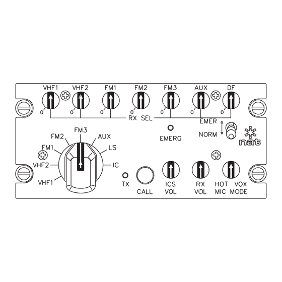
N335 Series Audio Controller SM46 Installation and Operation Manual N335-201 N335-202 NAV1 NAV2 DME1 DME2 VHF1 VHF2 VHF1 VHF2 RX SEL RX SEL EMER NORM VHF2 VHF2 VHF1 VHF1 CALL MIC MODE MIC MODE The N335-201 and N335-202 are identical to the N335-001 and N335-002 except that instead of annunciator LEDs, they have deadfront text annunciators. -
Page 54: Transmit Selection
N335 Series Audio Controller SM46 Installation and Operation Manual 3.3.3 Transmit Selection The transmit selection control is an edge lighted plastic rotary control used to select the microphone for radio transmit, loudspeaker (LS) or Intercom (IC) operation. The TX function is ‘shared’ by the two headsets that can be connected to the N335. -
Page 55: Call
N335 Series Audio Controller SM46 Installation and Operation Manual 3.3.5 CALL CALL LED (N335-001) CALL Button (N335-002 and -202) (Deadfront text on N335-201) When the N335-002 or -202 user presses the momentary CALL button, the green CALL LED (N335-001) or deadfront text (N335-201) will illuminate to indicate that communication is requested.
Need help?
Do you have a question about the SM46 and is the answer not in the manual?
Questions and answers