Table of Contents
Advertisement
Quick Links
SPECIAL NOTICE
This product is now licensed to Anodyne Electronics Manufacturing (AEM) from Northern
Airborne Technology (NAT). AEM is responsible for all matters related to this product, including
sales, support and repair services.
Please note the transition to convert product manuals and supporting documentation is an
ongoing process and is being addressed on an 'as needed' basis.
All references to NAT product part numbers (and associated images) are equivalent to AEM
product part numbers.
Contact info:
Anodyne Electronics Manufacturing Corp.
#15-1925 Kirschner Road
Kelowna B.C. Canada
V1Y 4N7
Email:
support@aem-corp.com
Toll Free: 1-888-763-1088
Phone: 1-250-763-1088
Fax: 1-250-763-1089
www.aem-corp.com
Advertisement
Table of Contents

Related Manuals for AEM SM19


Summary of Contents for AEM SM19
- Page 1 SPECIAL NOTICE This product is now licensed to Anodyne Electronics Manufacturing (AEM) from Northern Airborne Technology (NAT). AEM is responsible for all matters related to this product, including sales, support and repair services. Please note the transition to convert product manuals and supporting documentation is an ongoing process and is being addressed on an ‘as needed’...
- Page 2 REV 5.00 May 29, 2012 Anodyne Electronics Manufacturing Corp. 15-1925 Kirschner Road Kelowna, BC, Canada. V1Y 4N7 Telephone (250) 763-1088 Facsimile (250) 763-1089 Website: www.aem-corp.com © 2012 Anodyne Electronics Manufacturing Corp. (AEM), All Rights Reserved CONFIDENTIAL AND PROPRIETARY TO ANODYNE ELECTRONICS MANUFACTURING CORP.
- Page 3 © 2012 Anodyne Electronics Manufacturing Corp. (AEM), All Rights Reserved This publication is the property of AEM and is protected by Canadian copyright laws. No part of this document may be reproduced or transmitted in any form or by any means including electronic, mechanical, photocopying, recording, or otherwise, without the prior written permission of AEM.
- Page 4 AMS42/AMS44 Dual Channel Audio Controller SM19 Installation and Operation Manual Prepared By: Checked By: Approved By: Tom Betzelt Tony Pearson Loen Clement Product Support Designer Designer Manager May 29, 2012 Jun 11/12 June 11, 2012 The status of this installation and operation manual is controlled by the revision shown on the title page.
-
Page 5: Table Of Contents
AMS42/AMS44 Dual Channel Audio Controller SM19 Installation and Operation Manual Table of Contents Section Title Page Description Introduction Purpose of Equipment Features 1.3.1 Transmit Features 1.3.2 Receive Features 1.3.3 ICS Features Specifications 1.4.1 Electrical Specifications 1.4.2 Physical Specifications 1.4.3 Environmental Specifications... - Page 6 AMS42/AMS44 Dual Channel Audio Controller SM19 Installation and Operation Manual Section Title Page 3.5.2 Passenger ICS Operation AMS42 – Mode Control 3.6.1 Emergency Operation 3.6.2 Isolation Operation AMS44 – General Operation AMS44 – Audio Alerting Functions AMS44 – Selection of Transmit Functions 3.9.1...
-
Page 7: Description
AMS42/AMS44 Dual Channel Audio Controller SM19 Installation and Operation Manual Section 1.0 Description Introduction This manual contains information on the AMS42 and AMS44 Dual Channel Audio Controllers. Information in this section consists of purpose of equipment, features and specifications. Purpose of Equipment The AMS42 and AMS44 are dual channel audio controllers that provide central control of all aircraft audio. - Page 8 AMS42/AMS44 Dual Channel Audio Controller SM19 Installation and Operation Manual 1.3.1 Transmit Functions Both controllers provide equal transmit capability between left and right sides and support the use of a hand microphone. The hand mic is internally configured for left or right side operation, and is connected directly to the selected radio for use during emergency or equipment failure situations.
-
Page 9: Specifications
AMS42/AMS44 Dual Channel Audio Controller SM19 Installation and Operation Manual Specifications 1.4.1 Electrical Specifications Input Power Typically +22 to +32 Vdc at 250 mA Lighting 160 mA at 28 Vdc ‘Carbon equivalent’ 250 mV into 150Ω min. Microphone Requirement (David Clark M1/DC, M3, M4, M7... -
Page 10: Environmental Specifications
AMS42/AMS44 Dual Channel Audio Controller SM19 Installation and Operation Manual 1.4.3 Environmental Specifications Temperature: -20 C. to +55 C (ambient) -55 C. to + 85 C (survival) Altitude 25,000 feet max Humidity 95% Non-condensing Shock 12 g (any axis) Conforms to DO-160B category ‘P’... -
Page 11: Installation
Verify that all items are present before proceeding and report any shortage immediately to your supplier. 2.2.1 Warranty All Anodyne Electronics Manufacturing Corp. (AEM) products are warranted for 2 years. See the website www.aem-corp.com/warranty for complete details. Continued Airworthiness Maintenance of the AMS42 or AMS44 Dual Channel Audio Controller is ‘on condition’ only. Periodic maintenance of this product is not required. -
Page 12: Cautions
AMS42/AMS44 Dual Channel Audio Controller SM19 Installation and Operation Manual 2.4.2 Cautions In all installations, use shielded cable exactly as shown and ground as indicated. Significant problems may result from not following these guidelines. All audio installations can be seriously degraded by incorrect wiring and shielding, and may result in abnormal cross-talk, hum and ground-loop noise. -
Page 13: Top Panel Adjustments
AMS42/AMS44 Dual Channel Audio Controller SM19 Installation and Operation Manual 2.5.1 Top Panel Adjustments 2.5.1.1 Receive Selection Switches AMS42: The receive selection switches for the navaids are two banks of rocker switches accessible through the top cover. The right side of the controller responds to the switches labeled RIGHT USER RX and the left side responds to the switches labeled LEFT USER RX. -
Page 14: Right Side Adjustments
AMS42/AMS44 Dual Channel Audio Controller SM19 Installation and Operation Manual 2.5.1.2 DIR AUDIO Inputs These are coupled directly to either the Right User (P) or Left User (C) of the controller by jumpers accessible through the top cover and labeled DIR AUDIO #1 or DIR AUDIO #2. -
Page 15: Left Side Adjustments
AMS42/AMS44 Dual Channel Audio Controller SM19 Installation and Operation Manual 2.5.2.3 ICS GAIN LEVEL This factory preset pot may be covered by an adhesive disc to prevent field adjustment. Under normal operation this pot does not need to be adjusted. Any adjustment should be carried out by qualified personnel only! 2.5.2.4... -
Page 16: Post-Installation Checks
AMS42/AMS44 Dual Channel Audio Controller SM19 Installation and Operation Manual 2.5.4 Post-Installation Checks With the controller disconnected from its mating connector, check P101 pin <17> for +28 Vdc relative to ground, and check P101 pin <34> for continuity to ground (below 0.5 ). -
Page 17: Installation Drawings
AMS42/AMS44 Dual Channel Audio Controller SM19 Installation and Operation Manual D50SL-IKC consists of Quantity Description AEM Part # D-min 50 Socket Housing 20-21-050 MS Crimp Socket 20-26-901 Jack Screw Set 20-27-002 Lock Clip Set 20-27-004 50 Pin Connector Hood 20-29-051... - Page 22 2.00 Nov 10/11 RAS #19 - CHANGED TO AEM LOGO, UPDATED HOLE SCHEDULE. RX-ON RX-ON RX-ON RX-ON AMS42 AMS42 LIVE 1 KEYED KEYED LIVE ICS VOL ICS VOL ICS VOL ICS VOL NORM NORM Confidential and Proprietary to NAT KELOWNA BC CANADA (250)-763-1088 WWW.AEM-CORP.COM...
- Page 23 1.55 [39.4] Tony Pearson Designer Mar 7, 2011...
- Page 28 2.00 17-Jan-12 RAS #38 - CHANGED TO AEM LOGO, UPDATED FORMAT. NAV1 NAV1 NAV2 NAV2 NAV1 NAV1 NAV2 NAV2 AMS44 AMS44 COM1 COM1 COM2 COM2 COM1 COM1 COM2 COM2 LIVE LIVE ICS VOL ICS VOL ICS VOL ICS VOL EMER...
- Page 29 Reviewed/Approved Tony Pearson Designer May 29, 2012 RAS# 82 1.55 [39.4] Tony Pearson Designer Mar 7, 2011...
-
Page 30: Operation
AMS42/AMS44 Dual Channel Audio Controller SM19 Installation and Operation Manual Section 3.0 Operation This section is divided to provide model-specific Operational instructions. Operation Instructions for the AMS42 can be found in Sections 3.1 to 3.6. Operation Instructions for the AMS44 can be found in Sections 3.7 to 3.12. -
Page 31: Ams42 - Selection Of Transmit Functions
AMS42/AMS44 Dual Channel Audio Controller SM19 Installation and Operation Manual AMS42 - Selection of Transmit Functions Left User (Co-pilot) Transmit Right User (Pilot) Transmit Transmit Selector Annunciator Transmit Selector Annunciator 3.3.1 Transmit Selectors The transmit selector controls are six position rotary switches, one on each side of the panel to correspond to the user on that side of the aircraft. -
Page 32: Ams42 - Transceiver Receive Functions
AMS42/AMS44 Dual Channel Audio Controller SM19 Installation and Operation Manual AMS42 - Transceiver Receive Functions 3.4.1 Receive Selection Switches The receive audio is selected by switching any of the RX switches (white switch bats) UP to connect the indicated radio to the headphone bus. The AUX position does not have a separate RX switch and is connected to the headphone bus by rotating the TX selector to the AUX position. -
Page 33: Volume Controls
AMS42/AMS44 Dual Channel Audio Controller SM19 Installation and Operation Manual 3.4.3 Volume Controls The controller features individual master RX and ICS VOL controls on both the left and right sides of the unit, which can be adjusted to suit the specific user's requirements. -
Page 34: Ics Modes Of Operation
PTT cord, or the controller is set for VOX operation. Passenger and copilot (observer) operations can be maximized by using PTT type cord assemblies designed for use with AEM audio controllers. CAUTION: Ensure that all PTT type cord assemblies have properly shielded mic and phone wiring, or ‘crosstalk’... -
Page 35: Ams42 - Mode Control
AMS42/AMS44 Dual Channel Audio Controller SM19 Installation and Operation Manual AMS42 - Mode Control The Mode Control switch is a three-position, locking toggle switch that is used to select between ISO, EMER OPER, and NORM. It is identified with a red cap. -
Page 36: Ams44 - General Operation
AMS42/AMS44 Dual Channel Audio Controller SM19 Installation and Operation Manual AMS44 - General Operation The AMS44 provides one central controller for all the aircraft audio, allowing selection of transmit and receive audio, LIVE, PTT (Keyed), or VOX intercom, interface for an additional handheld transmit microphone (hand mic), and pilot/copilot isolation/ emergency operation. -
Page 37: Ams44 - Selection Of Transmit Functions
AMS42/AMS44 Dual Channel Audio Controller SM19 Installation and Operation Manual AMS44 - Selection of Transmit Functions Left User (Co-pilot) Transmit Right User (Pilot) Transmit Transmit Selector Annunciator Transmit Selector Annunciator 3.9.1 Transmit Selectors The transmit selector controls are six position rotary switches, one on each side of the panel to correspond to the user on that side of the aircraft. -
Page 38: Hand Microphone
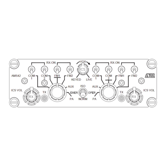
AMS42/AMS44 Dual Channel Audio Controller SM19 Installation and Operation Manual 3.9.1.3 TX Selector Example In the figure that follows, the positions of the rotary selector switches indicate that the left and right sides of the controller are set for transmit operation on the AUX FM transceiver. -
Page 39: Transceiver Selection Examples
AMS42/AMS44 Dual Channel Audio Controller SM19 Installation and Operation Manual 3.10.2 Transceiver Selection Examples In the figure below, the right TX selector is set for transmit and receive operation on the AUX FM. The Receive function switches are also selected so the right side can monitor COM1 and FM2 transceivers as well as NAV1 and DME navaids. -
Page 40: Passenger Receive Audio Selection
AMS42/AMS44 Dual Channel Audio Controller SM19 Installation and Operation Manual 3.10.3.1 RX Volume Control The RX knobs are the smaller, topmost controls of the dual concentric volume control assemblies. The RX VOL controls provide adjustment of the RX audio selected by the controller from 10% to full. As in... -
Page 41: Ics Modes Of Operation
PTT cord, or the controller is set for VOX operation. Passenger and copilot (observer) operations can be maximized by using PTT type cord assemblies designed for use with AEM audio controllers. CAUTION: Ensure that all PTT type cord assemblies have properly shielded mic and phone wiring, or ‘crosstalk’... -
Page 42: Ams44 - Mode Control
AMS42/AMS44 Dual Channel Audio Controller SM19 Installation and Operation Manual 3.12 AMS44 - Mode Control Mode Control Switch The Mode Control switch is a three-position, locking toggle switch that is used to select between ISO, EMER OPER, and NORM. It is identified with a red cap. -
Page 43: Isolation Operation
AMS42/AMS44 Dual Channel Audio Controller SM19 Installation and Operation Manual 3.12.2 Isolation Operation The mode switch can select an ISO function, which prevents the selected user from receiving ICS audio. This is useful when passengers are interfering with critical flight operations (landing, etc.). It can be preselected at installation to isolate the left or right side.
Need help?
Do you have a question about the SM19 and is the answer not in the manual?
Questions and answers