Table of Contents
Advertisement
Available languages
Available languages
Quick Links
READ INSTRUCTIONS CAREFULLY BEFORE ATTEMPTING TO ASSEMBLE OR SERVICE THE LEADING EDGE
CEILING FAN. FAILURE TO COMPLY WITH INSTRUCTIONS COULD RESULT IN PERSONAL INJURY AND/OR
PROPERTY DAMAGE.
RETAIN FOR FUTURE REFERENCE.
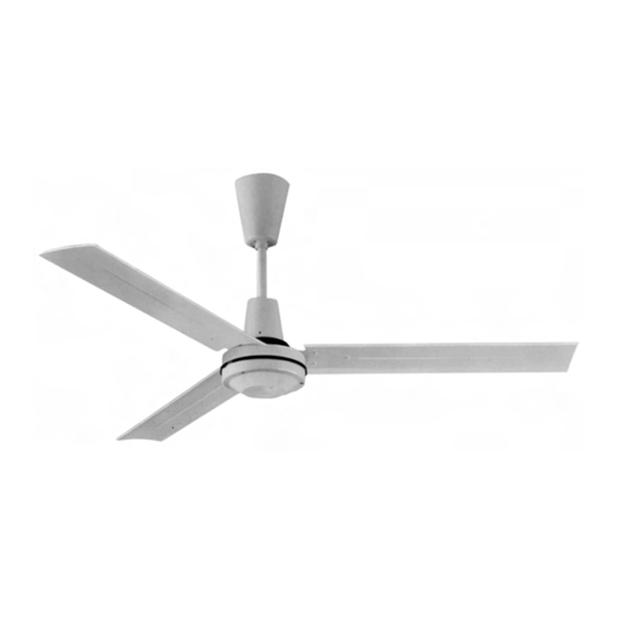
Figure 1
Description
The Leading Edge agricultural ceiling fans are designed
as a dual purpose product. By minimizing temperature
stratification in winter, they can reduce heating costs by
bringing trapped hot air to the floor. The summertime
application provides a gentle downward movement of air
for general air recirculation and evaporative cooling. A
permanent split capacitor motor and permanently
lubricated sealed ball bearings add to the efficiency and
quietness of the fan.
Specifications
Motor
120VAC/60Hz
Blade Size, Dia.
Square foot
Coverage for
Heat Stratification
3,025 sq. ft.
CFM
RPM
AMPS
WATTS
Weight (LBS)
Unpacking
1. Remove fan components from carton carefully.
2. Check for shipping damage.
3. Check for any missing parts against parts list.
ASSEMBLY INSTRUCTIONS & PARTS MANUAL FOR
56" & 60" SPRAY PROOF CEILING FANS
MODELS 5610-1 AND 6010-1
56" & 60" AGRICULTURAL CEILING FANS
MODELS 5611-1 AND 6011-1
56" FAN
60" FAN
120VAC/60Hz
56"
60"
5,000 sq. ft.
25,500
41,000
265
280
1.0
1.40
110
160
24
30
General Safety Information
W A R N I N G : D I S C O N N E C T P O W E R B E F O R E
INSTALLING OR SERVICING THIS EQUIPMENT.
1. Mount 56" fans so that fan blades are 7 feet or higher
above the floor. Mount 60" fans so that blades are 10
feet or higher above the floor.
WARNING: DO NOT USE IN AN EXPLOSIVE
ATMOSPHERE.
2. All electrical wiring should be done by a qualified
electrician in accordance with applicable National
Electrical Code and local electrical codes.
3. Make sure hanger hooks are mounted securely to
structural ceiling members.
4. Do not allow moving blades to come in contact with
any part of the body.
5. Make certain that the ground wire is connected to the
ground terminal and to a suitable electrical ground.
NOTE: When mounted in cathedral ceilings, the blade tip
should be at least 12 inches from the angled roof line to
prevent air "blow-back" causing possible fan sway.
CAUTION: Read and follow instructions carefully.
Failure to comply with instructions could result in
the risk of fire, shock, and injury to persons.
WARNING: TO REDUCE THE RISK OF PERSONAL
INJURY, DO NOT BEND THE BLADE BRACKETS
WHEN INSTALLING THE BRACKETS OR CLEANING
THE FAN. DO NOT INSERT FOREIGN OBJECTS IN
BETWEEN ROTATING FAN BLADES.
Installation
RECOMMENDED MOUNTING HEIGHTS
This fan is pre-assembled with a one foot long down rod
which is suitable for both heat reclamation in the winter
and warm weather cooling in the summer.
WARNING: ALL CEILING FANS SHOULD BE IN-
STALLED BY QUALIFIED PERSONNEL.
CAUTION: 56" fan should not be mounted lower than
7 feet from the floor. 60" fans should not be mount-
ed lower than 10 feet from floor.
Advertisement
Table of Contents

Related Manuals for Leading Edge 5610-1

Summary of Contents for Leading Edge 5610-1
-
Page 1: General Safety Information
MODELS 5610-1 AND 6010-1 56” & 60” AGRICULTURAL CEILING FANS MODELS 5611-1 AND 6011-1 READ INSTRUCTIONS CAREFULLY BEFORE ATTEMPTING TO ASSEMBLE OR SERVICE THE LEADING EDGE CEILING FAN. FAILURE TO COMPLY WITH INSTRUCTIONS COULD RESULT IN PERSONAL INJURY AND/OR PROPERTY DAMAGE. - Page 2 Assembly This fan includes a “secondary support” safety cable fea- CAUTION:Do not allow the permanently installed ture that complies with existing C.S.A. (Canadian lower canopy to touch the revolving motor as Standards Association) requirements and all other damage will occur. Make sure all wires are securely proposed safety regulations for overhead air movement placed to avoid rubbing against the motor.
- Page 3 DRY LOCATION ELECTRICAL WIRE HOOK RUBBER WHITE SAFETY CABLE ROLLER BLACK BLACK WHITE/BLACK BLACK SAFETY CABLE OPTIONAL SOLID STATE REGULATOR Figure 3 MOTOR GRD. GRD. Figure 6 10. Restore power. 11. After completing installation, test run fan in normal operating manner. Inspect for any possible shake or wobble which may be caused by binding as a result of “tight cable”.
-
Page 4: Limited Warranty
Figure 7 - Replacement Parts List Replacement Parts For 56” & 60” Spray Proof 5610-1, 6010-1 and Agricultural 5611-1, 6011-1 REF. PART REF. PART DESCRIPTION DESCRIPTION “J” hook mounting bolt assembly 2100069A Condensation drain plug 3100045A Wood screw hook 2100070A 10-24 x 3/8”... - Page 5 MODELOS 5611-1 y 6011-1 LEA CUIDADOSAMENTE LAS INSTRUCCIONES ANTES DE INTENTAR ENSAMBLAR O SUMINISTRAR SERVICIO DE MANTENIMIENTO AL VENTILADOR DE TECHO LEADING EDGE. NO CUMPLIR LAS INSTRUCCIONES PODRÍA RESUL- TAR EN LESIONES PERSONALES Y/O DAÑO A LA PROPIEDAD. GUARDE PARA FUTURA CONSULTA.
- Page 6 Ensamblaje PRECAUCIÓN: No permita que la cubierta inferior instalada permanentemente haga contacto con el motor girando ya que Este ventilador incluye una característica de cable de seguridad de se producirán daños. Verifique que todos los cables eléctricos “soporte secundario” que cumple con los requerimientos existentes están colocados de manera segura para evitar rozamiento de la Asociación Canadiense de Normas (C.S.A.) y todas las contra el motor.
-
Page 7: Cable Eléctrico
LUGAR SECO CABLE ELÉCTRICO GANCHO RODILLO DE CABLE DE CAUCHO BLANCO SEGURIDAD NEGRO NEGRO BLANCO/NEGRO NEGRO CABLE DE SEGURIDAD REGULADOR DEL TIPO DE ESTADO Figura 3 SÓLIDO, OPCIONAL MOTOR TIERRA TIERRA Figura 6 10. Restaure la energía. 11. Después de terminar la instalación, pruebe la operación del ven- tilador en el modo de operación normal. -
Page 8: Garantia Limitada
Figura 7 - Lista de piezas de repuesto Piezas de repuesto para 56” y 60”, a Prueba de Rociado 5610-1, 6010-1; y Agrícola 5611-1, 6011-1 REF. REF. DESCRIPCIÓN PIEZA NO. CANT. DESCRIPCIÓN PIEZA NO. CANT. 2100069A Tapón de drenaje de condensación 3100045A Perno de montaje tipo gancho en “J”... - Page 9 MODÈLES 5611-1 ET 6011-1 LISEZ SOIGNEUSEMENT CES INSTRUCTIONS AVANT D’ESSAYER D’ASSEMBLER OU D’INTERVENIR SUR CE VENTI- LATEUR DE PLAFOND LEADING EDGE. NE PAS TENIR COMPTE DES INSTRUCTIONS PEUT ENTRAÎNER DES BLESSURES CORPORELLES ET/OU DES DÉGÂTS MATÉRIELS. À CONSERVER COMME RÉFÉRENCE FUTURE.
- Page 10 Montage ATTENTION : Ne laissez pas le chapeau inférieur installé en permanence toucher le moteur tournant car il y aurait des Ce ventilateur comporte un câble de sécurité pour un soutien de dommages. Assurez-vous que tous les fils sont bien disposés secours qui répond aux exigences en vigueur de la CSA pour éviter leur frottement contre le moteur.
- Page 11 ENDROIT SEC FILS ÉLECTRIQUES CROCHET CYLINDRE CÂBLE DE SÉCURITÉ CAOUTCHOUC BLANC NOIR NOIR BLANC/NOIR NOIR CÂBLE DE SÉCURITÉ RÉGULATEUR OPTIONNEL Figure 3 À SEMI-CON- DUCTEUR MOTEUR TERRE TERRE Figure 6 10. Remettez sous tension. 11. À la fin de l’installation, faites tourner le ventilateur en fonction- nement normal.
-
Page 12: Garantie Limitée
Figure 7 – Liste des pièces de rechange Pièces de rechange pour unités 56” et 60” étanches à l’aspersion 5610-1, 6010-1 et pour l’agriculture 5611-1, 6011-1 N° N° DESCRIPTION N° PIÈCE QTÉ N° PIÈCE N° PIÈCE QTÉ RÉF. RÉF. Ensemble de crochet en J avec boulon...
Need help?
Do you have a question about the 5610-1 and is the answer not in the manual?
Questions and answers