Table of Contents
Advertisement
Advertisement
Table of Contents

Related Manuals for Kubota BX25DLB-AU


Summary of Contents for Kubota BX25DLB-AU
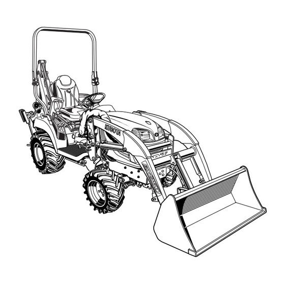
- Page 1 OPERATOR'S MANUAL MODELS BX25DLB-AU LA240A LA240A AU-SG BT602 · · · 1HNAAAEAP0160 1HNAAAEAP0160 AR. F. 1-1. -. K Code No. K2792-7125-1 READ AND SAVE THIS MANUAL PRINTED IN U.S.A. © KUBOTA Corporation 2013...
-
Page 3: Universal Symbols
UNIVERSAL SYMBOLS As a guide to the operation of your tractor, various universal symbols have been utilized on the instruments and controls. The symbols are shown below with an indication of their meaning. 3-Point Lowering Speed Control Safety Alert Symbol Remote Cylinder-Retract Diesel Fuel Remote Cylinder-Extend... -
Page 4: Safety First
FOREWORD You are now the proud owner of a KUBOTA Tractor. This tractor is a product of KUBOTA quality engineering and manufacturing. It is made of fine materials and under a rigid quality control system. It will give you long, satisfactory service. To obtain the best use of your tractor, please read this manual carefully. -
Page 5: Table Of Contents
CONTENTS SAFE OPERATION .................... TRACTOR........................ 1 LOADER ........................7 BACKHOE........................ 9 SERVICING ......................... 1 SPECIFICATIONS OF THE TRACTOR ..............3 SPECIFICATION TABLE ..................3 TRAVELING SPEEDS ..................... 4 SPECIFICATIONS OF THE LOADER................. 5 LOADER SPECIFICATIONS ................... 5 BUCKET SPECIFICATIONS..................5 DIMENSIONAL SPECIFICATIONS ................. - Page 6 CONTENTS Cold Weather Starting ....................26 Block Heater (Option) ..................... 26 STOPPING THE ENGINE..................26 WARMING UP ....................... 27 Warm-up and Transmission Oil in the Low Temperature Range........27 JUMP STARTING ....................27 OPERATING THE TRACTOR ................... 28 OPERATING NEW TRACTOR ................28 Do not Operate the Tractor at Full Speed for the First 50 Hours........
- Page 7 CONTENTS PTO Select Lever ......................43 PTO Clutch Lever ......................44 PTO Shaft Cover and Shaft Cap ..................44 Stationary PTO ....................... 44 PTO Drive Shaft......................45 3-POINT HITCH & DRAWBAR.................. 46 3-POINT HITCH ..................... 47 Attaching and detaching implements................47 Lifting Rod (Right)......................
- Page 8 CONTENTS SPILL GUARD (SPILL GUARD MODEL ONLY)............ 64 Adjustment of spill guard link ..................64 ATTACHING ATTACHMENTS ................65 DETACHING ATTACHMENTS ................67 DISMOUNTING THE LOADER................67 ATTACHMENTS ....................67 Bucket..........................67 Pallet fork........................67 ASSEMBLE PALLET FORK .................. 68 OPERATING THE BACKHOE...................
- Page 9 CONTENTS Checking Wheel Bolt Torque ..................84 EVERY 100 HOURS ....................84 Battery ..........................84 Cleaning Air Cleaner Element ..................86 Checking Fuel Lines and Fuel Filter ................86 Adjusting Fan belt Tension ..................... 87 Adjusting HST Neutral Spring (for Speed Control Pedal) ..........87 Adjusting Brake Pedal ....................
- Page 10 CONTENTS MAINTENANCE OF THE BACKHOE..............100 DAILY CHECKS....................100 LUBRICATION ..................... 101 BUCKET SERVICE....................101 Changing the Backhoe Bucket ..................101 Changing the Bucket Teeth ..................101 General torque specification ..................102 STORAGE OF THE TRACTOR................103 TRACTOR STORAGE ..................103 REMOVING THE TRACTOR FROM STORAGE..........
-
Page 11: Safe Operation
Read and understand this manual carefully before C CAB, ROPS operating the tractor. 1. KUBOTA recommends the use of a CAB or Roll Over Protective Structures (ROPS) and seat belt in almost All operators, no matter how much experience they may all applications. - Page 12 SAFE OPERATION C Working 1. Pull only from the hitch. Never hitch to axle housing or any other point except hitch; such arrangements will increase the risk of serious personal injury or death due to a tractor upset. (1) ROPS (2) Seat belt 2.
-
Page 13: Parking The Tractor
SAFE OPERATION 6. Never allow children to play on the machine or on the 11. Set the implement lowering speed knob in the "LOCK" implement. position to hold the implement in the raised position. 7. Use extra caution when backing up. Look behind and down to make sure area is clear before moving. - Page 14 SAFE OPERATION 4. When parking your machine if at all possible park on a firm, flat and level surface; if not, park across a slope. 5. USING 3-POINT HITCH Set the parking brake(s), lower the implements to the ground, remove the key from the ignition and lock the 1.
- Page 15 SAFE OPERATION 10. Do not attempt to mount a tire on a rim. This should be done by a qualified person with the proper equipment. 6. SERVICING THE TRACTOR 11. Always maintain the correct tire pressure. Do not inflate tires above the recommended pressure shown Before servicing the tractor, park it on a firm, flat and level in the operator's manual.
- Page 16 17. Waste products such as used oil, fuel, hydraulic fluid, and batteries, can harm the environment, people, pets and wildlife. Please dispose properly. See your local Recycling Center or KUBOTA Dealer to learn how to recycle or get rid of waste products.
- Page 17 3. For your safety, a ROPS with a seat belt is strongly operating loader and tractor. recommended by KUBOTA in almost all applications. 5. Do not walk or work under a raised loader bucket or If your tractor has a foldable ROPS, fold it down only...
- Page 18 SAFE OPERATION 18. Be extra careful when operating the tractor on a slope, always operate up and down, never across the slope. Do not operate on steep slopes or unstable surfaces. 19. When operating another implement on a hillside, be sure to remove the loader to reduce the risk of rollover.
- Page 19 SAFE OPERATION BACKHOE Most backhoe equipment accidents can be avoided by following simple safety precautions. These safety precautions, if followed at all times, will help you operate your backhoe safely. BEFORE OPERATING BACKHOE 3. DRIVING THE TRACTOR ON THE ROAD 1.
- Page 20 SAFE OPERATION...
- Page 21 SAFE OPERATION...
- Page 22 SAFE OPERATION...
- Page 23 SAFE OPERATION...
- Page 24 SAFE OPERATION...
- Page 25 SAFE OPERATION...
- Page 26 SAFE OPERATION...
- Page 27 2. Clean danger, warning and caution labels with soap and water, dry with a soft cloth. 3. Replace damaged or missing danger, warning and caution labels with new labels from your local KUBOTA Dealer. 4. If a component with danger, warning and caution label(s) affixed is replaced with new part, make sure new label(s) is (are) attached in the same location(s) as the replaced component.
-
Page 29: Tractor
KUBOTA Dealer. For service, contact the KUBOTA Dealership from which you purchased your tractor or your local KUBOTA Dealer. When in need of parts, be prepared to give your dealer the tractor, engine, loader and backhoe serial number. - Page 30 SERVICING (1) ROPS identification plate (ROPS serial No.) (1) Loader serial number A The loader serial number label (1) is attached to the inside of the boom.
-
Page 31: Specifications Of The Tractor
SPECIFICATIONS OF THE TRACTOR SPECIFICATIONS OF THE TRACTOR SPECIFICATION TABLE Model BX25DLB-AU PTO power *1 kW (HP) 13.2 (17.7) Maker KUBOTA Model D902 Type Indirect injection, vertical, water-cooled, 4-cycle diesel Number of cylinders Bore and stroke 72 x 73.6 Total displacement... -
Page 32: Traveling Speeds
SAE 1-3/8, 6 splines Rear PTO Revolution 1 speed (540 rpm at 3142 engine rpm) USA No.5 (KUBOTA 10-tooth) involute spline MID-PTO Revolution 1 speed (2500 rpm at 3043 engine rpm) The company reserve the right to change the specifications without notice. -
Page 33: Specifications Of The Loader
SPECIFICATIONS OF THE LOADER SPECIFICATIONS OF THE LOADER LOADER SPECIFICATIONS LOADER MODEL LA240A LA240A AU-SG TRACTOR MODEL BX25DLB-AU BORE mm BOOM CYLINDER STROKE mm BORE mm BUCKET CYLINDER STROKE mm 1 Detent Float Position, 2 Stage Bucket Dump, CONTROL VALVE... -
Page 34: Dimensional Specifications
SPECIFICATIONS OF THE LOADER DIMENSIONAL SPECIFICATIONS LOADER MODEL LA240A / LA240A AU-SG TRACTOR MODEL BX25DLB-AU A MAX. LIFT HEIGHT (TO BUCKET PIVOT PIN) 1810 B MAX. LIFT HEIGHT UNDER LEVEL BUCKET 1680 C CLEARANCE WITH BUCKET DUMPED 1330 REACH AT MAX. LIFT HEIGHT (DUMPING REACH) E MAX. -
Page 35: Loader
SPECIFICATIONS OF THE LOADER OPERATIONAL SPECIFICATIONS LOADER MODEL LA240A LA240A AU-SG TRACTOR MODEL BX25DLB-AU RATED OPERATING LOAD (500 mm FORWARD, MAX. HEIGHT) kg BUCKET ROLL-BACK FORCE AT MAX. HEIGHT 4750 BUCKET ROLL-BACK FORCE AT 1500mm HEIGHT 5600 BUCKET ROLL-BACK FORCE AT GROUND LEVEL... -
Page 36: Loader Terminology
SPECIFICATIONS OF THE LOADER LOADER TERMINOLOGY (1) Loader control lever (6) Boom (2) Side frame (7) Bucket cylinder (3) Mounting pin (8) Bucket (4) Main frame (9) Lock lever (5) Boom cylinder (10) Spill guard valve (Spill guard model only) -
Page 37: Backhoe
Stabilizer spread-operating 1862 mm Angle of departure per SAE J1234 (A3) 20.1 deg. Leveling angle 11 deg. Swing arc 140 deg. A The specifications are taken with KUBOTA BX25DLB tractor. (Tire size : Front 18 X 8.5-10, Rear 26 X 12.00-12) -
Page 38: Specifications
SPECIFICATIONS OF THE BACKHOE BSpecifications Digging force (Per SAE J49) With bucket cylinder 8610 N With dipperstick cylinder 5209 N Cycle Time (seconds) Boom cylinder, extend Boom cylinder, retract Swing cylinder, from 90 degrees to center Dipperstick cylinder, extend Dipperstick cylinder, retract Bucket cylinder, extend Bucket cylinder, retract Stabilizer cylinder, max. - Page 39 SPECIFICATIONS OF THE BACKHOE Hydraulic cylinders Boom Dipperstick Bucket Stabilizer Swing Rod diameter Cylinder bore Bucket Sizes SAE truck SAE Heaped Number Width Weight Capacity Capacity Teeth Trenching 8" 20.3 0.009 0.011 Trenching 12" 30.5 0.014 0.020...
-
Page 40: Lift Capacity (Per Sae J31)
SPECIFICATIONS OF THE BACKHOE BLift Capacity (Per SAE J31) Lift capacities shown are 87% of maximum lift force, according to SAE definition. -
Page 41: Backhoe Terminology
SPECIFICATIONS OF THE BACKHOE BACKHOE TERMINOLOGY (1) Backhoe bucket (2) Bucket teeth (3) Bucket link (4) Bucket cylinder (5) Dipperstick (6) Dipperstick cylinder (7) Boom (8) Boom cylinder (9) Swing frame (10) Main frame (11) Swing cylinder (12) Stabilizer (13) Stabilizer pad (14) Stabilizer cylinder (15) Joystick control (16) Stabilizer control... -
Page 42: Implement Limitations
Use with implements which are not sold or approved by KUBOTA and which exceed the maximum specifications listed below, or which are otherwise unfit for use with the KUBOTA Tractor may result in malfunctions or failures of the tractor, damage to other property and injury to the operator or others. [Any malfunctions or failures of the tractor resulting from use with improper implements are not covered by the warranty.]... - Page 43 Max. weight 1100 *1 KUBOTA provides BT602 Backhoe for BX25DLB-AU. No other Backhoe installed by 3-point hitch is permitted for BX25DLB-AU. *2 KUBOTA provides LA240A, LA240A AU-SG Front-end Loader for BX25DLB-AU. *3 The value contains the weight of KUBOTA standard bucket.
-
Page 44: Instrument Panel And Controls
INSTRUMENT PANEL AND CONTROLS INSTRUMENT PANEL AND CONTROLS B Instrument Panel, Switches and Hand Controls ILLUSTRATED CONTENTS (1) Easy Checker(TM)..........24,37 (2) Tachometer............(3) Hazard light switch..........(4) Turn signal light switch.......... (5) Head light switch........... (6) Fuel gauge............(7) Coolant temperature gauge........(8) Hourmeter............ - Page 45 INSTRUMENT PANEL AND CONTROLS B Foot and Hand Controls ILLUSTRATED CONTENTS (1) Brake pedal................. 24,32,34,38 (2) Parking brake lock pedal............. 24,32,34,38 (3) 3-Point hitch lowering speed knob........(4) Cutting height control dial............ (5) PTO select lever..............(6) PTO clutch lever..............24,44 (7) Differential lock pedal............
-
Page 46: Pre-Operation Check Of The Tractor
PRE-OPERATION CHECK OF THE TRACTOR PRE-OPERATION CHECK OF THE TRACTOR DAILY CHECK To prevent trouble from occurring, it is important to know the condition of the tractor well. Check it before starting. To avoid personal injury: A Be sure to check and service the tractor on a level surface with the engine shut off and the parking brake "ON"... -
Page 47: Pre-Operation Check Of The Loader
PRE-OPERATION CHECK OF THE LOADER PRE-OPERATION CHECK OF THE LOADER LUBRICATION C Liquid ballast in rear tires Water and calcium chloride solution provides a safe and Lubricate all grease fittings with SAE multipurpose economical ballast. Used properly, it will not damage tires, grease. - Page 48 Rated operation load (ROL) 220 kg *Be sure to install the counter weight approved by KUBOTA. The use of a counter weight significantly reduces the front axle and tire load during loader operation. It also increases the fore/aft stability of the tractor/loader by shifting weight from the front axle to the rear axle.
-
Page 49: Rated Operating Load (Spill Guard Model Only)
A Do not operate the loader without counter weight. A Do not exceed 10 km/h when travelling with load. A Use only tires approved by Kubota for loader use. A ROL is calculated with standard bucket. Optional attachments (4IN1 bucket etc.) will reduce ROL. -
Page 50: Tire Inflation
PRE-OPERATION CHECK OF THE LOADER TIRE INFLATION Insure that the tractor tires are properly inflated. See "TIRES, WHEELS AND BALLAST" section. TEST OPERATION To avoid serious personal injury: A Keep engine speed at low idle during the test operation. A Escaping hydraulic fluid under pressure can have sufficient force to penetrate skin, causing serious personal injury. -
Page 51: Pre-Operation Check Of The Backhoe
A Never remove loader to ensure tractor stability OPERATOR'S SEAT at all times. Operator's seat for the BX25DLB-AU tractor can be used to operate loader and backhoe. See "OPERATING THE A Do not add liquid ballast or any other weights to the TRACTOR"... -
Page 52: Operating The Engine
OPERATING THE ENGINE OPERATING THE ENGINE A It is recommended that the operator practice engaging and disengaging the parking brake on a flat surface To avoid personal injury: without the engine running before operating the tractor A Read "SAFE OPERATION" in the front of this for the first time. - Page 53 OPERATING THE ENGINE 4. Lock loader control lever 6. Set the throttle lever to about 1/2 way. "NEUTRAL" position. (1) Hand throttle lever "INCREASE" (1) Loader control lever (A) "LOCK" "DECREASE" (2) Lock lever 7. Insert the key into the key switch and turn it "ON".
-
Page 54: Cold Weather Starting
(See "DAILY CHECK" in "PERIODIC SERVICE OF THE TRACTOR" section.) A If key does not stop the engine, consult your local KUBOTA Dealer. 8. Turn the key to "PREHEAT" position and hold it for about 2 to 3 seconds. For the appropriate preheating time, refer to the table... -
Page 55: Warming Up
OPERATING THE ENGINE WARMING UP When jump starting engine, follow the instructions below to safely start the engine. 1. Bring helper vehicle with a battery of the same voltage as disabled tractor within easy cable reach. "THE To avoid personal injury: VEHICLES MUST NOT TOUCH". -
Page 56: Operating The Tractor
A On rough roads, slow down to suitable speeds. If interference occurs, contact your KUBOTA Do not operate the tractor at fast speed. Dealer. The above precautions are not limited only to new tractors, but to all tractors. But it should be especially BTo Fold the ROPS observed in the case of new tractors. -
Page 57: To Raise The Rops To Upright Position
OPERATING THE TRACTOR 2. Remove both set pins. 4. Align set pin holes and insert both set pins and secure them with the hair pins. To avoid personal injury: A Make sure that both set pins are properly installed and secured with the hair pins. (1) Set pins (2) Hair pins 3. -
Page 58: Adjustment Of Foldable Rops
OPERATING THE TRACTOR 3. Align set pin holes, insert both set pins. Secure them with the hair pins. BAdjustment of Foldable ROPS A Adjust free fall of the ROPS upper frame regularly. A If you feel less friction in folding the ROPS, tighten the nut (1) until you feel the right friction in the movement. -
Page 59: Starting
OPERATING THE TRACTOR STARTING BOperator's Seat 1. Adjust the operator's position and engage the seat belt. To avoid personal injury: A Make adjustments to the seat only while the tractor is stopped. A The seat and suspension should be adjusted to A Make sure that the seat is completely secured ensure that the controls are comfortably at hand for the after each adjustment. -
Page 60: Seat Belt
OPERATING THE TRACTOR BSeat Belt BTurn Signal Light Switch To indicate a right turn, turn the switch clockwise. To indicate a left turn, turn the switch counter-clockwise. When the left or right turn signal is activated in To avoid personal injury: combination with the hazard lights, the indicated turning A Always use the seat belt when the ROPS is light will flash and the other will stay on. -
Page 61: Range Gear Shift Lever (Hi-Lo)
OPERATING THE TRACTOR 6. Select the Travel Speed. BRange Gear Shift Lever (Hi-Lo) The range gear shift can only be shifted when tractor is completely stopped. To avoid personal injury: A Make sure the range shift lever is fully engaged into "H"... -
Page 62: Front Wheel Drive Lever
OPERATING THE TRACTOR C Front wheel drive is effective for the following jobs: BFront Wheel Drive Lever 1. When greater pulling force is needed, such as working in a wet field, when pulling a trailer, or when working with a front-end loader. To avoid personal injury: 2. -
Page 63: Speed Control Pedal
OPERATING THE TRACTOR 9. Depress the Speed Control Pedal. BSpeed Set Device The Speed Set Device is designed for tractor operating efficiency and operator's comfort. This device will provide BSpeed Control Pedal a constant forward operating speed by mechanically holding the speed control pedal at a selected position. C To engage Speed Set Device To avoid personal injury: 1. -
Page 64: Stopping
OPERATING THE TRACTOR STOPPING BStopping 1. Slow the engine down. 2. Step on the brake pedal. 3. After the tractor has stopped, disengage the PTO, lower the implement to the ground, shift the transmission to "NEUTRAL" and set the parking brake. -
Page 65: Easy Checker(Tm)
Overheat indication: A For checking and servicing of your tractor, consult 1. When the coolant temperature stays at 125 C for 5 your local KUBOTA Dealer for instructions. seconds, the indicator on the Easy Checker(TM) comes on. BFuel Gauge 2. -
Page 66: Hourmeter/Tachometer
OPERATING THE TRACTOR PARKING BParking To avoid personal injury: BEFORE DISMOUNTING TRACTOR A ALWAYS SET PARKING BRAKE AND LOWER ALL IMPLEMENTS TO THE GROUND. Leaving transmission in gear with the engine stopped will not prevent the tractor from accidental rolling. A STOP THE ENGINE AND REMOVE THE KEY. -
Page 67: Accessory
OPERATING THE TRACTOR ACCESSORY OPERATING TECHNIQUES B12V Electric Outlet BDifferential Lock An auxiliary light or other devices may be connected to this connector. To avoid personal injury due to loss of steering control: A Do not connect a light or other device that draws more A Do not operate the tractor at high speed with than 120 watts to this connector, or the battery may differential lock engaged. -
Page 68: Operating The Tractor On A Road
OPERATING THE TRACTOR BOperating the Tractor on a Road BTransport the Tractor Safely 1. The tractor, if damaged, must be carried on a truck. Secure the tractor tightly with ropes. 2. Follow the instruction below when towing the tractor: To avoid personal injury: Otherwise, the tractor’s powertrain may get damaged. -
Page 69: Reversing The Seat
OPERATING THE TRACTOR REVERSING THE SEAT 3. Raise the seat until the seat pin comes in to the detent notch (see illustration). (A) "TRACTOR DRIVING POSITION" (B) "BACKHOE POSITION" The seat is reversible for backhoe operation. Follow the procedure below to turn the seat around. 1. - Page 70 OPERATING THE TRACTOR 5. Push the seat backward, then the seat pin will come out from detent notch. Push the seat down until the lever is locked at the backhoe position. A If the seat pin does not come out from the detent notch, apply grease in the notch.
-
Page 71: Pto
C Mid-PTO adjusting, cleaning driven The Mid-PTO is available for KUBOTA approved equipment. implements. BPTO Select Lever The tractor has a 540 rpm rear PTO speed and a 2500 rpm mid-PTO speed. (1) Mid-PTO (1) PTO select lever... -
Page 72: Pto Clutch Lever
BPTO Clutch Lever 1. The PTO clutch lever engages or disengages the PTO clutch which gives the PTO independent control. 2. Shift the lever to "ON" to engage the PTO clutch. Shift the lever to "OFF" to disengage the PTO clutch. (1) PTO shaft cover (A) "NORMAL POSITION"... -
Page 73: Pto Drive Shaft
BPTO Drive Shaft (1) Inner and outer sliding profile tubes (2) Journal cross assy (3) Fitting yoke (4) Safety guard (In, Out) (5) Chain 1. When using a PTO drive shaft, read the operator's manual of the implement before operating the implement. -
Page 74: 3-Point Hitch & Drawbar
3-POINT HITCH & DRAWBAR 3-POINT HITCH & DRAWBAR (1) Top link Use holder plate to hold lower link higher while mowing (2) Lifting rod (Left) with mid-mount mower only over uneven terrain. (3) Check chains (4) Turnbuckle (5) Lower link (6) Top link holder (7) Lifting rod (Right) (8) Drawbar... -
Page 75: 3-Point Hitch
3-POINT HITCH & DRAWBAR 3-POINT HITCH 2. The proper length of the top link varies according to the type of implement being used. BAttaching and detaching implements A When not using the top link, make it the shortest length and fix it to the top link holder. To avoid personal injury: A Be sure to stop the engine and remove the key. -
Page 76: Removing The 3-Point Hitch
3-POINT HITCH & DRAWBAR 3. Remove the hair pin and stopper pin. Then remove the check chain plate and lower links. BRemoving the 3-Point Hitch When installing the backhoe, remove the 3-point hitch. BInstalling the 3-Point Hitch 1. Remove the lynch pin and the top link pin. Then 1. -
Page 77: Hydraulic Unit
3-point Unless corrected the unit will be damaged. hitch mounted implement. Contact your KUBOTA Dealer for adjustment. To lower implement, move the hydraulic control lever forward; to raise it, move the hydraulic control lever B3-point Hitch Lowering Speed rearward. -
Page 78: Auxiliary Hydraulics
HYDRAULIC UNIT AUXILIARY HYDRAULICS BHydraulic Outlet On the tractor hydraulic outlet is provided. It can be used with the BT602 Backhoe. When mounting the backhoe. To avoid serious personal injury: 1. Disconnect the coupler. A Escaping hydraulic fluid under pressure can have sufficient force to penetrate skin, causing serious personal injury. -
Page 79: Installing Mower
HYDRAULIC UNIT INSTALLING MOWER 5. Place the protective cap on the coupler of the backhoe inlet hose, the coupler of the outlet hose, and power Do not attach nor operate the mower with the backhoe still beyond hose. in place. 6. -
Page 80: Mower Lift Linkage System
HYDRAULIC UNIT MOWER LIFT LINKAGE SYSTEM BCutting Height Control Dial (1) Cutting height control dial (2) Hydraulic control lever (1) Mower rear link When mounting the Mid-mount mower, turn the cutting height control dial to the desired height. For further details, refer to the operator's manual of ROTARY MOWER RCK60B-23BX, RCK54P-23BX and RCK54-23BX. -
Page 81: Hydraulic Control Unit Use Reference Chart
HYDRAULIC UNIT BHydraulic Control Unit Use Reference Chart In order to handle the hydraulics properly, the operator must be familiar with the following. Though this information may not be applicable to all types of implements and soil conditions, it is useful for general conditions. Implement Remarks Soil condition... -
Page 82: Tires, Wheels And Ballast
BFront Wheels Front tread can not be adjusted. A Do not use tires other than those approved by KUBOTA. A Do not turn front discs to obtain wider tread. A When you intend to mount different size of tires from... -
Page 83: Rear Wheels
TIRES, WHEELS AND BALLAST A Use the tapered bolts for wheels with beveled or tapered holes. To avoid personal injury: A Before jacking up the tractor, park it on a firm and level ground and chock the rear wheels. A Fix the front axle to keep it from swinging. A Select jacks that withstand the machine weight and set them up as shown below. -
Page 84: Ballast
TIRES, WHEELS AND BALLAST BALLAST C Liquid ballast in rear tires Water and calcium chloride solution provides a safe and economical ballast. Used properly, it will not damage tires, tubes or rims. The addition of calcium chloride is To avoid personal injury: recommended to prevent the water from freezing. - Page 85 Rated operation load (ROL) 220 kg *Be sure to install the counter weight approved by KUBOTA. The use of a counter weight significantly reduces the front axle and tire load during loader operation. It also increases the fore/aft stability of the tractor/loader by shifting weight from the front axle to the rear axle.
-
Page 86: Operating The Loader
OPERATING THE LOADER OPERATING THE LOADER The loader should be operated with the tractor engine The rollback and lifting of the bucket will increase speed depending on the application and the operator's efficiency because a level bucket throughout the lifting level of experience. -
Page 87: Carrying The Load
OPERATING THE LOADER CARRYING THE LOAD LOWERING THE BUCKET Position the bucket just below the level of the tractor hood After the bucket is dumped, back away from the vehicle for maximum stability and visibility, whether the bucket is while lowering and rolling back the bucket. loaded or empty. -
Page 88: Loading From A Bank
OPERATING THE LOADER LOADING FROM A BANK Another method for large dirt piles is to build a ramp to approach the pile. Choose a forward gear that provides a safe ground speed and power for loading. It is important to keep the bucket level when approaching a bank or pile. -
Page 89: Loading Low Trucks Or Spreaders From A Pile
OPERATING THE LOADER LOADING LOW TRUCKS OR SPREADERS FROM A PILE A Do not use the bucket in the dumped position for bulldozing. As shown above, this method will impose severe shock loads on the dump-linkage, the bucket cylinders, and the tractor. Leave dirt in the bucket because dumping on each pass For faster loading, minimize the angle of turn and length wastes time. -
Page 90: Handling Large Heavy Objects
OPERATING THE LOADER HANDLING LARGE HEAVY OBJECTS VALVE LOCK To avoid injury from crushing: To avoid serious personal injury or death: A Do not utilize the valve lock for machine A Handling large, heavy objects maintenance or repair. dangerous due to : A The valve lock is to prevent accidental (A) Danger of rolling the tractor over. -
Page 91: Boom Lock (Spill Guard Model Only)
OPERATING THE LOADER [To Remove the Boom Lock] BBoom Lock (Spill guard model only) 1. Raise the boom until the boom lock can be removed from the cylinder. 2. Stop the engine and remove the key. 3. Set the valve lock lever to lock position. To avoid personal injury or death: 4. -
Page 92: Spill Guard (Spill Guard Model Only)
OPERATING THE LOADER SPILL GUARD (SPILL GUARD MODEL ONLY) The spill guard system prevents the object in the bucket from falling to the operator’s space. When the operator operates the control lever to the roll back position at the upper most boom position, this system restricts the bucket roll back movement. -
Page 93: Attaching Attachments
OPERATING THE LOADER ATTACHING ATTACHMENTS [When viewed from the operator's seat] [Option for LA240A, LA240A AU-SG] A Attachments should be located on a flat, firm surface when attaching and detaching them from the BX6315 or LA243A AU-SG Quick Coupler. 1. Remove Hitch Pins and Snapper Pins from the Hitch Pin Bosses on the BX6315 or LA243A AU-SG Quick Coupler. - Page 94 OPERATING THE LOADER 5. Keeping the attachment at ground level, move the 7. You are now ready to use the attached attachment. loader control lever to the "roll back" position until the Compatible attachments can be attached and cylinders stop. Turn off the engine and set the parking detached using the same method.
-
Page 95: Detaching Attachments
OPERATING THE LOADER DETACHING ATTACHMENTS ATTACHMENTS [Option for LA240A, LA240A AU-SG] [Option for LA240A, LA240A AU-SG] 1. Detaching the attachments is done in the reverse of attaching attachments. BBucket 2. Lower the implement and roll it back completely. Stop Rigid type square 48" bucket can be used as quick the engine and set the parking brake. -
Page 96: Assemble Pallet Fork
OPERATING THE LOADER ASSEMBLE PALLET FORK 4. The other fork can be installed using the same procedures. [Option for LA240A, LA240A AU-SG] 1. Install the fork to the middle of the frame. (fit the lower hook of the fork to the center notch of the frame) (1) Fork 2. -
Page 97: Operating The Backhoe
OPERATING THE BACKHOE OPERATING THE BACKHOE OPERATING SPEED To avoid personal injury: A Use care when operating on slopes to avoid tip over. Travel at speed compatible with safe operation, especially when operating in uneven terrain, crossing ditches or while turning. 1. -
Page 98: Dipperstick & Bucket Lever
OPERATING THE BACKHOE PLACING THE STABILIZERS BDipperstick & Bucket Lever Pushing the lever forward will crowd out the dipperstick and the bucket out and pulling it back will crowd them in. Lever movement to the left will curl the bucket to fill it, and To avoid personal injury: right lever movement will dump the bucket. -
Page 99: General Backhoe Operation
OPERATING THE BACKHOE GENERAL BACKHOE OPERATION BSpoil Pile Location To avoid personal injury: A Do not dig under the stabilizer or tractor, To avoid personal injury: A Do not place spoil close to the edge of the especially in soft or sandy condition. excavation where its weight could cause a cave-in. -
Page 100: Stabilizer Pads (Standard)
OPERATING THE BACKHOE To finish the near wall, raise the boom while crowding in. The bucket will have to be curled in to keep the cutting BStabilizer pads (Option) edge horizontal with the wall during the up cut. The stabilizer pads can be reversed without the use of tools. -
Page 101: Transporting
OPERATING THE BACKHOE A Always lower stabilizers slightly when changing from BDriving to the Job-site one position to another to avoid soil splash. When driving or transporting from one job-site to another, or when using the loader such as stockpiling and TRANSPORTING backfilling, always engage the boom and swing locks. -
Page 102: Maintenance Of The Tractor
MAINTENANCE OF THE TRACTOR MAINTENANCE OF THE TRACTOR SERVICE INTERVALS Indication on hour meter Ref. Items Since then page Engine oil Change every 200 Hr Engine oil filter Replace every 200 Hr Transmission oil Replace every 200 Hr filter Transmission fluid Change every 400 Hr Transmission... -
Page 103: Lubricants, Fuel And Coolant
Note *1 Oil amount when the oil level is at the upper level of the oil level gauge. *2 The product name of KUBOTA genuine UDT fluid may be different from that in the Operator's Manual depending on countries or territories. Consult your local KUBOTA Dealer for further detail. - Page 104 We recommend the use of KUBOTA UDT or SUPER UDT fluid for optimum protection and performance. (Consult your local KUBOTA Dealer for further detail.) Do not mix different brands together.
-
Page 105: Periodic Service Of The Tractor
PERIODIC SERVICE OF THE TRACTOR PERIODIC SERVICE OF THE TRACTOR BEngine Cover 1. Remove the front-end loader before removing the To avoid personal injury: engine cover. (See "REMOVING THE LOADER" A Do not work under any hydraulically supported devices. They can settle, suddenly leak down, section.) 2. -
Page 106: Daily Check
PERIODIC SERVICE OF THE TRACTOR A When reinstall the engine cover, tighten the knob bolts. A When reinstall the front guard, tighten the bolts and the nuts by 77.4 to 90.2 N-m (7.9 to 9.2 kgf-m) DAILY CHECK For your own safety and maximum service life of the machine, make a thorough daily inspection before operating the machine or starting the engine. -
Page 107: Checking And Refueling
PERIODIC SERVICE OF THE TRACTOR BChecking and Refueling BChecking Engine Oil Level To avoid personal injury: To avoid personal injury: A Do not smoke while refueling. A Be sure to stop the engine and remove the key A Be sure to stop the engine and remove the key before checking the oil level. -
Page 108: Checking Transmission Fluid Level
"CAUTION" and securely retighten the cap. A Use clean, fresh soft water and anti-freeze to fill the recovery tank. A If water should leak, consult your local KUBOTA Dealer. (1) Oil inlet (A) Oil level is acceptable within this range. -
Page 109: Cleaning Panel And Radiator Screen
PERIODIC SERVICE OF THE TRACTOR A Panel and radiator screen must be clean from debris BCleaning Panel and Radiator Screen to prevent engine from overheating and to allow good air intake for air cleaner. A Be sure to reinstall the panel on the pillar completely to prevent the invasion of dust. -
Page 110: Checking And Cleaning Of Electrical Wiring And Battery Cables
(discolored) connections. 4. Check instrument panel for correct operation of switches and gauges. Consult your KUBOTA Dealer regarding maintenance, (1) Battery terminals diagnosis and repair. BChecking Movable Parts If any of the movable parts, such as levers and pedals, is not smoothly moved because of rust or anything sticky, do not attempt to force it into motion. -
Page 111: Checking Engine Start System
3. Stand up. (Do not get off the machine.) 4. The engine must not crank. 4. The engine must shut off after approximately 1 5. If it cranks, consult your local KUBOTA Dealer for this second. service. 5. If it does not stop, consult your local KUBOTA Dealer for this service. -
Page 112: Checking Wheel Bolt Torque
PERIODIC SERVICE OF THE TRACTOR EVERY 100 HOURS BChecking Wheel Bolt Torque BBattery To avoid personal injury: To avoid the possibility of battery explosion: A Never operate tractor with a loose rim, wheel, refillable type battery, follow or axle. instructions below. A Any time bolts are loosened, retighten to A Do not use or charge the refillable type battery specified torque. - Page 113 PERIODIC SERVICE OF THE TRACTOR (For non-accessible maintenance-free type batteries.) 1. To slow charge the battery, connect the battery positive terminal to the charger positive terminal and Maintenance-free, non-accessible batteries are designed the negative to the negative, then charge for at least 1 to eliminate the need to add water.
-
Page 114: Cleaning Air Cleaner Element
PERIODIC SERVICE OF THE TRACTOR C Evacuator Valve Open the evacuator valve once a week under ordinary BCleaning Air Cleaner Element conditions - or daily when used in a dusty place - to get rid of large particles of dust and dirt. To avoid personal injury: A Be sure to stop the engine and remove the key BChecking Fuel Lines and Fuel Filter... -
Page 115: Adjusting Fan Belt Tension
Consult your local KUBOTA Dealer for service. 1. Stop the engine and remove the key. 2. Apply moderate thumb pressure to belt between pulleys. -
Page 116: Adjusting Brake Pedal
A Even if the brake pedal free travel is within the limitation, adjust the brake pedal following the procedure below. A If you are not able to adjust, consult your local KUBOTA Dealer. Proper brake 25 to 35 mm on the pedal (1) Lock nut... -
Page 117: Every 200 Hours
Oil capacity with filter 3.1 L (1) Engine oil filter (1) Oil inlet (A) Oil level is acceptable within this range (2) Dipstick A To prevent serious damage to the engine, use only a KUBOTA genuine filter. (1) Drain plug... -
Page 118: Replacing Transmission Oil Filter
Take the following actions in the event the coolant temperature be nearly or more than the boiling point, what A To prevent serious damage to the hydraulic system, use only a KUBOTA genuine filter. is called "Overheating". 1. Stop the machine operation in a safe place and keep the engine idling unloaded. -
Page 119: Checking Intake Air Line
PERIODIC SERVICE OF THE TRACTOR BChecking Intake Air Line BAdjusting Toe-in 1. Park tractor on a firm, flat and level place. 2. Turn steering wheel so front wheels are in the straight ahead position. To avoid personal injury: 3. Lower the implement to the ground, lock the parking A Be sure to stop the engine and remove the key brake, stop the engine and remove the key. -
Page 120: Checking Power Steering Line
2. After draining reinstall the drain plug. 3. Clean the transmission strainer. 4. Fill with new KUBOTA SUPER UDT fluid up to the upper notch on the dipstick. (See "LUBRICANTS" in "MAINTENANCE OF THE TRACTOR"... -
Page 121: Cleaning Transmission Strainer
PERIODIC SERVICE OF THE TRACTOR BCleaning Transmission Strainer When changing the transmission fluid, disassemble and rinse the strainer with nonflammable solvent to completely clean off filings. When reassembling be careful not to damage the parts. (1) Drain plug (1) Oil inlet (A) Oil level is acceptable within (2) Dipstick this range. -
Page 122: Changing Front Axle Case Oil
BReplacing Fuel Filter Element 1. Park the machine on a firm, flat and level surface. Consult your local KUBOTA Dealer for this service. 2. To drain the used oil, remove the right and left drain plugs and oil gauge at the front axle case and drain EVERY 800 HOURS the oil completely into the oil pan. -
Page 123: Anti-Freeze
Always use a 50/50 mix of long-life coolant and clean soft water in KUBOTA engines. Consult your local KUBOTA dealer concerning coolant for extreme conditions. 1. Long-life coolant (hereafter LLC) comes in several (1) Drain plug types. -
Page 124: Replacing Radiator Hose (Water Pipes)
If mixed with the cleaning agent, sludge may build up, adversely affecting the engine parts. 7. Kubota's genuine long-life coolant has a service life of 2 years. Be sure to change the coolant every 2 years. A The above data represent industry standards that necessitate a minimum glycol content in the concentrated anti-freeze. -
Page 125: Replacing Fuse
Check circuit against Slow blow Fuse (50A) troubleshooting section of this manual or your local wrong battery connection KUBOTA Dealer for specific information dealing with electrical problems. BReplacing Light Bulb 1. Head light Take the bulb out of the light body and replace with a new one. -
Page 126: Maintenance Of The Loader
MAINTENANCE OF THE LOADER MAINTENANCE OF THE LOADER RE-TIGHTENING OF HARDWARE After 20 to 30 hours of initial loader operation, re-tighten To avoid personal injury: all mounting bolts and nuts to the required torque value as A Be sure to check and service the tractor on a specified in the "Tightening Torque Chart". -
Page 127: Daily Checks
MAINTENANCE OF THE LOADER DAILY CHECKS EVERY 50 HOURS 1. Check all hardware daily before operation. BChecking main frame bolt and nut torque Tighten hardware to torque values as specified in the "Tightening Torque Chart". 2. With the engine off and the bucket on the ground, inspect all hoses for cuts or wear. -
Page 128: Maintenance Of The Backhoe
100 MAINTENANCE OF THE BACKHOE MAINTENANCE OF THE BACKHOE DAILY CHECKS 1. The backhoe is run by the tractor hydraulic system. Daily before operation, check the tractor hydraulic level. If low, replenish the oil as described in "PERIODIC SERVICE OF THE TRACTOR" section. To avoid personal injury: Also check the filter screen and change the hydraulic A Never... -
Page 129: Lubrication
MAINTENANCE OF THE BACKHOE LUBRICATION BUCKET SERVICE Lubricate all grease fittings every 10 hours of operation. High quality grease designated "extreme pressure" and containing Molybdenum disulfide is recommended. This To avoid personal injury: grease may specify "Moly Ep" on its label. A When servicing or repairing pins in cylinder ends, bucket, etc., always use a brass drift and hammer. -
Page 130: General Torque Specification
MAINTENANCE OF THE BACKHOE BGeneral torque specification American standard cap screws Metric cap screws with UNC or UNF threads SAE grade No. GR5 or GR8 Property class Approx. SAE GR5 (N-m) 9.8 to 11.7 (N-m) 9.8 to 11.2 (kgf-m) 1.0 to 1.2 (kgf-m) 1.0 to 1.1 (N-m) -
Page 131: Storage Of The Tractor
STORAGE OF THE TRACTOR STORAGE OF THE TRACTOR REMOVING THE TRACTOR FROM STORAGE To avoid personal injury: 1. Check the tire air pressure and inflate the tires if they A Do not clean the machine while the engine is are low. running. -
Page 132: Removing The Loader
104 REMOVING THE LOADER REMOVING THE LOADER To avoid personal injury: A Make sure an approved bucket is attached before removing the loader from the tractor. A For removing the loader, choose flat and hard ground, preferably concrete. A If the ground surface is soft, place suitable planks on the ground for the bucket and stand. -
Page 133: Storage Of The Loader
REMOVING THE LOADER STORAGE OF THE LOADER 10. Start the engine and run at idle. Slowly move the loader control lever to rollback position to raise the 1. Store the loader in a clean dry place. loader side frames up and out of the receivers of the 2. -
Page 134: Reinstalling The Loader
106 REINSTALLING THE LOADER REINSTALLING THE LOADER [Spill guard model only] A The hydraulic hoses and the spill guard hoses are To avoid personal injury: routed as shown below. A When starting the engine and operating the control lever, always sit in the operator's seat. 1. - Page 135 REINSTALLING THE LOADER 4. Start the engine and run at idle. 6. Stop the engine. Reinstall the mounting pins and 5. Slowly move the loader control lever to dump position secure them with the locking rods. to lower the side frames into the main frames and engage the bosses of the main frames to the guide bosses of the side frames.
-
Page 136: Removing The Backhoe
108 REMOVING THE BACKHOE REMOVING THE BACKHOE REMOVAL OF THE BACKHOE 3. Keep the stabilizer pads at about 381 mm high. To avoid personal injury: A Before starting the engine, always sit in the tractor operator's seat. A Before getting off the tractor, make sure that PTO lever is off and range gear shift lever is in neutral. - Page 137 REMOVING THE BACKHOE 6. Slowly raise the boom to disengage the backhoe from 9. Lower the main frame and swing frame onto the the tractor. ground by operating the boom and stabilizer control levers. 7. Raise the backhoe by operating the stabilizers to the (1) Main frame lowering direction until the mount bars hit to the guide (2) Swing frame...
-
Page 138: Storage Of The Backhoe
REMOVING THE BACKHOE STORAGE OF THE BACKHOE 1. Store the backhoe in a dry place. 2. Apply a coat of grease to all exposed cylinder rods to prevent rusting. 3. If the backhoe is being stored outside, cover the backhoe with suitable weather cover. This will keep moisture, dirt and other airborne debris from getting into the system. -
Page 139: Reinstalling The Backhoe
REINSTALLING THE BACKHOE REINSTALLING THE BACKHOE A Make sure both hoses are firmly connected before starting the engine. To avoid personal injury or death: A When starting the engine, always sit in the 7. Restart the engine. operator's seat. A When getting off the tractor, make sure that PTO lever is "OFF"... - Page 140 REINSTALLING THE BACKHOE 9. Move the tractor backward until the support hooks on A If the slide bar of the mounting pins is inserted to the the tractor main frame are just beneath the mount bars upper hole, the mounting pin comes off and the on the backhoe main frame.
-
Page 141: Troubleshooting
A Loose or defective fan belt. A Adjust or replace fan belt. A Dirty radiator core or grille screens. A Remove all trash. A Coolant flow route corroded. A Flush cooling system. If you have any questions, consult your local KUBOTA Dealer. -
Page 142: Options
114 OPTIONS OPTIONS Consult your local KUBOTA Dealer for further details. A 18 x 8.5-10 Turf Tire A 26 x 12.0-12 Turf Tire A Engine Block heater For extremely cold weather starting A Rear Work Light For high visibility for night work... - Page 143 KUBOTA Corporation is ... Since its inception in 1890, KUBOTA Corporation has grown to rank as one of the major firms in Japan. To achieve this status, the company has through the years diversified the range of its products and services to a remarkable extent.
Need help?
Do you have a question about the BX25DLB-AU and is the answer not in the manual?
Questions and answers