Vaisala HUMICAP HMW92 User Manual
Hide thumbs Also See for HUMICAP HMW92:
Table of Contents

Advertisement

USER'S GUIDE
Vaisala HUMICAP® Humidity and
Temperature Transmitters
HMW90 Series
M211399EN-G

Advertisement

Table of Contents
loading

Summary of Contents for Vaisala HUMICAP HMW92

  • Page 1 USER'S GUIDE Vaisala HUMICAP® Humidity and Temperature Transmitters HMW90 Series M211399EN-G...
  • Page 2 English versions are applicable, not the translations. The contents of this manual are subject to change without prior notice. This manual does not create any legally binding obligations for Vaisala towards customers or end users. All legally binding obligations and agreements are included exclusively in the applicable supply contract or the General Conditions of Sale and General Conditions of Service of Vaisala.
  • Page 3: Table Of Contents

    Installing the Mounting Base ..........27 Wiring ..................27 Wiring HMW92 ..............29 Wiring HMW93 ..............30 Wiring TMW92..............31 Wiring TMW93..............31 Wiring HMW95 ..............32 Connecting Several Transmitters on Same RS-485 Line (HMW95) ..............32 VAISALA _________________________________________________________________________ 1...
  • Page 4 User's Guide _______________________________________________________________________ Connecting a Common AC Power Supply to Several Transmitters ................. 33 CHAPTER 4 OPERATION ....................34 Display ..................34 Startup Screens ..............34 Measurement Screen ............35 Indicators on the Display ............. 36 Service Port ................36 Connecting With an MI70 Indicator ........
  • Page 5 BACNET REFERENCE ................82 BACnet Protocol Implementation Conformance Statement ................82 Device Object ................85 Relative Humidity Object ............87 Calculated Humidity Objects ..........88 Temperature Object ............... 90 Operation Pressure Object ..........91 Operation Altitude Object ............92 VAISALA _________________________________________________________________________ 3...
  • Page 6 User's Guide _______________________________________________________________________ BIBBs Supported ..............93 Application Services Supported ........... 94 APPENDIX B MODBUS REFERENCE ................95 4 ____________________________________________________________________ M211399EN-G...
  • Page 7 Figure 36 DIP Switches in Factory Reset Position ........75 Figure 37 DIP Switches in Factory Reset Position (HMW95) ....76 Figure 38 HMW90 Series Dimensions ............. 81 Figure 39 Dimensions of the Mounting Base ........... 81 VAISALA _________________________________________________________________________ 5...
  • Page 8 User's Guide _______________________________________________________________________ List of Tables Table 1 Manual Revisions ............... 8 Table 2 Related Manuals ................. 8 Table 3 HMW90 Series Transmitters ............ 12 Table 4 Parameters Supported by HMW90 Series ....... 13 Table 5 Rotary Switch and Relay Setpoint ..........21 Table 6 Serial Interface Settings ............
  • Page 9: Chapter 1 General Information

    - Chapter 7, Technical Data, provides the technical data of the HMW90 series transmitters. - Appendix A, BACnet Reference,describes the BACnet protocol implementation of the HMW90 series digital transmitters. - Appendix B, Modbus Reference, describes the Modbus protocol implementation of the HMW90 series digital transmitters. VAISALA _________________________________________________________________________ 7...
  • Page 10: Version Information

    User's Guide _______________________________________________________________________ Version Information Table 1 Manual Revisions Manual Code Description M211399EN-G March 2015. This manual. Added description of the Decorative Cover accessory. Updated description of BACnet and Modbus protocol implementations. Various small updates. M211399EN-F February 2013. Previous version. Updated description of DIP switch settings for the digital output models.
  • Page 11: Safety

    ESD Protection Electrostatic Discharge (ESD) can cause immediate or latent damage to electronic circuits. Vaisala products are adequately protected against ESD for their intended use. It is possible to damage the product, however, by delivering electrostatic discharges when touching, removing, or inserting any objects inside the equipment housing.
  • Page 12: Regulatory Compliances

    United States and/or other countries. Software License This product contains software developed by Vaisala. Use of the software is governed by license terms and conditions included in the applicable supply contract or, in the absence of separate license terms and conditions, by the General License Conditions of Vaisala Group.
  • Page 13: Chapter 2 Product Overview

    - DIP switches for most common configuration tasks. - RS-485 line for temporary service use with hand-held MI70 indicator or computer. - User exchangeable measurement module available as a spare part. 1211-006 
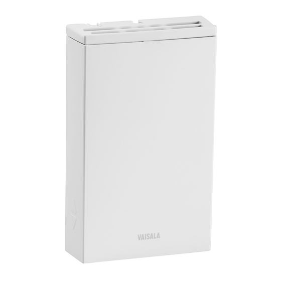
Figure 1 HMW90 Series Transmitters VAISALA ________________________________________________________________________ 11...
  • Page 14: Hmw90 Series Transmitters

    HMW90 HMW90 series wall-mount transmitter that has been TMW90 customized at Vaisala. Check type label on transmitter body and terminal label on the mounting base. Note for customized transmitters with analog outputs: Keep the transmitter in custom mode (DIP switch 8 set to custom) to retain the custom configuration.
  • Page 15: Output Parameters Explained

    Sum of the internal energy of a btu/lb thermodynamic system. NOTE Humidity parameters are not measured by TMW92, TMW93, and TMW90 transmitters even though the parameters can be selected using the service port (serial line and MI70 indicator use). VAISALA ________________________________________________________________________ 13...
  • Page 16: Transmitter Parts

    User's Guide _______________________________________________________________________ Transmitter Parts 1201-004 Figure 2 Transmitter Parts - Outside where 1 = Locking screw for mounting base. Not included, M3×6 recommended. 2 = Adjustment trimmers 3 = Service port 4 = Window for display (only in models where the display is visible) 5 = Locking screw for slide.
  • Page 17: Figure 3 Opening The Transmitter

    CAUTION When opening or closing the transmitter, avoid damaging the transmitter electronics with the two plastic supports on the mounting base. See Figure 4 on page 16 and Figure 5 on page 17. VAISALA ________________________________________________________________________ 15...
  • Page 18: Figure 4 Transmitter Parts - Inside (Analog Output Models)

    User's Guide _______________________________________________________________________ 1201-006 Figure 4 Transmitter Parts – Inside (Analog Output Models) where 1 = Mounting base 2 = Opening for cable (wiring from top) 3 = Terminal label 4 = Screw terminals 5 = Opening for cable (wiring from behind) 6 = Orientation arrow –...
  • Page 19: Figure 5 Transmitter Parts - Inside (Digital Output Models)

    11 = DIP switches for common configuration options; see section DIP Switches of Digital Output Models on page 24 12 = RS-485 termination jumper (connects a 120 Ω resistor) 13 = DIP switches for transmitter address selection 14 = HTM10 module ® 15 = HUMICAP sensor VAISALA ________________________________________________________________________ 17...
  • Page 20: Decorative Cover Option

    User's Guide _______________________________________________________________________ Decorative Cover Option The decorative cover is an installation accessory for HMW90 and GMW90 series transmitters that can be used to hide the transmitter from view. The cover material is transparent polycarbonate, but the idea is to customize it to match the wall the transmitter is on.
  • Page 21: Chapter 3 Installation

    These two configuration methods are mutually exclusive. If the DIP switch configuration is used, software settings have no effect on settings that are controlled by the DIP switches. DIP switch number 8 is the master switch that controls which configuration method is used. VAISALA ________________________________________________________________________ 19...
  • Page 22: Dip Switches Of Analog Output Models

    User's Guide _______________________________________________________________________ DIP Switches of Analog Output Models 1 2 3 4 5 6 7 8 1 2 3 4 5 6 7 8 HMW92/TMW92 HMW93/TMW93 1111-066 Figure 7 DIP Switch Settings of Analog Output Models Position Setting Non-metric Non-metric units (°F).
  • Page 23: Relay Configuration In Dip Mode

    - Relay contacts are open when transmitter is powered off. If you need to configure the relay for some other parameter or need additional configuration options, see section Relay Configuration in Custom Mode on page 54. VAISALA ________________________________________________________________________ 21...
  • Page 24: Figure 8 Relay High In Dip Mode (Hmw93)

    User's Guide _______________________________________________________________________ Rotary switch set to 6 (60 %RH) Relay closed DIP 5 set to “Relay High” Relay open Time 1111-117 Figure 8 Relay High in DIP Mode (HMW93) Relay closed Rotary switch set to 6 (60 %RH) DIP 5 set to “Relay Low” Relay open Time 1111-118...
  • Page 25: Changing Between Dip And Custom Configuration

    - Some configuration actions can be done using the BACnet and Modbus protocols. See the following appendices for protocol implementation details: - Appendix A, BACnet Reference, on page 82. - Appendix B, Modbus Reference, on page 95. VAISALA ________________________________________________________________________ 23...
  • Page 26: Dip Switches Of Digital Output Models

    User's Guide _______________________________________________________________________ DIP Switches of Digital Output Models Parity Even Modbus Non-Metric 128 64 32 16 8 1 2 3 4 5 6 7 8 2 3 4 5 6 7 8 Baud Address Rate Metric (Binary Weighting) BACnet Parity None HMW95 1209-016...
  • Page 27: Addressing With Bacnet Protocol

    BACnet MS/TP MAC address range is 0 … 255. The transmitter is a BACnet MS/TP master if address is below 128. Otherwise the transmitter is a slave. Addressing with Modbus Protocol Transmitter is always a Modbus slave. MAC Address range for Modbus slaves is 1 … 247. VAISALA ________________________________________________________________________ 25...
  • Page 28: Selecting Location

    User's Guide _______________________________________________________________________ Selecting Location The conditions at the location should represent well the area of interest. Do not install the transmitter on the ceiling. Avoid placing the transmitter near heat and moisture sources, close to the discharge of the supply air ducts, and in direct sunlight.
  • Page 29: Installing The Mounting Base

    (AWG14). You can bring the cable to the housing from above or from behind (recommended). After completing the wiring, connect the transmitter body over the mounting base. Note that mounting bases are model-specific. WARNING Connect only de-energized wires. VAISALA ________________________________________________________________________ 27...
  • Page 30: Figure 14 Wiring From Behind (Recommended)

    User's Guide _______________________________________________________________________ 1310-044 Figure 14 Wiring from Behind (Recommended) 1310-045 Figure 15 Wiring from Above 28 ___________________________________________________________________ M211399EN-G...
  • Page 31: Wiring Hmw92

    If you want to use a single power supply for the HMW92, you must connect the positive terminals (+T and +RH) together. Power supply 10 ... 28 VDC = 0 ... 600 Ω 1211-007 Figure 17 Three-Wire Wiring for HMW92 VAISALA ________________________________________________________________________ 29...
  • Page 32: Wiring Hmw93

    User's Guide _______________________________________________________________________ Wiring HMW93 Recommended wiring for long cables: Relay -RH +RH Power supply 18 ... 35 VDC or 24 VAC ±20% max. 50 VDC 500 mA = 10 kΩ min. 1111-068 Figure 18 Wiring HMW93 3-wire connection with -Vs as common ground. Maximum cable resistance is 2.5 Ω...
  • Page 33: Wiring Tmw92

    3-wire connection with -Vs as common ground. Maximum cable resistance is 2.5 Ω (24V supply, 0 ... 10 V output, relay not used). Relay Power supply 18 ... 35 VDC or 24 VAC ±20% = 10 kΩ min. 1202-119 Figure 22 Three-Wire Wiring for TMW93 VAISALA ________________________________________________________________________ 31...
  • Page 34: Wiring Hmw95

    User's Guide _______________________________________________________________________ Wiring HMW95 The RS-485 line of the transmitter is isolated from the power supply. A separate ground reference terminal (GND) is provided for the RS-485 connection. If you are using a shielded cable, you can use the Shld terminal to hold the exposed part of the shield.
  • Page 35: Connecting A Common Ac Power Supply To Several Transmitters

    This will avoid a short-circuit through the shared common line at the controller; see Figure 25 below. HMW90 CONTROLLER Supply Signal 24 VAC voltage output Shared common line HMW90 Supply Signal voltage output 1112-026 Figure 25 Connecting a Common AC Power Supply VAISALA ________________________________________________________________________ 33...
  • Page 36: Chapter 4 Operation

    User's Guide _______________________________________________________________________ CHAPTER 4 OPERATION This chapter contains information that is needed to operate the HMW90 series transmitters. Display Startup Screens When the transmitter is powered on, it displays a sequence of information screens. The screens are shown for a few seconds each. 1111-073, 1111-074 Figure 26 HMW93 Startup Screens...
  • Page 37: Measurement Screen

    HMW93 Measurement Screen – Normal Operation If there is a problem with measurement, affected readings are replaced with stars. The alarm indicator and an error message will also appear on the screen. 1111-072 Figure 28 HMW93 Measurement Screen – Problem With Measurement VAISALA ________________________________________________________________________ 35...
  • Page 38: Indicators On The Display

    Service Port You can connect to the service port on the HMW90 series transmitters using a computer or an MI70 indicator. The MI70 indicator is the hand- held display device that is included with, for example, the Vaisala ® HUMICAP Hand-Held Humidity and Temperature Meter HM70.
  • Page 39: Connecting With A Computer

    When connecting using a computer, use the Vaisala USB cable (Vaisala order code 219690) and a suitable terminal application: - If you have not used the Vaisala USB cable before, install the driver before attempting to use the cable. Refer to section Installing the Driver for the USB Service Cable on page 37 for detailed instructions.
  • Page 40: Terminal Application Settings

    Serial line to connect to field. Note: You can check which port the USB cable is using with the Vaisala USB Instrument Finder program that has been installed in the Windows Start menu. Check that the other serial settings are correct for your connection, and change if necessary.
  • Page 41: Figure 29 Putty Terminal Application

    Chapter 4 _________________________________________________________________ Operation 0807-004 Figure 29 PuTTY Terminal Application VAISALA ________________________________________________________________________ 39...
  • Page 42: List Of Serial Commands

    User's Guide _______________________________________________________________________ List of Serial Commands Some commands, such as RSEL, are not available if the required feature is not present on the transmitter, or the command is not relevant. All commands can be issued either in uppercase or lowercase. In the command examples, the keyboard input by the user is in bold type.
  • Page 43: Transmitter Information

    Use the VERS command to show the transmitter model and firmware version. VERS<cr> Example: >vers HMW93 / 1.00.0 Show Transmitter Serial Number Use the SNUM command to show the transmitter serial number. SNUM<cr> Example: >snum Serial number : G5130008 VAISALA ________________________________________________________________________ 41...
  • Page 44: Show Transmitter Status

    User's Guide _______________________________________________________________________ Show Transmitter Status Use the STATUS command to view detailed information on transmitter model and configuration. STATUS [function]<cr> where Function = Optional switch to display a more detailed status for BACnet or Modbus protocol (available on transmitter models with digital output).
  • Page 45 Chapter 4 _________________________________________________________________ Operation Example (display full status): >status Device Name : HMW92 Copyright : Copyright Vaisala Oyj 2012 SW Name : XM90 SW Model : XM9x SW version : 1.0.3.3728 Serial number : H1840005 Address SUB FUNCTIONS * Serial Port (COM1) *...
  • Page 46: Show Measured Parameters

    User's Guide _______________________________________________________________________ Show Measured Parameters Use the CALCS command to list the measurement parameters that are supported by the HMW90 series transmitters. RH and T are measured directly by the transmitter, the rest are calculated based on the measured values.
  • Page 47: Show Command List

    For HMW90 series transmitters you can set the ambient pressure value that is used for pressure compensation of calculated parameters. ENV [pressure]<cr> where pressure = Ambient pressure in hPa. Example: >env 1013.3 Pressure (hPa) : 1013.3 VAISALA ________________________________________________________________________ 45...
  • Page 48: Select Units

    User's Guide _______________________________________________________________________ Select Units Use the UNIT command to select metric or non-metric output units. Only affects data shown on the display and service port, has no effect on the analog and digital outputs. This command is not available on the digital output models (for example, HMW95).
  • Page 49: Set Analog Output Scaling

    = High limit of the scaling in the units of the selected parameter. Example (set channel 1 to output dewpoint, in the range -10 ... 20 °C): >pass 9000 >asel 1 TD -10 20 Aout 1 quantity : Td (-10.00 ... 20.00 'C) VAISALA ________________________________________________________________________ 47...
  • Page 50: Set Output Clipping And Error Limit

    User's Guide _______________________________________________________________________ Set Output Clipping and Error Limit Use the AOVER command to define the behavior of the analog outputs when the measured value is outside the scaled output range. AOVER [channel clip% valid%]<cr> where channel = Analog output channel, 1 or 2. clip% = Output margin (%) at which the output is clipped.
  • Page 51: Display Settings

    = Second parameter to show on the screen. Available parameters are the same as for Q1. = Third parameter to show on the screen. Available parameters are the same as for Q1. VAISALA ________________________________________________________________________ 49...
  • Page 52: Serial Line Output Commands

    User's Guide _______________________________________________________________________ Example (show currently displayed parameters): >pass 9000 >dsel Quant 1 Quant 2 : RH Quant 3 : Disabled Example (change display to only show RH): >dsel RH Example (change display to show same parameters as are assigned to analog output channels): >dsel out1 out2 Serial Line Output Commands...
  • Page 53: Output A Reading Once

    = time unit = "S", "MIN", or "H" The shortest output interval (with n = 0) outputs the measurement messages as quickly as the transmitter produces them, without additional delay. Example: >intv 1 min Output interval : 1 min VAISALA ________________________________________________________________________ 51...
  • Page 54: Set Output Format

    User's Guide _______________________________________________________________________ Set Output Format Use the serial line command FORM to change the measurement message sent by the transmitter on the service port. You can freely define the output message to include the desired parameters, formatting options, text strings, and additional fields. FORM [modifier string]<cr>...
  • Page 55: Serial Line Settings

    When entering modifiers, you can also use the backslash character “\” instead of the hash “#”. Serial Line Settings Set Remote Echo Use the ECHO command to enable or disable remote echo by the transmitter. ECHO [on/off]<cr> Example: >echo on Echo : ON VAISALA ________________________________________________________________________ 53...
  • Page 56: Set Serial Line Turnaround Delay

    User's Guide _______________________________________________________________________ Set Serial Line Turnaround Delay With the SDELAY command you can set the turnaround delay of the transmitter (time waited before replying to an incoming message) or view the currently set delay value. SDELAY [delay]<cr> where delay = Turnaround delay in milliseconds, range 1 … 1000. Default is 1.
  • Page 57: Set Relay Parameter And Limits

    Example (show current settings): >pass 9000 >rsel Relay configuration : RH (88.00 ... 92.00 %) Example (set temperature as relay parameter, low limit 25, high limit 30): >rsel t 25 30 Relay configuration : T (25.00 ... 30.00 'C) VAISALA ________________________________________________________________________ 55...
  • Page 58: Relay Configuration Examples

    User's Guide _______________________________________________________________________ Relay Configuration Examples RSEL RH 60 70 Relay closed RMODE Hi_Active Relay open Time 1111-119 Figure 30 Relay Hi_Active in Custom Mode (HMW93) Relay closed RSEL RH 60 70 RMODE Lo_Active Relay open Time 1111-120 Figure 31 Relay Lo_active in Custom Mode (HMW93) 56 ___________________________________________________________________ M211399EN-G...
  • Page 59: Calibration And Adjustment Commands

    The CRH command does nothing on the TMW92 and TMW93 NOTE transmitters. Show Current RH Adjustment CRH<cr> Example (showing default offset and gain): >pass 9000 >crh RH Gain : 1.000 RH Offset : 0.000 VAISALA ________________________________________________________________________ 57...
  • Page 60: 1-Point Adjustment Of Rh Measurement

    User's Guide _______________________________________________________________________ 1-point Adjustment of RH Measurement The 1-point adjustment adjusts both offset and gain depending on the adjustment condition. The same type of adjustment is done when turning the RH trimmer. Place the transmitter in the reference condition and allow it to stabilize before entering the adjustment.
  • Page 61: Clear User Adjustment Of Rh Measurement

    1-point Adjustment of T Measurement Place the transmitter in the reference condition and allow it to stabilize before entering the adjustment. CT [x]<cr> where The reference temperature (in degrees Celsius) that the transmitter should be showing. Example: >pass 9000 >ct 23 VAISALA ________________________________________________________________________ 59...
  • Page 62: Clear User Adjustment Of T Measurement

    User's Guide _______________________________________________________________________ Clear User Adjustment of T Measurement CT [RESET]<cr> Example: >pass 9000 >ct reset Enter Calibration and Adjustment Information Use the CTEXT command to store a text string that describes the calibration and/or adjustment. To enter a text string with spaces, enclose the string in quotation marks.
  • Page 63: Testing Commands

    : 0.00 ... 5.00 (error: 5.50) Example (set channel 1 to 6 V): >atest 1 6 Aout1 ( V) : 6.000 Example (end test mode for channel 1, resume normal output): >atest 1 Aout1 test mode disabled. VAISALA ________________________________________________________________________ 61...
  • Page 64: Test Relay Operation

    User's Guide _______________________________________________________________________ Test Relay Operation Use the command RTEST to test the operation of the relay. Issue the command without parameters to end the relay test. RTEST [state]<cr> where state = State of the relay contacts. Options are: open (open the relay contacts) closed (close the relay contacts) Example (close relay contacts): >pass 9000...
  • Page 65: Set Bacnet Parameters

    = Reinitializes the BACnet stack. Must be given as the only argument for the BACNET command. Example (show BACnet parameters): >bacnet Instance : 6 (00000006h) Name : HMW95_H2330001 Location : Location Description : Description Password : 1234 MAX_MASTER : 127 (007Fh) COV_Interval Autobaud_Interval : 10 VAISALA ________________________________________________________________________ 63...
  • Page 66 User's Guide _______________________________________________________________________ Example (change description to main_hall, and reinitialize the BACnet stack): >bacnet description main_hall Description : main_hall >bacnet reinit Reinitialize signaled to BACnet stack. 64 ___________________________________________________________________ M211399EN-G...
  • Page 67: Chapter 5 Maintenance

    - Adjustment Using a Computer on page 68. If adjustment is not enough to restore the measurement accuracy of the transmitter, you can also replace the measurement module. See section Replacing the Measurement Module on page 69. VAISALA ________________________________________________________________________ 65...
  • Page 68: Adjustment Using Display And Trimmers

    User's Guide _______________________________________________________________________ The adjustment of temperature measurement is always a simple 1-point offset correction. The 1-point humidity adjustment of the HMW90 series adjusts both offset and gain, depending on the adjustment condition. In a dry condition (for example, 11 %RH), offset is adjusted more than gain. NOTE The 1-point humidity adjustment requires that the target condition is at least 50% of the currently measured value.
  • Page 69: Adjustment Using An Hm70

    Adjustment Using an HM70 Connect the HMW90 series transmitter to the HM70 hand-held meter using the connection cable (Vaisala order code 219980). Depending on the connected devices, you may be prompted by the HM70 meter to check the currently applied environment settings.
  • Page 70: Adjustment Using A Computer

    HM70. Adjustment Using a Computer For more detailed instructions on using the Vaisala USB cable and a terminal application, see section Connecting With a Computer on page For a description of the serial commands, see section Calibration and Adjustment Commands on page 57.
  • Page 71: Repair Maintenance

    If you replace the module, you do not need to undo the previously applied correction. CAUTION Handle the HTM10 module carefully. When reinstalling the transmitter body to the mounting base, avoid touching the module or the ® HUMICAP sensor. VAISALA ________________________________________________________________________ 69...
  • Page 72: Figure 35 Replacing The Htm10 Module (Hmw93)

    User's Guide _______________________________________________________________________ To replace the module: Disconnect the transmitter body from the mounting base. With your fingers, push apart the two plastic holders that hold the module. Pull out the module. Keep the module straight while pulling it out, otherwise the pins may twist in the connector and damage it.
  • Page 73: Chapter 6 Troubleshooting

    2. If you are using remote echo on the transmitter, disable it with the ECHO OFF command to avoid collisions. 3. There may be an intermittent connection problem between the transmitter and your terminal. Issue the command again. VAISALA ________________________________________________________________________ 71...
  • Page 74: Error Messages

    User's Guide _______________________________________________________________________ Error Messages Table 12 Error Messages Error Text Error ID on Possible Cause Remedy on Display Serial Line HTM10 01 Communication Check that the HTM10 HTM10 02 problem with module sits firmly in place. HTM10 module. Remove and reconnect. HTM10 04 Problem with Check for missing or...
  • Page 75: Viewing Error Messages On Serial Line

    CRITICAL:OFF: HTM10 03 FLASH Corrupted ERROR:OFF: HTM10 04 RH measurement ERROR:OFF: HTM10 05 T measurement ERROR:OFF: HTM10 01 Continuous communication failure WARNING:OFF: HTM10 02 Single Communication failure WARNING:OFF: HTM10 06 Device Descriptor match WARNING:OFF: Factory parameter memory not consistent VAISALA ________________________________________________________________________ 73...
  • Page 76: Error State

    User's Guide _______________________________________________________________________ Error State If there are any active “critical” or “error” level errors active in the transmitter, both analog outputs are set into a defined error level instead of the measured result. The error level depends on the output type: - For 0 ...
  • Page 77: Reverting To Factory Settings

    Figure 37 on page 76. Do not move the switches in the other bank. 1 2 3 4 5 6 7 8 1 2 3 4 5 6 7 8 HMW92/TMW92 HMW93/TMW93 1203-018 Figure 36 DIP Switches in Factory Reset Position VAISALA ________________________________________________________________________ 75...
  • Page 78: Figure 37 Dip Switches In Factory Reset Position (Hmw95)

    User's Guide _______________________________________________________________________ Parity Even Modbus Non-Metric 2 3 4 5 6 7 8 Baud Rate Metric BACnet Parity None HMW95 1209-028 Figure 37 DIP Switches in Factory Reset Position (HMW95) Reconnect the transmitter cover to the mounting base so it powers up.
  • Page 79: Reverting To Factory Settings Using Service Port

    Resetting HMW93 / 1.00.00.0000 / XM90 > Technical Support For technical questions, contact the Vaisala technical support by e-mail at helpdesk@vaisala.com. Provide at least the following supporting information: - Name and model of the product in question. - Serial number of the product.
  • Page 80: Chapter 7 Technical Data

    ±3 %RH 90 ... 100 %RH ±4 %RH Stability in typical HVAC applications ±0.5 %RH/year ® Humidity sensor Vaisala HUMICAP 180R Temperature Measurement range -5 ... +55 °C (+23 ... +131 ºF) Accuracy +20 ... +30 °C (+68 ... +86 °F) ±0.2 °C (±...
  • Page 81: Table 15 Inputs And Outputs

    Selectable by DIP switch BACnet MS/TP Operating mode Selectable Master/Slave Address range, master mode 0 ... 127 Address range, slave mode 128 ... 255 Modbus RTU Address range 0 ... 247 Service port RS-485 line for temporary service use VAISALA ________________________________________________________________________ 79...
  • Page 82: Spare Parts And Accessories

    *RAL code is only indicative with potential small variations in color shade. Spare Parts and Accessories Information on spare parts, accessories, and calibration products is available online at www.vaisala.com and store.vaisala.com. Table 17 HMW90 Series Spare Parts and Accessories Description Order Code...
  • Page 83: Dimensions In Mm

    Chapter 7 _____________________________________________________________ Technical Data Dimensions in mm 1111-061 Figure 38 HMW90 Series Dimensions 59.5 29.8 30.5 1111-142 Figure 39 Dimensions of the Mounting Base VAISALA ________________________________________________________________________ 81...
  • Page 84: Appendix Abacnet Reference

    See section Configuration of Digital Output Models on page 23. BACnet Protocol Implementation Conformance Statement This statement is a part of the BACnet standard and is required for its use. Vendor Name: Vaisala Oyj Product Name: XMW90 Product Model Numbers: HMW95 Applications Software Version: 1.0.28...
  • Page 85  MS/TP slave (Clause 9), baud rates: 9600, 19200, 38400, 57600, 76800, 115200  Point-To-Point, EIA 232 (Clause 10), baud rates: ________  Point-To-Point, modem (Clause 10), baud rates: ________ ®  LonTalk protocol (Clause 11), medium: ________  Other: VAISALA ________________________________________________________________________ 83...
  • Page 86 User's Guide _______________________________________________________________________ Device Address Binding   Is static device binding supported? (required for two-way communication between MS/TP slaves and other devices) Networking Options  Router, Clause 6:  Annex H, BACnet Tunneling Router over IP  BACnet/IP Broadcast Management Device (BBMD) Does the BBMD support registrations by ...
  • Page 87: Device Object

    Note the following: - Writable means writable via BACnet. - Max_Master and Max_Info_Frames are required in a Master device. - UV = Configured at Vaisala factory to a unique value. See additional information after the table. Table 18 Device Object Properties...
  • Page 88 Object_Identifier: Must be unique in BACnet network. As Object Identifier is 22 bits long its value range is 0 ... 4194303. Each device is assigned a random value in this range at Vaisala factory. Object_Name: Must be unique in BACnet network. Default object name contains the name and serial number of the device.
  • Page 89: Relative Humidity Object

    No contact to measurement module 2 OVER_RANGE RH over 100% 3 UNDER_RANGE RH under 0% 7 UNRELIABLE_OTHER Other measurement error Table 22 Event State State Cause 0 NORMAL Reliability equals 0 (NO FAULT DETECTED) 1 FAULT Reliability not 0 VAISALA ________________________________________________________________________ 87...
  • Page 90: Calculated Humidity Objects

    62/64 (ºC/ ºF) "a" "Absolute humidity" 217/2000 grams-per-cubic-meter / grains-per-cubic-foot (Vaisala defined unit) "x" "Mixing ratio" 28/2001 grams-of-water-per-kilogram-dry-air / grains-of- water-per-pound (Vaisala defined unit) "h" "Enthalpy" 149/24 kilojoules-per-kilogram-dry-air / btus-per-pound-of- dry-air Table 24 Calculated Humidity Object Properties Property Data type...
  • Page 91: Table 26 Reliability

    No contact to measurement module 2 OVER_RANGE RH over 100% 3 UNDER_RANGE RH under 0% 7 UNRELIABLE_OTHER Other measurement error Table 27 Event State State Cause 0 NORMAL Reliability equals 0 (NO FAULT DETECTED) 1 FAULT Reliability not 0 VAISALA ________________________________________________________________________ 89...
  • Page 92: Temperature Object

    User's Guide _______________________________________________________________________ Temperature Object Table 28 Temperature Object Properties Property Data type Writable Value or Initial Value Persistence (Application Type) (Conformance Code) Object_Identifier BACnetObjectIdentifier No (R) 00 00 00 03 (hex) Nonvolatile Object Type = 0, Instance = 3 Object_Name CharacterString No (R)
  • Page 93: Operation Pressure Object

    BACnet Event State 0 (NORMAL, does not change) Out of Service BOOLEAN 0 (FALSE) Table 33 Status Flags Flag State Cause IN_ALARM FALSE Always FALSE FAULT FALSE Always FALSE OVERRIDDEN FALSE Always FALSE OUT_OF_SERVICE FALSE Always FALSE VAISALA ________________________________________________________________________ 91...
  • Page 94: Operation Altitude Object

    User's Guide _______________________________________________________________________ Operation Altitude Object Set current atmospheric pressure to improve the calculation accuracy of pressure dependent humidity parameters. NOTE Pressure and Altitude objects are linked together. If Present Value in one object is changed, Present Value in another object is changed accordingly.
  • Page 95: Table 36 Bacnet Smart Sensor Bibbs Support

    Device Management - UTC Time Synchronization - B DM-UTC-B  Device Management - Reinitialize Device - B DM-RD-B  Device Management - Backup and Restore - B DM-BR-B  Network Management - Connection Establishment - A NM-CE-A  VAISALA ________________________________________________________________________ 93...
  • Page 96: Table 37 Bacnet Standard Application Services Support

    User's Guide _______________________________________________________________________ Application Services Supported Table 37 below lists all the BACnet standard application services. The checked services are supported by the device. Table 37 BACnet Standard Application Services Support Application Service Initiates Requests Executes Requests AcknowledgeAlarm   AddListElement ...
  • Page 97: Table 38 Modbus Functions Supported By Hmw90

    0017…0018 0265 (×0.01) g/kg 6417…0018 6465 (×0.01) gr/lb 0019…0020 0266 (×0.01) kJ/kg 6419…0020 6466 (×0.01) btu/lb Values read from the integer registers must be multiplied with the provided multiplier to get the actual value. All integer values are signed. VAISALA ________________________________________________________________________ 95...
  • Page 98: Table 40 Hmw90 Modbus Status Registers (Read-Only)

    User's Guide _______________________________________________________________________ Available measurements depend on the transmitter model. Values may be unavailable also in case of device failure. Read status registers or exception status outputs to check for failures. Accessing unavailable (unsupported or temporarily missing) measurement data does not generate an exception.
  • Page 99: Vaisala

    Information text of the last calibration (empty if not available) Table 44 HMW90 Modbus Exception Responses Code Name Reason ILLEGAL FUNCTION Unsupported function code ILLEGAL DATA ADDRESS Address out of valid ranges ILLEGAL DATA VALUE Otherwise invalid request VAISALA ________________________________________________________________________ 97...
  • Page 100 *M211399EN*...

Table of Contents