Table of Contents
Advertisement
Advertisement
Table of Contents
Troubleshooting

Related Manuals for Aeon Cobra 220


Summary of Contents for Aeon Cobra 220
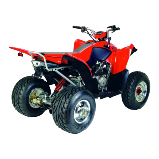
- Page 1 AEON MOTOR CO., LTD SERVICE MANUAL...
-
Page 2: Table Of Contents
CONTENTS INFORMATION………………………………………... MAINTENANCE…………………….………………… ENGINE REMOVAL AND INSTALLATION………… LUBRICATION………………………………………… CYLINDER HEAD / VALVES……………………….. CYLINDER & PISTON………………………………... TRANSMISSION & KICKSTARTER………………… FRONT WHEEL, SUSPENSION AND STEERING….. REAR WHEEL SYSTEM……………………………… FENDERS AND EXHAUST PIPE…………………….. ELECTRICAL SYSTEM………………………………. TROUBLE SHOOTING……………………………….. -
Page 3: Information
1. INFORMATION 1.1 Safety 1.2 Notes 1.3 Specifications 1.4 Serial number 1.5 Torque valve 1.1 SAFETY GASOLINE Gasoline is extremely flammable and is explosive under certain condition. Do not smoke or allow sparks or flames in your work area. CARBON MONOXIDE Never run the engine in a closed area. - Page 4 1.3 SPECIFICATION ENGINE Air-cooled 4-stroke , vertical Type cylinder Displacement 195.8 cc Bore and Stroke 65×59mm 9.6:1 Compression 1.45 N-m @ 5000 rpm Maximum Torque Carburetor Mikuni Ignition C.D.I Electronic Starting Electrical & Kick-Start Wet Sump Lubrication Air Cleaner AE-9 Transmission Automatic(C.V.T sysetm with reverse gear)
- Page 5 1.4 SERIAL NUMBER The frame serial number is stamped on the front frame. And stick a bar code paper to cover it. The engine number is stamped under the crankcase.
- Page 6 1.5 TORQUE VALVES STANDARD 5 N.m (3.5 lbs.ft) 5mm bolt and nut 10 N.m (7.2 lbs.ft) 6mm bolt and nut 22 N.m (16 lbs.ft) 8mm bolt and nut 35 N.m (25 lbs.ft) 10mm bolt and nut 55 N.m (40 lbs.ft) 12mm bolt and nut ENGINE 18~22 N.m (13~16 lbs.ft)
-
Page 7: Maintenance
2. Maintenance Maintenance data Maintenance schedule Throttle operation Air cleaner maintenance Spark plug Idle speed setting Drive chain adjustment Brake system adjustment Wheels and tires 2.10 Steering system 2.11 Toe-alignment 2.12 Transmission lubrication 2.1 MAINTENANCE DATA SPECIFICATION SPARK PLUG 0.6-0.7mm Spark plug cap NGK CR7HSA Recommended spark plugs... - Page 8 2.2 MAINTENANCE SCHEDULE The maintenance intervals in the follow table is based upon average riding, condition. Riding In usually dusty areas, require more frequent servicing. Item Maintenance Interval Remarks (whichever comes first) Calender Miles(Km) Hours ¡ » Engine breather 250 (400) Inspect; replace if necessary filter (if equipped) Engine breather 100H...
- Page 9 Item Maintenance Interval Remarks (whichever comes first) Miles(Km) Hours Calender ¡ ½ Fuel system 100H 12 M 1000 Check for leaks at tank cap, lines, (1600) fuel valve, filter, pump, carburetor; replace lines every two years ¡ ½ Fuel filter 100H 12 M 1000...
- Page 10 2.3 THROTTLE OPERATION Inspect for smooth lever operation, full opening and automatic full closing in steering positions. Inspect for deterioration, damage, cuts and nicks, or kink in the throttle cable, replace it if necessary. Check the throttle lever, free play should be not more than 5-10 mm at the tip of the throttle lever.
- Page 11 2.4 AIR CLEANER MAINTENANCE (1) Lift up on the rear of the seat. (2) Pull the seat back and free of the tabs. NOTE: When reinstalling seat, make sure the slots in the seat engage the tabs in the fuel tank. (3) Remove clips from air box cover (A) and remove cover.
- Page 12 2.5 SPARK PLUG The spark plug is located at the front of the engine. (1) Disconnect the spark plug cap and remove The spark plug (2) Visually inspect the spark plug electrodes For wear or cranks in insulator. Replace if needed.
- Page 13 2.7 DRIVE CHAIN ADJUSTMENT Stop ATV and shift transmission into neutral. Inspect the chain slack midway between the sprockets. The standard is 10-25 mm (5/8-1 inch). If needed remove the chain protective cover and adjust the chain slack. Loosen the axle holder lock nut then adjust the drive chain slack by turning the adjusting nut.
- Page 14 2.8 BRAKE SYSTEM ADJUSTMENT Inspect the front brake lever and cable for excessive play or other damage. Replace or repair if necessary. Measure the free play of the brake lever at the end of the lever. The standard is 10~20 mm. Adjust the free play of the front brake lever by turning the adjuster on the brake lever assembly.
- Page 15 2.9 WHEELS AND TIRES Inspect the tire surface for cuts, nails or other sharp objects. Check the tire pressure at cold tire conditions. The standard tire pressure is 4psi. (0.28kgf/cm 2.10 STEERING SYSTEM Check the free play of the steering shaft with the front wheels, turned straight ahead.
- Page 16 2.11 TOE-ALIGNMENT 1. Place machine on a smooth level surface. 2. Set handlebars in a straight ahead position and secure handlebars in this position. NOTE: The steering arm can be used as an indicator of whether the handlebars are straight. The arm should always point straight back from the steering post.
- Page 17 2.12 TRANSMISSION LUBRICATION Transmission fluid needs to be changed every 400 km. There is a gear oil drain hole bolt at the rear of the engine. (STEP1) Place a drain pan beneath oil pan and remove drain plug from the crankcase. Allow oil to drain completely.
-
Page 18: Engine Removal And Installation
3 ENGINE REMOVALS AND INSTALLATION 3.1 ENGINE REMOVAL 3.2 ENGINE REPLACEMENT ENGINE SHOULD ONLY BE REMOVED IN THE CONDITIONS OF NECESSARY REPAIRS OR ADJUSTMENT TO THE TRANSMISSION AND COMBUSTION SYSTEM ONLY! 3.1 ENGINE REMOVAL 1. Clean work area. 2. Thoroughly clean the ATV engine and chassis. - Page 19 3.2 ENGINE REPLACEMENT Engine installation is essentially the reverse order of removal. The torque of engine hanger bolt is 30 Nm Route the wires and cable properly in reverse order of removal.
-
Page 20: Lubrication
4. LUBRICATION 4.1 Service Information 4.2 Trouble Shooting 4.3 Engine Oil Level 4.4 Engine Oil & Filter Change 4.5 Oil Pump Removal /Installation 4.1 SERVICE INFORMATION GENERAL This section describes inspection and replacement of the engine oil, oil filter screen and assembly of the oil pump. - Page 21 4.2 TROUBLE SHOOTING Oil level too low / high oil consumption Normal oil consumption. External oil leaks. Oil not changed often enough. Worn piston rings. Faulty heat gasket. Oil contamination Worn piston rings. Faulty heat gasket. Oil or filter not changed often enough. 4.3 ENGINE OIL LEVEL To check the oil level: 1.
- Page 22 4.4 ENGINE OIL & FILTER CHANGE 1. Place vehicle on a level surface. 2. Clean area around drain plug at bottom of oil pan. 3. Run engine two to three minutes until warm. Stop engine. 4. Place a drain pan beneath oil pan and remove drain plug from under the crankcase.
- Page 23 13. Place gear selector in neutral and set parking brake. 14. Start the engine and let it idle for one to two minutes, Stop the engine and inspect for leaks. 15. Re-check the oil level and add oil as necessary to bring the level to the upper level.
- Page 24 CAUTION: The crankshaft end contains an oil passage plunge joint (A) as shown below. The plunger must be able to move in and out freely. Avoid damage to the crankshaft end or plunge joint and spring, which can cause loss of oil pressure, resulting in severe engine damage.
- Page 25 10. Using the Slotted Nut Socket, remove the crankshaft slotted nut (A). NOTE: Slotted nut is left hand thread. 11. Remove cam chain drive sprocket (B) and Woodruff key from crankshaft.. 12. Inspect sprocket teeth for wear or damage. 13. Inspect Woodruff key for wear. 14.
- Page 26 22. Remove the oil pump drive gear. 23. Remove the oil pump retaining screws. 24. Inspect the sprockets and chain for wear or damage. Inspect chain for worn or missing rollers or damage. Replace chain anytime the oil pump is replaced or if excessive ly worn.
- Page 27 OIL PUMP ASS’Y / INSTALLATION 1. Install the crankshaft gear, woodruff key and slotted nut. 2. Install the balance shaft gear and align the mark with the crankshaft gear mark as shown. 3. Install the woodruff key.
- Page 28 4. Install the oil pump. 5. Install the chain (A) over the sprocket on the balance shaft gear (B). 6. Install the washer and nut. Torque to specification.
- Page 29 7. Install the oil pump galley. 8. Install flywheel key, flywheel washer, and nut. 9. Install stator housing.
-
Page 30: Cylinder Head / Valves
5. CYLINDER HEAD / VALVES 5.1 SERVICE INFORMATION 5.2 TROUBLESHOOTING 5.3 CAMSHAFT ASS’Y REMOVAL 5.4 CYLINDER HEAD REMOVAL 5.5 CYLINDER HEAD INSTALLATION 5.1 SERVICE INFORMATION GENERAL This section describes the maintenance of cylinder head, valves, camshaft and the other parts. The engine must be removed from the frame to service cylinder head. - Page 31 5.2 TROUBLE SHOOTING Engine top-end problems usually affect engine performance. These problems can be diagnosed by a compression test, or by tracing engine noise to the top end with a sounding rod or stethoscope. Low compression valve Incorrect valve adjustment. Worn or damaged valve seats.
- Page 32 5.3 CAM SHAFT ASS’Y REMOVAL Remove the cylinder head cover. Remove the two cam chain tensioner falange bolts. Remove the nuts(A) and washers Remove the camshaft holder and dowel pins.
- Page 33 Remove the rocker shaft locking plate. Inspect each rocker arm cam follower surface. If there is any damage or uneven wear, replace the rocker arm. NOTE: Always inspect camshaft lobe if rocker arms are worn or damaged. Remove each rocker arm shaft using the 10 mm hex bolt that secures the lock plate.
- Page 34 Remove the 4 cylinder head bolts evenly by loosening each one 1/4 turn at a time until loose. Remove the cam chain from the sprocket by tilting the cam assembly and simultaneously lifting the chain. INSPECTION Inspect the cam lobes surface and height of cam lobes for wear or damage.
- Page 35 5.4 CYLINDER HEAD REMOVAL Loosen each of the four cylinder head bolts evenly 1/4 turn each time in a cross pattern until loose. Remove bolts (A) Remove cylinder head and head gasket. CYLINDER HEAD DISASSEMBLY Using a valve spring compressor, compress the valve spring and remove the spilt keeper.
- Page 36 Push valve out, keeping it in order for reassembly in the same guide. Measure free length of the inner and outer springs with a Vernier caliper, |||.1. Check spring for squareness as shown in |||.2. Replace spring if measurements are out of specification.
- Page 37 Check end of valve stem for flaring, pitting , wear or damage (A). Inspect split keeper groove for wear or flaring of the keeper seat area (B) NOTE: The valves cannot be re-faced or end ground. They must be replaced if worn, bent, or damaged.
- Page 38 CYLINDER HEAD ASS’Y CAUTION: Wear eye protection during assembly. NOTE: Assemble the valves one at a time to maintain proper order. Install new valve seals on valve guides. Apply engine oil to valve guides and seats. Coat valve stem with molybdenum disulfide grease.
- Page 39 5.5 CYLINDER HEAD INSTALLATION Install the dowel pin(s) and a new cylinder head gasket. Pull the cam chain through the cylinder head chain room and secure with mechanic’s wire. Place the cylinder head on the cylinder. Install the two 6 mm bolts, but do not tighten. Install the cam according to the “Cam shaft Timing”...
- Page 40 Install the camshaft. Disconnect the wire securing the cam chain and loop the cam chain over the sprocket while verifying the cam is inserted with the alignment marks parallel to the gasket surface. Apply clean engine oil liberally to the valve springs, cam chain, rocker arms, and camshaft.
-
Page 41: Cylinder & Piston
6. CYLINDER AND PISTON 6.1 SERVICE INFORMATION 6.2 TROUBLESHOOTING 6.3 CYLINDER REMOVAL 6.4 PISTON REMOVAL 6.5 PISTON INSTALLATION 6.6 CYLINDER INSTALLATION 6.1 SERVICE INFORMATION GENERAL Camshaft lubrication oil is fed to the cylinder head through an oil orifice in the cylinder head and engine case. - Page 42 6.2 TROUBLESHOOTING Low or unstable compression Worn cylinder or piston rings. Overheating Excessive carbon build-up on piston or combustion chamber wall. Knocking or abnormal noise Worn piston and cylinder. Excessive carbon build-up. Excessive smoke Worn cylinder, piston, or piston rings. Improper installation of piston rings Scored or scratched piston or cylinder wall.
- Page 43 6.3 CYLINDER REMOVAL Remove bolts (A) and tap the cam support tower with a plastic hammer until loose. After removing the camshaft and securing the cam chain, tap cylinder head lightly with a plastic hammer until loose. Remove the cylinder head and head gasket. Remove cam chain guide at front of cylinder.
- Page 44 6.4 PISTON REMOVAL Remove circlip. Note that opening for circlip access is on the exhaust side. Remove piston circlip and push piston pin out of piston. If necessary, heat the crown of the piston slightly with a propane torch. CAUTION: Do not apply heat to the piston rings.
- Page 45 INSPECTION Remove all gasket material from the cylinder sealing surfaces. Inspect the top of the cylinder for warpage using a straight edge and feeler gauge. Inspect cylinder for wear, scratches, or damage. Inspect cylinder for taper and out of round with a telescoping gauge or a dial bore gauge.
- Page 46 PISTON INSPECTION Measure piston outside diameter at a point 7 mm up from the bottom of the piston at a right angle to the direction of the piston pin. Subtract this measurement from the maximum cylinder measurement obtained earlier. Measure piston pin bore. Replace piston if out-of-round.
- Page 47 Measure connecting rod small end ID. Replace crankshaft if out-of round. Measure piston ring to groove clearance by placing the ring in the ring land and measuring with a thickness gauge. Replace piston and rings if ring-to-groove clearance exceeds service limits.
- Page 48 Install a new circlip on one side of the piston with the end gap facing up or down. Apply clean engine oil to the piston rings, ring lands, piston pin bore, piston pin, and piston skirt. Lubricate the connecting rod (both ends) and crankshaft main bearing area.
- Page 49 6.6 CYLINDER INSTALLATION NOTE: Clean the gasket surfaces on the crankcase and cylinder. Remove all traces of old gasket material and apply a new base gasket. Install the dowel pin(s). Install a new base gasket onto the mating surface. NOTE: Route cam chain through the cylinder chain room and secure it, holding it up while rotating the engine to avoid damage to the chain, drive sprocket teeth or tensioner blade.
-
Page 50: Transmission & Kickstarter
7. TRANSMISSION & KICK STARTER 7.1 SERVUCE INFORMATION 7.2 TROUBLESHOOTING 7.3 C.V.T SYSTEM DISASSEMBLY / DRIVE CLUTCH 7.4 KICK STARTER ASSEMBLY 7.5 KICK STARTER ASSEMBLY 7.6 C.V.T REASSEMBLY 7.1 SERVICE INFORMATION If the drain tube ass’y fills with water, the tube should be drained. SPECIFICATIONS ITEM STANDARD (mm) - Page 51 7.2 TROUBLESHOOTING Engine starts but can’t travel Worn driven belt. Worn clutch lining. Damaged driven face spring. Low engine power Worn driven belt. Worn weight roller. Dirty driven face.
- Page 52 7.3 C.V.T SYSTEM DISASSEMBLY / DRIVE CLUTCH Remove the side cover and drive belt. Remove the lock nut, washer, and the kick-start pawl from the crankshaft. Remove the fixed sheave (A), starter pawl (B) and slide bushing (C). Inspect the fixed sheave and slide bushing for scoring, grooving, or abnormal wear.
- Page 53 NOTE: Use two hands to hold the cam plate and the primary sliding sheave together when removing the primary sliding sheave and the cam plate assembly. This prevents the roller weights from falling out of the assembly. Remove the roller weights from the primary sliding sheave.
- Page 54 Remove the driven clutch assembly by releasing the set screw and removing the nut from the shaft. Pull the entire clutch off as an assembly. Set the driven clutch assembly on a flat surface. Remove the cover, spring washer stack, and ball bearing retainer.
- Page 55 Remove the ball bearings. Use a snap-ring pliers to remove the retainer on the hold cam. Remove the washer. Inspect the hold cam for excessive spline wear or damage. Replace the component if required. Inspect the condition of the clutch drum. Measure the inside diameter of the cover at 90 degree intervals using a caliper.
- Page 56 NOTE: Outer sheave retaining nut replacement is strongly recommended. Use Loctite upon reassembly. Use a vemier caliper to check the length of the compression spring. At full extension, the measurement should be no less than 3.50” (89 mm). If out of specification, replace the spring. Remove the outer roller pin cover by turning and pulling up on the cover.
- Page 57 To replace the friction shoes, remove the e-clips that retain the backing plate. Use a suitable tool to remove and install the springs connecting the shoes, using care not to over-stretch the springs more than is necessary. To reassemble the driven assembly, reverse the disassembly procedures.
- Page 58 7.4 KICK STARTER DISASSEMBLY Remove the crankcase cover. KICK STARTER CRANKCASE COVER Remove the Kick starter. Remove the ex. Circle-clip and washer from kick starter spindle composition. EX. CIRCLIP Remove the kick-starter spindle ass’y. STARTER SPINDLE ASS’Y Remove the kick-starter idle gear ass’y Remove the kick spindle bush.
- Page 59 Inspect the kick-starter return spring for KICK SPINDLE BUSH fatigue or damage. Inspect the kick-starter spindle bush for wear of damage. KICK RETURN SPRING Inspect the kick driven gear and spring for wear or damage. KICK DRIVEN SPRING 7.5 KICK-STARTER ASSEMBLY Install the kick driven gear and spring.
- Page 60 Install the kick-starter. 7.6 C.V.T REASSEMBLY Install the driven assembly onto the transmission input shaft. Do not tighten the nut at this time. Install the bushing, the primary sliding sheave, and the cam plate assembly. NOTE: When installing the primary sliding sheave and the cam plate assembly, hold the cam plate and the primary sliding sheave together.
- Page 61 Install the drive belt by looping the belt over the loosened drive and driven clutches. Finish installing the lock nut and washer onto the crankshaft. Torque the drive clutch nut to specification. CVT Drive Clutch Nut Torque 40 ft. lbs. (55 Nm).
- Page 62 8. FRONT WHEEL, SUPENSION AND STEERING 8.1 PARTS DRAWING 8.2 TROUBLESHOOTING 8.3 HANDLEBAR SYSTEM 8.4 THROTTLE HOUSING 8.5 FRONT WHEEL 8.6 FRONT BRAKES 8.7 STEERING SYSTEM 8.1 PARTS DRAWING...
- Page 64 8.2 TROUBLESHOOTING HARD STEERING Faulty tire Steering shaft holder too tight Insufficient tire pressure Faulty steering shaft bushing Damaged steering shaft bushing FRONT WHEEL WOBBLING Faulty tire Worn front brake drum bearing Bent rim Axle nut not tightened properly BRAKE DRAG Incorrect brake adjustment Sticking brake cable Bent tie rods...
- Page 65 8.3 HANDLEBAR SYSTEM Removal Remove the handlebar cover by unscrew two fix screws. Remove the throttle lever housing on the right handlebar. Remove brake lever bracket assembly. Remove the handlebar switch on the left handle bar. Remove rear brake lever bracket ass’y. Remove the bolts attaching the handlebar upper holder.
- Page 66 Installation Install the switch housing. Tighten two screws securely. Install the throttle lever housing, and brake lever bracket ass’y.
- Page 67 8.4 THROTTLE HOUSING Disassembly Unscrew the screws on the throttle housing cover. Remove throttle housing cover and gasket. Disconnect throttle cable from the throttle arm and remove from the throttle housing. Assembly is in the reverse order of disassembly. 8.5 FRONT WHEEL Remove Raise the front wheels off the ground by placing a jack or other support under the frame.
- Page 68 Remove the caliper bolts (B) and caliper from the mount bracket. With pads installed, push caliper piston into caliper bore slowly using a C-clamp or locking pliers. NOTE: Brake fluid will be forced through compensating port into master cylinder fluid reservoir when piston is pushed back into caliper.
- Page 69 Remove the loose caliper slide bolts. The brake pad (D) will slide out of the caliper assembly when the caliper slide bolt is removed. Measure the thickness of the pad material. Replace pads if worn beyond the service limit. FRONT PAD ASSEMBLY WARNING: If the brake pads are contaminated with grease, oil, or liquid soaked do not use the pads, use only new clean pads.
- Page 70 Install caliper on the steering knuckle, and torque mounting bolts. (If previously removed.) Use an Allen wrench or socket to torque the front caliper bolts to 33 ft. lbs. (45 Nm). Slowly pump the brake lever until pressure has been built up. Maintain at least 1/2” (12.7 mm) of brake fluid in the reservoir to prevent air from entering the brake system.
- Page 71 FRONT DISC INSPECTION Visually inspect the brake disc for nicks, scratches, or damage. Measure the disc thickness at 8 different points around the pad contact surface using a 0-1” micrometer. Replace disc if worn beyond service limit. Brake Disc Thickness New 0.150-0.164”...
- Page 72 FRONT BRAKE DISC REMOVAL / REPLACEMENT Apply heat to the hub in the area of the brake disc mounting bolts to soften the bolt locking agent. Remove bolts and disc. Clean mating surface of disc and hub. Install disc on hub. CAUTION: Always use new brake disc mounting bolts.
- Page 73 Using a line wrench, loosen and remove brake line (A) to caliper. Place a container under caliper to catch fluid draining from brake line. Drain the fluid into the container. Remove the two brake caliper mounting bolts (B) and remove the brake caliper. FRONT CALIPER INSTALL Install caliper on hub strut, and torque mounting bolts to 18 ft.
- Page 74 FRONT CALIPER DISASSEMBLY Remove the c-clips (A) from the caliper sliding bolts. Remove the caliper slide bolts (B), mounting bracket (C), and brake pads (D). Remove the outside dust boot (E). Remove the piston and dust seal (F).
- Page 75 Remove the caliper body bolts (G). Pull the caliper bodies apart (if necessary). Clean the caliper body, piston, and retaining bracket with brake cleaner or alcohol. NOTE: Be sure to clean seal grooves in caliper body. FRONT CALIPER INSPECTION Inspect caliper body bore for nicks, scratches or wear.
- Page 76 FRONT CALIPER ASSEMBLY Reassemble the two caliper halves if previously disassembled. Torque the caliper body bolts to 18 ft. lbs. (24 Nm). Install new O-ring (A) in the caliper body. Install the dust boot over the caliper and seat the dust boot into caliper groove.
- Page 77 8.7 STEERING SYSTEM Remove wheel nuts and wheel. Remove the spacer (A) located on the backside of the wheel. Remove the two brake caliper hex bolts (B) and the brake caliper. Remove hub cap (C), cotter pin, front spindle nut, and washer. Remove the outer spacer (D) from the spindle.
- Page 78 Remove the hub (E) from the spindle. Remove the inner spacer (F), the spacer maybe in the hub or located on spindle during removal. Inspect the inner spacer for wear, replace if needed. Remove the upper and lower ball joint cotter keys and castle nuts.
- Page 79 Elevate front end of machine so front wheels are off the ground. Check for any looseness in front hub / wheel assembly by grasping the tire firmly at top and bottom first, and then at front and rear. Try to move the wheel and hub by pushing inward and pulling outward.
- Page 80 Steering shaft inspection Inspect the steering shaft for damage or cracks. Installation of steering shaft Apply grease to the holder. Install the holder and oil seal tighten with the nuts. Torque : 33 N.m(24 lbs-ft) Installation of steering shaft Install the steering shaft nut and tighten it. This nut is under this steering shaft.
-
Page 81: Rear Wheel System
9. REAR WHEEL SYSTEM 9.1 PARTS DRAWING 9.2 TROUBLESHOOTING 9.3 REMOVE REAR WHEEL AND REAR BRAKE 9.4 DRIVE MECHNISM 9.1 Parts Drawings... - Page 82 9.2 Troubleshooting Brake shoes are worn Bad Brake Performance Bad brake adjustment Brake lining are oily, greasy or dirty Brake drums are worn Brake arm setting is improperly engage Axle is not tightened well Vibration or wobble Bent rim Axle bearings are worn Faulty tires Rear axle bearing holder is faulty Brake Drag...
- Page 83 Brake Parts & Location Handlebar Rear Brake Cable Front Brake Cable Foot Brake Padal Front Brake Oil Tube Hydraulic Cylinder Driving Rod Brake Pump Rear Brake Oil Tube Rear Brake Caliper The cable connectsto Hydraulic Cylinder the left side brake Driving Rod lever.
- Page 84 Brake Oil Tank Right Side Left Side Brake Lever Brake Lever The cable connects to rear brake disc The cable connects to front brake disc...
- Page 85 Brake Oil Tube Rear Brake Caliper The Brake Adjustment Rear Brake Cable Fixing Set (STEP.1) Take off the rear brake fixing set and the bolt of brake pump.
- Page 86 Hydraulic Clyinder Driving Adjusting Bolt (STEP.2) The setup of the adjusting nut of the brake pump: 1. The brake pedal should be in the highest location under the function of the returning spring. 2. The adjusting nut changes the distance between the brake pump and the hydraulic cylinder driving rod.
- Page 87 (STEP.3) Drain the air in the brake oil tube in order to prevent the brake pump malfunction in power delivering. 1. Open the brake oil tank, lose the drain screw of the brake caliper without braking motion. It functions normal if the brake oil could drain automatically, please try this for couple times for confirmation.
- Page 88 Adjusting Screw Rear Brake Cable Fixing Gap(2~3mm) Brake Cable Gap Adjuster (STEP.4) Install the rear brake cable fixing set & adjust the brake cable. 1. Spin the gap adjuster on the left lever till the shortest position. 2. Adjust the adjusting screw and keep the gap being 2-3 mm. Rear Brake Balance Adjustment Front Brake...
- Page 89 Left / Right Front Brake Balance Adjuster. (STEP.5) The brake balance adjuster on right lever. 9.4 DRIVE MECHNISM Removal and inspection. Remove the rear wheel and the rear brake. Remove the skid plate under swing arm. Remove the drive chain cover. Disassemble the chain retaining clips and master link.
- Page 90 Disassemble the driven sprocket, axle and sprocket collar. Check the driven sprocket for damage or wear. Replace if necessary. Let the rear axle lie in V-blocks and check the runout. The runout limit is 0.5 mm. Check the turning of inner race of bearing with fingers.
- Page 91 Assemble the drive chains on the driven sprocket. Assemble the master link and retaining clip. NOTE: The retaining clip direction. Install the drive chain cover. Assemble the chain under cover. Install the skid plate. Install the drive chain cover.
-
Page 92: Fenders And Exhaust Pipe
10. FENDER AND EXHAUST PIPE 10.1 REAR FENDER REMOVAL 10.2 FRONT FENDER REMOVAL 10.3 EXHAUST PIPE REMOVAL 10.4 EXHAUST PIPE INSTALLATION 10.1 REAR FENDER REMOVAL Pull the “Seat Release Bar” to take off the seat. This seat release bar is under the right side of the rear fender. - Page 93 10.2 FRONT FENDER REMOVAL Front Cab: 2 screws at rear of cab to frame, 2 screws at front of cab to frame, 8 screws secure footwell to front cab (unless removed previous). Side Covers: 2 plastic inserts and 1 screw ( each side)
- Page 94 10.3 EXHAUST PIPE REMOVAL You must wait at least 15 minutes after turn off the engine. You need to remove the seat, rear fender and footrest plate, before you take off the exhaust pipe. Unscrew the two exhaust pipe bolts that fixed with engine. NOTE: Do not service the exhaust pipe while they are hot.
-
Page 95: Electrical System
11. ELECTRICAL SYSTEM 11.1 TROUBLESHOOTING 11.2 IGNITION COIL 11.3 IGNITION TIMING 11.4 ALTERNATOR EXCITER COIL 11.5 BATTERY CAUTION 11.6 BATTERY VOLTAGE INSPECTION 11.7 CHARGING 11.8 ELECTRIC STARTER 11.9 HEADFLIGHT LAMP REPLACEMENT 11.10 WIRING DIAGRAMS 11.1 Troubleshooting ENGINE STARTS BUT STOPS IMPROPER IGNITION TIMING FAULTY SPARK PLUG NO SPARK AT PLUG... - Page 96 Faulty generator Faulty CDI unit CHARGING SYSTEM FAILURE LOOSE, BROKEN OR SHORTED WIRE. FAULTY ALTERNATOR FAULTY IGNITION SWITCH INTERMITTENT ENGINE POWER LOOSE BATTERY CONNECTION LOOSE CHARGING SYSTEM CONNECTION STARTER MOTOR WILL NOT TURN DEAD BATTERY FAULTY IGNITION SWITCH LOOSE OR DISCONNECTED WIRE STARTER MOTOR AND ENGINE TURN, FAULTY IGNITION SYSTEM BUT ENGINE DOES NOT START...
- Page 97 11.4 ALTERNATOR EXCITER COIL Remove the seat/ rear fender and front fender. disconnect the exciter coil wire. Measure the resistance between the yellow or white or green wire and ground. STANDARD : 467-700£ [ Electrolyte is poisonous. Drink large quantities of water or milk and call a physician if swallowed.
- Page 98 11.7 CHARGING Connect the charge positive cable to the battery positive terminal. Connect the charge negative cable to the battery negative terminal. Using 0. 9A charging current about 5 hours. (Normal charging) Or using 4A charging current about 1 hour. (Quick charging) Keep flames and spark away from a battery being charged.
- Page 99 11.9 HEADLIGHT LAMP REPLACEMENT NOTE: Allow lamp to cool before proceeding. Do not touch a halogen lamp with bare fingers. Oil from your skin leaves a residue, causing a hot spot which will shorten the life of the lamp. Hold the bulb by the base only.
- Page 100 11.10 WIRING DIAGRAMS...
-
Page 101: Trouble Shooting
12.TROUBLE SHOOTING 12.1 Engine does not start 12.2 Poor Performance at low and idle speed 12.3 Poor Performance at high speed 12.4 Loss of power 12.5 Poor handling 12.1Engine does not start Possible Causes No fuel in fuel tank Check Fuel Flow to Carburetor Clogged float valve Clogged fuel tank cap breather hole Faulty Spark Plug... - Page 102 12.2 Poor Performance at Low / Idle Speed Possible Causes Faulty CDI Unit or Pulse generator Check Ignition Timing Improper Air Screw adjustment Check Carburetor and Air Screw Adjustment Check for intake pipe leak Deteriorated insulator O-Ring Loose or disconnected ignition system wires Perform Spark Faulty spark plug, carbon fouled or wet Weak or Intermittent...
- Page 103 12.3 Poor performance at high speed Possible cause N.G. Faulty CDI unit or Pulse generator Check Ignition Timing N.G. Check Fuel Flow to Carburetor Lack of fuel in tank Fuel Flow Clogged fuel line Restricted Clogged fuel valve Clogged fuel filter Clogged fuel tank breather hose Remove Carburetor check Clean jets with high pressure air gun...
- Page 104 12.4 Loos of power Brake dragging – Adjust brake Raise wheels off of Drive chain too tight Does not spin freely ground and Spin by hand Damaged wheel bearing Wheel bearings need lubricated Punctured tire Check Tire Pressure Low tire pressure Faulty tire pressure value Fuel / Air mixture ratio to rich or lean Accelerate Lightly...
- Page 105 12.5 Poor Handing Possible Causes Damaged steering bearing Steering feels heavy Damaged steering shaft bushing Bent steering shaft Bent rim One wheel is wobbling Improperly installed wheel hub Excessive wheel bearing play Bent swing arm Bent frame Excessive wear of swing arm bushing Bent Axle Bent tie-rod...
Need help?
Do you have a question about the Cobra 220 and is the answer not in the manual?
Questions and answers